ELGA PURELAB Option-R 7 User manual

PURELAB Option-R 7/15
Operator Manual

ELGA PURELAB Option-R 7/15 Operator Manual
PURELAB Option-R 7/15 Version 4 08/07 Page i
Copyright Note
The information contained in this document is the property of VWS
(UK) Ltd. and is supplied without liability for errors or omissions.
No part of this document may be reproduced or used except as
authorized by contract or other written permission from VWS (UK) Ltd.
The copyright and all restrictions on reproduction and use apply to all
media in which this information may be placed.
VWS (UK) Ltd. pursue a policy of continual product improvement and
reserve the right to alter without notice the specification, design, price
or conditions of supply of any product or service.
© VWS (UK) Ltd. 2007
All rights reserved.
Publication ref: MANU36813
Version 4 08/07
ELGA LabWater is a trading name of VWS (UK) Ltd.
ELGA® and PURELAB® are registered trademarks

PURELAB Option-R 7/15 Operator Manual ELGA
Page ii PURELAB Option-R 7/15 Version 4 08/07
TABLE OF CONTENTS
1. INTRODUCTION............................................................1
1.1 Product Range......................................................1
1.2 Use of this Manual................................................1
1.3 Customer Support.................................................1
2. HEALTH AND SAFETY NOTES ................................... 2
2.1 Electricity...............................................................2
2.2 Pressure................................................................2
2.3 Ultra-Violet Light ...................................................2
2.4 Sanitization Chemicals..........................................2
2.5 Control of Substances Hazardous to Health
(COSHH)...............................................................2
3. PRODUCT AND PROCESS DESCRIPTION ................3
3.1 Product Description...............................................3
3.2 Process Description..............................................4
3.3 Technical Specifications .......................................6
4. CONTROLS................................................................. 10
5. INSTALLATION INSTRUCTIONS...............................11
5.1 Unpacking the PURELAB Option-R..................11
5.2 Positioning the PURELAB Option-R..................11
5.3 Connecting up the PURELAB Option-R............13
5.4 Initial Controller Set-Up.......................................16
5.5 Initial Start Up .....................................................19
6. OPERATION................................................................20
6.1 Intermittent Mode................................................20
6.2 Alarm Conditions.................................................21
7. MAINTENANCE...........................................................23
7.1 Replacing the LC140 Pre-treatment Cartridge....24
7.2 Replacing the LC141 Ion-exchange Cartridge
Pack....................................................................25
7.3 Replacing the Ultraviolet Lamp (LC105).............26
7.4 Cleaning the Inlet Strainer ..................................27
7.5 Cleaning the Re-Circulation Strainer ..................28
7.6 Replacement of LC143 Reverse Osmosis
Cartridge(s).........................................................28
8. SANITIZATION PROCEDURES..................................29
8.1 Sanitization of Unit and Reservoir.......................31
8.2 CT1 Sanitization Tablet - Safety Information......33
9. TROUBLE SHOOTING................................................ 34
10. CONSUMABLES AND ACCESSORIES.....................35
11. KEY TO CONTROL PANEL........................................ 36

ELGA PURELAB Option-R 7/15 Operator Manual
PURELAB Option-R 7/15 Version 4 08/07 Page iii
11.1 Icons....................................................................36
11.2 Alarm Conditions.................................................36
11.3 Replacement Timers...........................................36
11.4 Low Level, Quality and Standby Alarms..............37
12. WARRANTY/CONDITIONS OF SALE ........................38
13. USEFUL CONTACT DETAILS ....................................40

ELGA PURELAB Option-R 7/15 Operator Manual
PURELAB Option-R 7/15 Version 4 08/07 Page 1
1. INTRODUCTION
1.1 Product Range
This Operator Manual has been prepared for the PURELAB
Option-R product models.
PURELAB Option-R7
PURELAB Option-R7 BP (with boost pump)
PURELAB Option-R15
PURELAB Option-R15 BP (with boost pump)
1.2 Use of this Manual
This manual contains full details on installation, commissioning and
operation of the PURELAB Option-R unit. If this unit is used contrary
to the instructions in this handbook, then the safety of the user may be
compromised.
1.3 Customer Support
Service support and consumable items are available from your local
supplier or distributor. Refer to customer service contact details shown
at the end of this publication.
PURELAB Option-R
PURELAB Option-R 7/15 Operator Manual ELGA
Page 2 PURELAB Option-R 7/15 Version 4 08/07
2. HEALTH AND SAFETY NOTES
PURELAB Option-R products have been designed to be safe,
however, it is important that personnel working on these units
understand any potential dangers. All safety information detailed in
this handbook is highlighted as WARNING and CAUTION instructions.
These are used as follows:
WARNING! WARNINGS ARE GIVEN WHERE FAILING
TO OBSERVE THE INSTRUCTION COULD
RESULT IN INJURY OR DEATH TO
PERSONS.
CAUTION! Cautions are given where failure to
observe the instruction could result in
damage to the equipment, associated
equipment and processes.
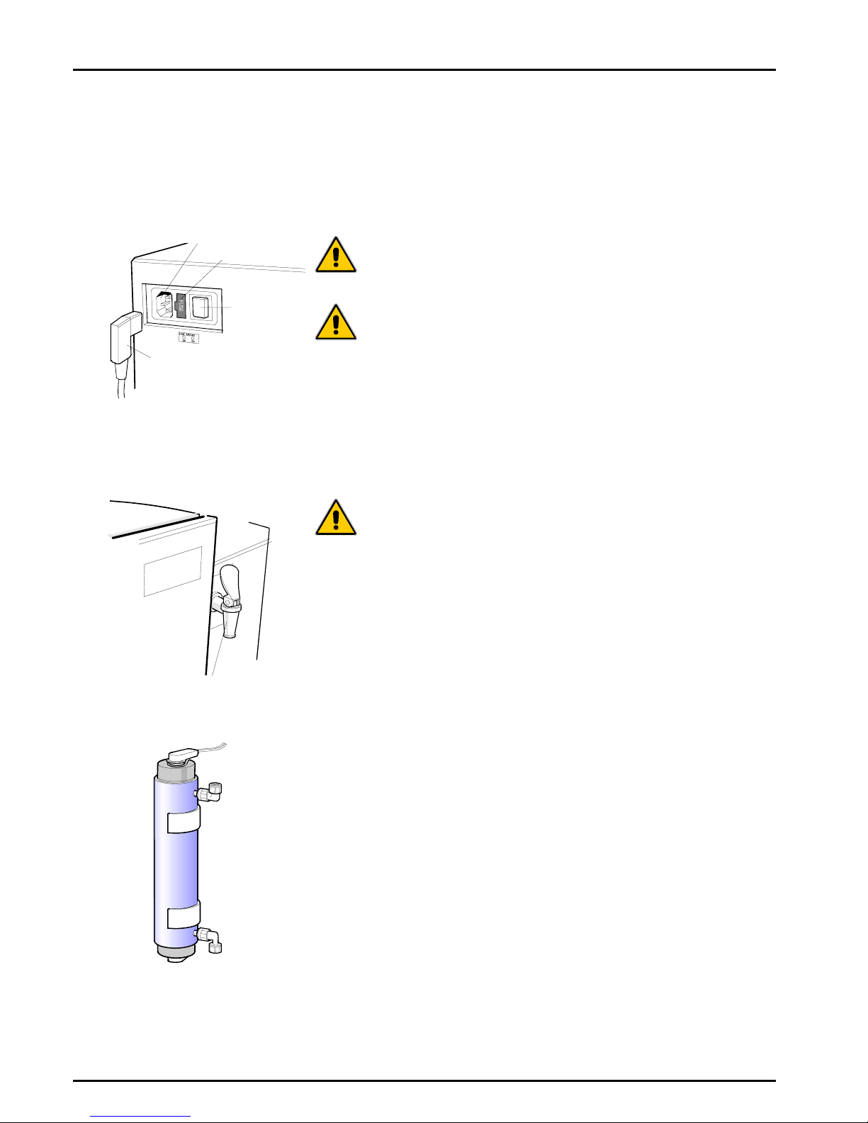
2.1 Electricity
It is essential that the electrical supply to the PURELAB Option-R is
isolated before any items are changed or maintenance work
performed.
The ON/OFF switch is located at the left-hand side of the unit. The
mains power lead is located just behind the ON /OFF switch.
WARNING! THIS APPLIANCE MUST BE EARTHED.
2.2 Pressure
The main water supply pressure should be isolated and residual
pressure released prior to removal of any cartridges or carrying out
work on the unit.
Switching off the electrical supply will isolate the source of pressure,
but pressure trapped within the unit should be released by opening
the dispense tap until water flow stops.
2.3 Ultra-Violet Light
The PURELAB Option-R unit is fitted with an ultra-violet lamp. The
UV lamp is enclosed in a stainless steel chamber ensuring the
operator will not be exposed to UV light.
2.4 Sanitization Chemicals
During the sanitization cycle a CT1 sanitization tablet is used and
relevant safety information is included in this handbook. A safety data
sheet conforming to COSHH regulations is also provided with the
tablets and should be read before the tablet is used.
2.5 Control of Substances Hazardous to Health (COSHH)
Material safety data sheets covering the various replaceable
cartridges are available upon request. Contact your local supplier or
distributor.
Fuse
ON/OFF
switch
Mains
p
ower lead
Mains
p
ower socket
Mains Power Supply
UV Lamp
Dispense tap
Dispense Tap

ELGA PURELAB Option-R 7/15 Operator Manual
PURELAB Option-R 7/15 Version 4 08/07 Page 3
3. PRODUCT AND PROCESS
DESCRIPTION
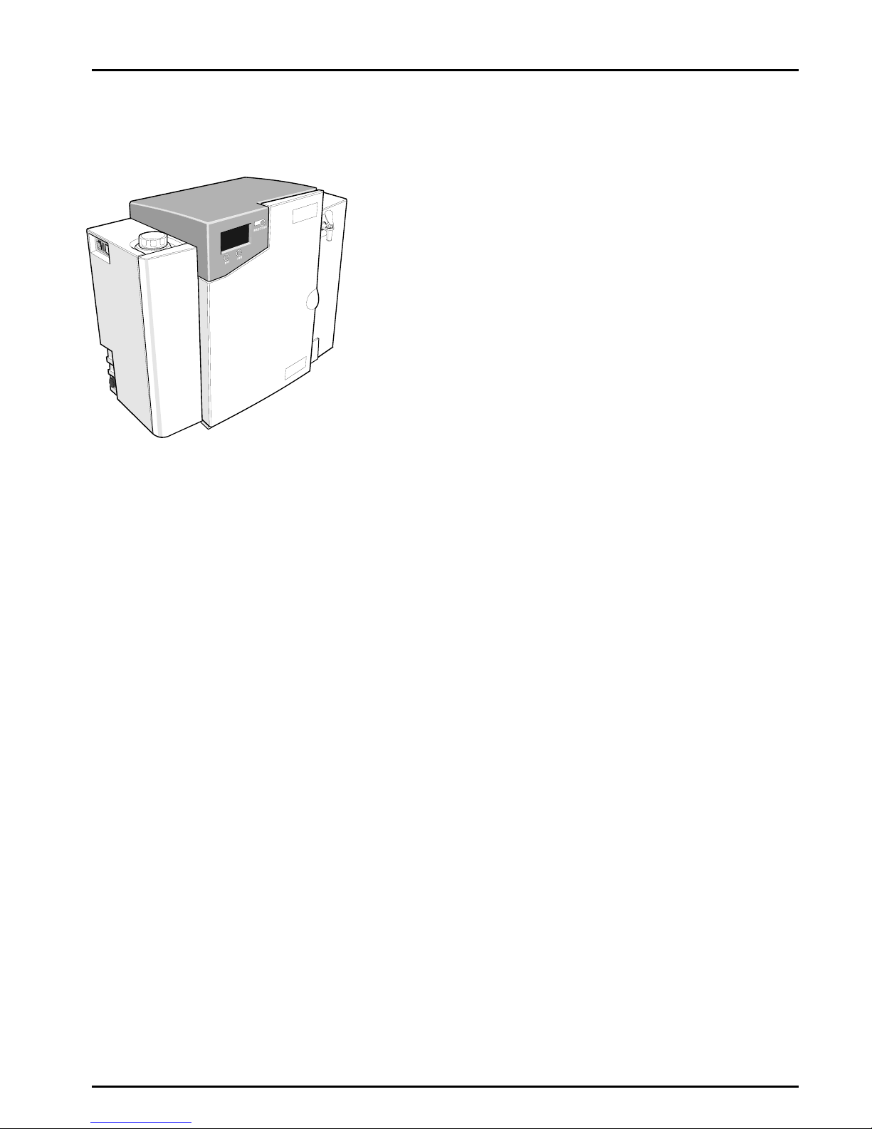
3.1 Product Description
This handbook covers the operator instructions for the PURELAB
Option-R unit.
The PURELAB Option-R water purification unit has been specifically
designed to provide a supply of highly purified water.
The PURELAB Option-R can be bench or wall mounted with an
optional wall mounting kit available. A range of accessories are
available to complement the unit. (See Section 10 - Consumables and
Accessories, for detail).
Sanitization port
Powe
r
switch ON/OFF
Mains
power
socket
Fuse
Feedwater inlet
connection
Removeable cover
Control Panel
Door
Dispense tap
A
lternative dispense
ta
p
p
osition
Removable
cove
r
PURELAB Option-R

PURELAB Option-R 7/15 Operator Manual ELGA
Page 4 PURELAB Option-R 7/15 Version 4 08/07
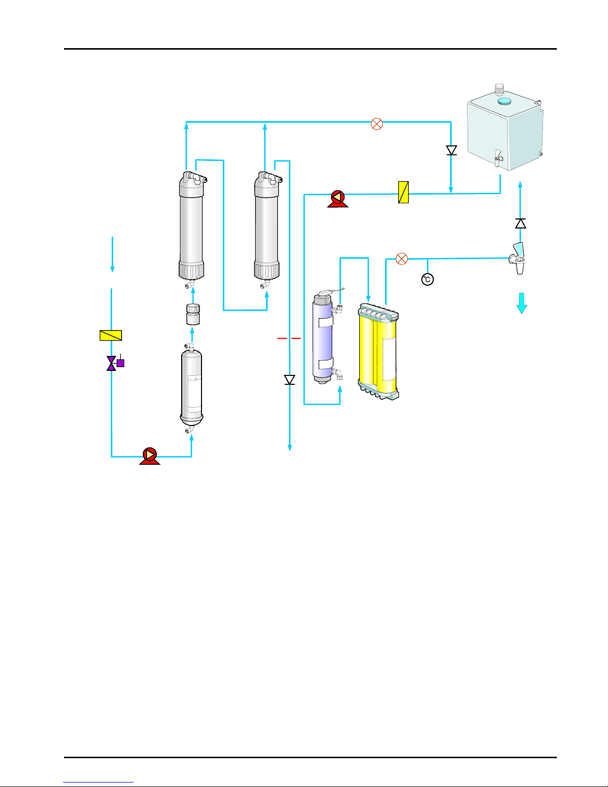
3.2 Process Description
The PURELAB Option-R process links four purification technologies,
Reverse Osmosis, adsorption, ion-exchange and photo oxidation and
also incorporates a re-circulation pump and an optional RO feed water
boost pump.
The unit is designed to operate from a good quality potable water
supply, and produces either 7 or 15 liters per hour of purified water
which is further purified and circulated through a treated water
reservoir.
A graphics screen displays the system status and provides control by
means of three function buttons.
The water is processed and treated by the PURELAB Option-R unit
as follows:
•Potable water enters through a strainer and inlet solenoid
valve at either regulated mains water pressure, or is pumped
by means of a feed water pump (optional), and passes
through the pre-treatment cartridge. The pre-treatment
cartridge has been designed to protect the reverse osmosis
cartridges from particulate/colloidal matter and excessive
free chlorine, which may be present in the incoming
feedwater.
•The permeate water then passes the sanitization port and
through one or two reverse osmosis cartridges, set up in
series, which split the flow into permeate and concentrate
streams. The permeate water is further purified whilst the
waste concentrate stream is passed to drain.
•The permeate water passes through a water quality sensor
which measures the conductivity of the water.
•The permeate water is drawn into the main re-circulation
stream by the re-circulation pump together with water from
the reservoir and passes through the re-circulation
purification loop.
•This water is pumped directly through the UV chamber
where it is exposed to intense UV radiation to provide
continuous bacterial control by photo oxidation and to
promote the cleavage of organic molecules.
•The partially purified water then passes through the ion-
exchange cartridge which removes dissolved ionic impurities
from the permeate water.
•Finally, the water is passed through a:
•Water quality sensor, which measures the resistivity of
the water.
•Temperature sensor which provides accurate
temperature measurement.
•The deionised water is either dispensed through a dispense
tap, or returns to the reservoir. An optional point of use
0.2μm bacterial filter can be fitted to the dispense tap for
added protection.
•During periods of non-use the unit will automatically operate
in intermittent re-circulation mode to maintain water purity
with maximum efficiency.
ELGA PURELAB Option-R 7/15 Operator Manual
PURELAB Option-R 7/15 Version 4 08/07 Page 5
Water quality sensor
Outlet
OutletDrain Drain
Reverse
Osmosis
LC143
Reverse
Osmosis
LC143
Inlet Inlet
Portable water
inlet
Sanitization
Port
Strainer
Solenoid
Pre-treatment
LC140
Ion-exchange
Cartridge pack
LC141
Concentrate
Drain
NRV
LC105
UV
Temp
sensor
Water quality
sensor
NRV
Pump feed
from Reservoir
NRV
Dispense tap
Purified water
outlet
Outlet
to
reservoir
Strainer
Recirculation
pump
Flow
controller
Boost pump
(optional)
Process Flow - PURELAB Option-R
Reservoir
PURELAB Option-R 7/15 Operator Manual ELGA
Page 6 PURELAB Option-R 7/15 Version 4 08/07
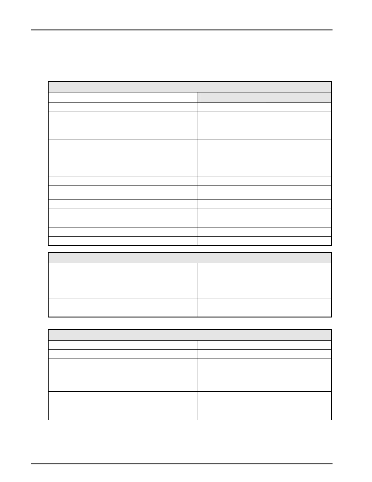
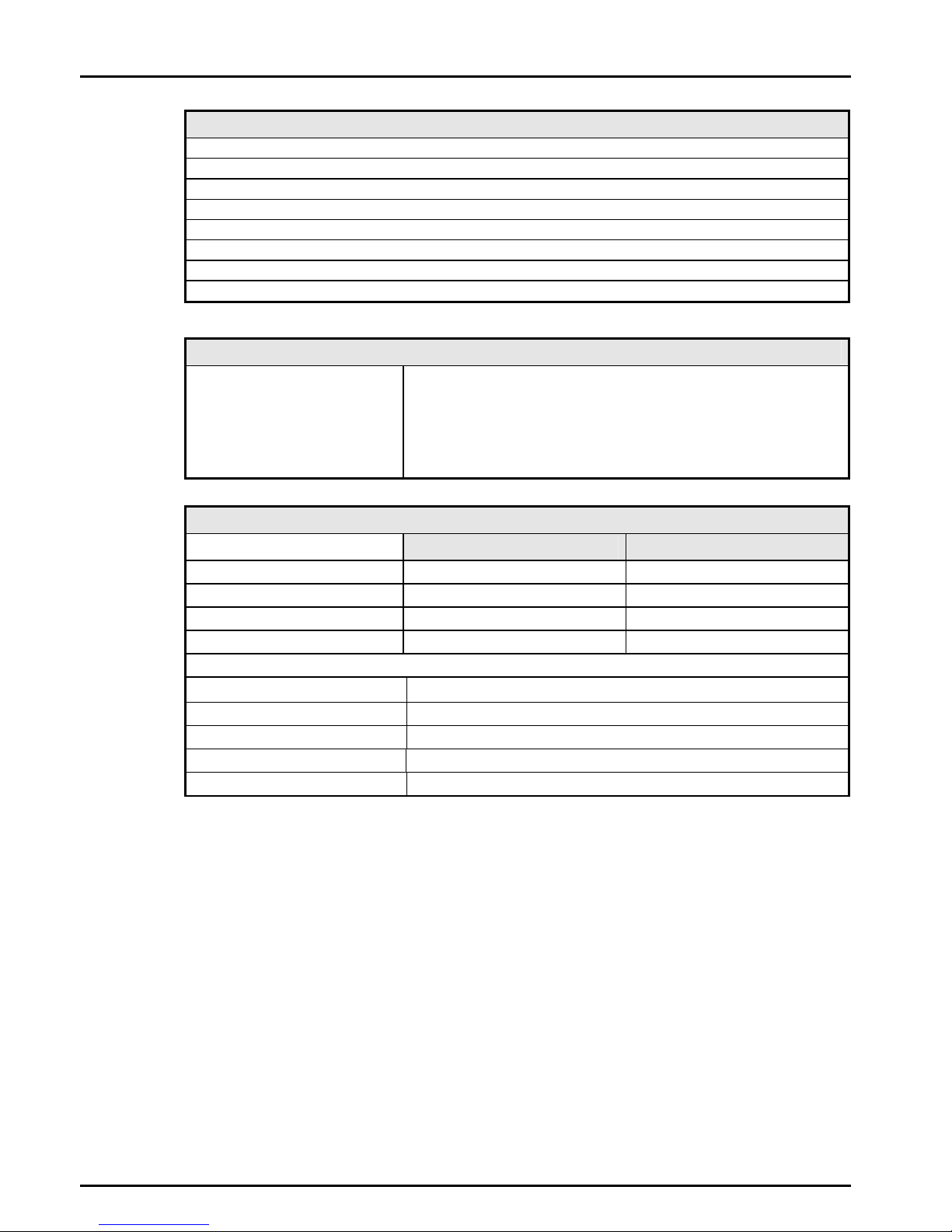
3.3 Technical Specifications
The Technical Specifications for the PURELAB Option-R are as
follows:
Feedwater
PURELAB Option-R 7 PURELAB Option-R 15
Feedwater
Source Quality Potable mains water supply Potable mains water supply
Fouling Index-maximum 10 10
Total Dissolved Solids-maximum 1400μS/cm 1400μS/cm
Free Chlorine - maximum 0.5ppm 0.5ppm
Heavy Metals - maximum 0.05ppm 0.05ppm
Silica- maximum 30ppm 30ppm
Temperature 1 - 35°C 1 - 35°C
Flowrate (Maximum requirement) 78 l/hr 85 l/hr
Drain Requirements (gravity fall with air gap). Maximum during
Service 70 l/hr 70 l/hr
Feedwater Pressure
Maximum - without internal boost pump 6.0 bar (90 psi) 6.0 bar (90 psi)
Minimum - without internal boost pump 4.0 bar (60 psi) 4.0 bar (60 psi)
Maximum - with internal boost pump 2.0 bar (30 psi) 2.0 bar (30 psi)
Minimum - with internal boost pump Flooded Suction Flooded Suction
Dimensions
Height 460mm (18.1") 460mm (18.1")
Width 550mm (21.7") 550mm (21.7")
Depth 270mm (10.6") 270mm (10.6")
Weight
With internal boost pump 20kg (44lb) 21kg (46lb)
Without internal boost pump 18kg (40lb) 19kg (42lb)
Connections
Inlet-quick connect 8mm (5/16") OD 8mm (5/16") OD
Outlet-quick connect 8mm (5/16") OD 8mm (5/16") OD
Drain RO-quick connect 8mm (5/16") OD 8mm (5/16") OD
Reservoir feed/return-quick connect 8mm (5/16") OD 8mm (5/16") OD
Positioning Wall, bench or under bench
mounted. Wall, bench or under bench
mounted.
Environment Clean dry indoor.
Temp 5 - 40°C.
Humidity max 80%
non-condensing.
Clean dry indoor.
Temp 5 - 40°C.
Humidity max 80%
non-condensing.

ELGA PURELAB Option-R 7/15 Operator Manual
PURELAB Option-R 7/15 Version 4 08/07 Page 7
Electrical Requirements
Mains Input 100-240V ac, 50-60Hz all models
System Voltage 24V dc
Power Consumption with boost pump 80VA
Power Consumption without boost pump 50VA
Fuses 2 x T6.3 Amp
Reservoir level connection Jack Plug 3.5mm
Noise Level <45dBA
User Interface
Display Continuous graphical and numerical reservoir level display
Graphical flow schematic on screen with mimic display
Intuitive icons (Multilingual)
Adjustable settings Auto restart after power failure Selectable
Audible alarm Selectable
Water purity units MicroSiemen/cm or MegaOhms.cm
Water purity Alarm setpoints
Indicators Reverse osmosis permeate water Conductivity
De-ionized water Temp compensated resistivity/ conductivity
Temperature Degrees centigrade
Reservoir % Full
Pre-treatment cartridge Maximum remaining life indicator
UV lamp Maximum remaining life indicator
Ion-exchange cartridge Maximum remaining life Indicator
Alarms-Audiovisual Purified water purity Outside set point alarm
Reservoir Low level
Reservoir Level control disconnect alarm
UV failure alarm Non start or current outside limits
Pre-treatment cartridge Change reminder
UV lamp
Ion-exchange cartridge
Change reminder
Change reminder
Outputs RS232 Printer connection
RS232 Remote display connection
Volt free contact-internal
Safety Features
Power fail safe
Boost pump protection from particulates
Re-circulation pump protection from particulates
Low operating voltage 24V
Audio visual alarms
Adjustable alarm settings
PURELAB Option-R 7/15 Operator Manual ELGA
Page 8 PURELAB Option-R 7/15 Version 4 08/07
Special Features
Low noise levels – minimum intrusion
Flow rate upgradable
Optional internal boost pump for low pressure feed waters
Optional printer kit for record of operating parameters
Optional remote display
Intermittent re-circulation “sleep” mode
Optional point of use filter
Dual position dispense tap
Technologies
Purification Methods Adsorption
Reverse Osmosis
Ultra Violet radiation-short wavelength
Ion-exchange
Point of use filtration
Purified Water Specification
PURELAB Option-R7 PURELAB Option-R15
*Make Up Rate 7.5 l/hr 15 l/hr
*Daily Output(nominal max) 180 l/24 hour day 360 l/24 hour day
Dispense Rate from Tap 1.0 l/min-nominal (less with POU filter) 1.0 l/min-nominal (less with POU filter)
Output reverse pressure (max) 0.1 bar (1psi) 0.1 bar (1psi)
Purity: (from dispense tap)
Inorganic-Typical 10 to >15MΩ.cm @25°C
Total Organic Carbon(TOC) <20ppb
**Bacteria <1CFU/ml
pH Effectively neutral
Particles Optional 0.2µm POU filter
* Standard conditions are 4 bar inlet pressure, 0 bar back
pressure at 15 degrees centigrade, fed with potable water and a
clean pre-treatment cartridge. Refer to flow tables outside these
conditions.
** Subject to correct operating and maintenance procedures.
As part of our policy of continual improvement we reserve the right to
alter the specifications given in this document.
ELGA PURELAB Option-R 7/15 Operator Manual
PURELAB Option-R 7/15 Version 4 08/07 Page 9
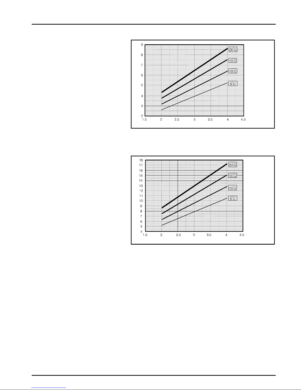
PURELAB Option-R Reverse Osmosis Capacity Charts
Option-R7
Flow (l/hr)
Pressure
(
bar
)
Graph 1 - Nominal Flowrate vs Inlet Pressure for
PURELAB Option-R7
Option-R15
Flow (l/hr)
Pressure
(
bar
)
Graph 2 - Nominal Flowrate vs Inlet Pressure for
PURELAB Option-R15
PURELAB Option-R 7/15 Operator Manual ELGA
Page 10 PURELAB Option-R 7/15 Version 4 08/07
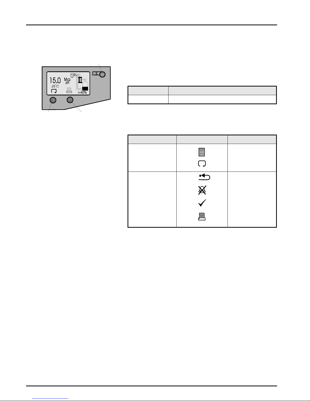
4. CONTROLS
The PURELAB Option-R operates with a tactile membrane touch pad
control panel which has a graphics display window and three program
function control buttons.
Details of how to use the controls will be given in the appropriate
sections.
Control Button Function
PROCESS Turns the process ON/OFF.
The PURELAB Option-R control panel has a range of control icons
as follows:
Button Icon Description
LEFT
Menu
Scroll
RIGHT
Reset
Mute Alarm
Accept
Printer
Process button
Right hand
control button
Left hand
control button
Control Panel

ELGA PURELAB Option-R 7/15 Operator Manual
PURELAB Option-R 7/15 Version 4 08/07 Page 11
5. INSTALLATION INSTRUCTIONS
5.1 Unpacking the PURELAB Option-R
The following items should be supplied with your PURELAB
Option-R:
1. PURELAB Option-R unit
2. Cartridge Pack LC141
3. Sanitization by-pass block fitted in the unit
4. Installation kit (LA513 or LA506)
5. Operator manual
6. Mains Lead
5.2 Positioning the PURELAB Option-R
Before commencing with installation and operation of the PURELAB
Option-R unit, please read and observe the following points.
Environment
The unit should be installed on a flat, level surface, in a clean,
dry environment. The unit can also be wall mounted against a
vertical wall capable of supporting the weight (for this we
recommend the use of the wall mounting kit Part No LA610).
CAUTION!If unit is to be wall mounted, ensure it is
mounted on a substantial brick or concrete
solid wall capable of supporting the
operating weight of the system. If
mounting the unit on the wall, use the wall
mounting kit and follow the instructions
included in the kit.
Note: Refer to specifications for unit weights.
The unit is designed to operate safely under the following conditions:
•Indoor Use
•Altitude up to 2000m
•Temperature Range 5 - 40°C
•Maximum Relative Humidity 80% @ 31°C decreasing
linearly to 50% @ 40°C, non-condensating
The unit is in Installation Category II, Pollution Degree 2, as per
IEC1010-1.
Rear mounting locations points
Unit Rear Mounting Points
PURELAB Option-R 7/15 Operator Manual ELGA
Page 12 PURELAB Option-R 7/15 Version 4 08/07
Electrical
The unit can be connected universally to any electrical supply in
the range of 100 - 240V and 50 - 60Hz. The mains lead is
supplied with a molded plug on one end and a molded
connector to the unit on the other. The unit should be
connected to an earth.
Drain
A semi rigid flexible connection to a sink or suitable drain
capable of handling at least 1.5 l/min is required. The drain
point should have a gravity fall below the level of the unit and
any connections direct to drain should have an air-break device
fitted.
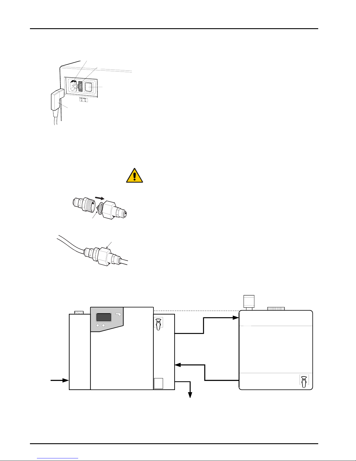
Feed Water
The feed water should be of good quality and comply with
specifications provided. This should enter the unit via an 8mm
(5/16") O/D semi rigid tube, and should be in the temperature
range 1 to 35°C.
CAUTION! Operating temperatures outside the range
1 to 35°C will cause damage to the
PURELAB Option-R unit.
For pressurized feeds, the minimum direct inlet pressure is
4.0 bar (60 psi) and maximum inlet pressure is 6 bar (90 psi).
Higher feed water pressures must be reduced using a pressure
regulator valve (Part No. LA512).
Reservoir feeds to the PURELAB Option-R unit should be
positioned at the same height, or above the unit, to provide a
positive flooded inlet pressure.
PURELAB Option-R
Level control cable
RESERVOIR
Pump
feed
Inlet
Drain
A
ll tube connections 8mm (5/16")
PURELAB Option-R Unit Installed with Storage Reservoir
Direction of
water flow
Collar
Collar
Mesh filter
Strainer
Feed Water Strainer
Mains power socket
Mains power lead
Fuse
ON/OFF
switch
Electrical Connections
ELGA PURELAB Option-R 7/15 Operator Manual
PURELAB Option-R 7/15 Version 4 08/07 Page 13
Outlet to
reservoir
Recirculation
from reservoir
Blank
Drain
Recirculation and Drain Connections
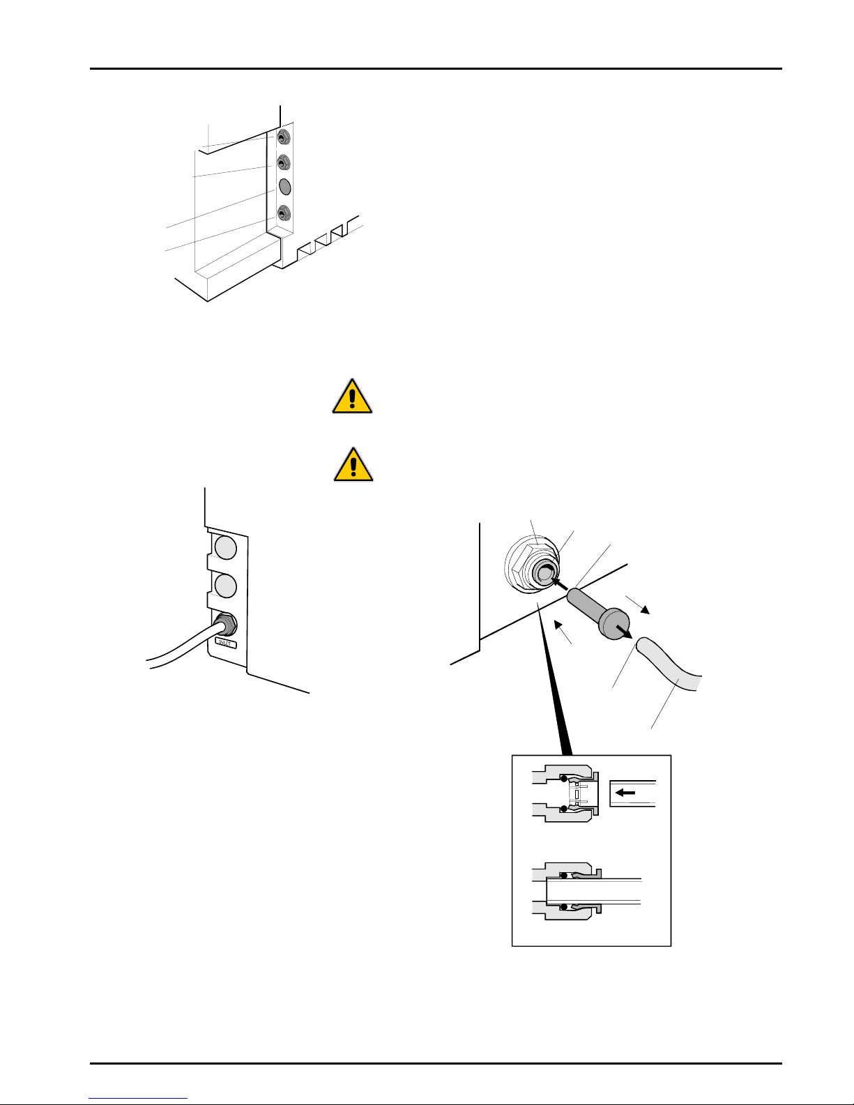
5.3 Connecting up the PURELAB Option-R
Once the PURELAB Option-R unit has been positioned either on a
wall or on a bench, it should be connected as follows:
•Mains water inlet tube
•Drain
•Re-circulation from reservoir
•Outlet to reservoir
Step 1 - Fitting Tubes
1. PUSH in collet on connector.
2. PULL out transit plug.
3. CUT a clean square end on a 8mm (5/16") OD
semi rigid drain tube.
4. PUSH tube into connector.
CAUTION! Do not restrict drain line.
CAUTION! If the water supply is at a pressure greater
than 6 bar (90 psi) fit a pressure regulator
(LA512).
Connecto
r
Collet Blanking
transit plug
Pull plug
Depress
collet
Clean square
cut end
Tube 8mm OD
Simply push in tube to attach
Tube in secured position
Fitting Tubes
Feedwater Inlet Connections

PURELAB Option-R 7/15 Operator Manual ELGA
Page 14 PURELAB Option-R 7/15 Version 4 08/07
Step 2 - Connect Electrical Supply
1. PLUG mains lead into the socket on the left hand
side of the PURELAB Option-R unit.
2. PLUG mains lead into mains socket.
Step 3 - Connect High/Low Level Switch to Reservoir
1. INSERT jack plug into the level control socket
located at rear of unit and reservoir.
Level control
Reservoir Level Connections
Mains power socket
Fuse
ON/OFF
switch
Mains power lead
Electrical Connections

ELGA PURELAB Option-R 7/15 Operator Manual
PURELAB Option-R 7/15 Version 4 08/07 Page 15
Step 4 - Positioning Dispense Tap
The Dispense Tap may be fitted at a high level or a low level on
the PURELAB Option-R unit, to allow for easier access when
wall mounted.
To alter the location of the Dispense Tap:
1. Switch the PURELAB Option-R off at the power
switch at the top left hand side of the unit.
2. Ensure the water supply is turned off.
3. Dissipate pressure by opening the dispense tap.
4. Open the front door.
5. Remove the LC141 cartridge. (See section 7.2).
6. Unscrew the two panel fixing screws located on
the right hand side of the door opening.
7. Remove side panel by sliding the panel to the
rear. Once unhooked, remove.
8. Remove screws holding dispense tap manifold.
9. Locate manifold in alternative position.
10. Replace panel.
11. Replace LC141 cartridge. (See section 7.2).
12. Switch electrical power on.
13. Switch water supply on.
14. Press the process button.
15. Ensure correct operation of dispense tap.
Panel
fixing
screws
Slide back,
unhook and
remove side
panel
Manifold
screws
Replacing side panel
Panel
fixing
screws
Manifold
screws
Replace
side panel
Positioning the Dispense Tap
This manual suits for next models
2
Table of contents
Popular Water Dispenser manuals by other brands


Midea
Midea MYD10S-W manual

Elkay
Elkay VRCTL Series Installation, care & use manual

Whirlpool
Whirlpool 8171413 installation instructions

Omnifilter
Omnifilter R800 installation instructions

Hague Quality Water
Hague Quality Water WaterMax ST Series Owner's manual and installation guide

Aquverse
Aquverse B11A Troubleshooting instructions supplement