Elgama DC12U User manual

DC12U G3 v1.3
PLC Data concentrator
DC12U
G3 PLC
User Manual
Version 1.3
“ELGAMA – ELEKTRONIKA” Ltd., Lithuania 2020

DC12 PLC Data Concentrator User Manual
Please consider the environment before printing this document. 1
This Page is blank intentionally.

DC12 PLC Data Concentrator User Manual
Please consider the environment before printing this document. 2
Copyright Notice
This publication, including all photographs, illustrations and software, is protected under international
copyright laws, with all rights reserved. Neither this manual, nor any of the material contained herein,
may be reproduced without written consent of the author.
Disclaimer
The information in this document is subject to change without notice. The manufacturer makes no
representations or warranties with respect to the contents hereof and specifically disclaim any implied
warranties of merchantability or fitness for any particular purpose. The manufacturer reserves the right
to revise this publication and to make changes from time to time in the content hereof without obligation
of the manufacturer to notify any person of such revision or changes.
Limitations of Liability
UNDER NO CIRCUMSTANCES SHALL ELGAMA-ELEKTRONIKA OR ITS SUPPLIERS BE LIABLE FOR DAMAGES
OF ANY CHARACTER (E.G. DAMAGES FOR LOSS OF PROFIT, SOFTWARE RESTORATION, WORK STOPPAGE,
LOSS OF SAVED DATA OR ANY OTHER COMMERCIAL DAMAGES OR LOSSES) RESULTING FROM THE
APPLICATION OR IMPROPER USE OF THE ELGAMA-ELEKTRONIKA PRODUCT OR FAILURE OF THE PRODUCT,
EVEN IF ELGAMA-ELEKTRONIKA IS INFORMED OF THE POSSIBILITY OF SUCH DAMAGES. FURTHERMORE,
ELGAMA-ELEKTRONIKA WILL NOT BE LIABLE FOR THIRD PARTY CLAIMS AGAINST CUSTOMER FOR LOSSES
OR DAMAGES. ELGAMA-ELEKTRONIKA IN NO EVENT WILL BE LIABLE FOR ANY DAMAGES IN EXCESS OF
THE AMOUNT ELGAMA-ELEKTRONIKA RECEIVED FROM THE END-USER FOR THE PRODUCT.
© 2020 “Elgama-Elektronika”, Ltd. All rights reserved

DC12 PLC Data Concentrator User Manual
Please consider the environment before printing this document. 3
Table of Contents
1 Introduction ..........................................................................................................................................5
1.1 Audience .......................................................................................................................................5
1.2 Other Documentation...................................................................................................................5
1.3 Conventions ..................................................................................................................................5
1.4 Notes, Notices and Cautions.........................................................................................................6
2 Safety ....................................................................................................................................................7
2.1 Safety requirements .....................................................................................................................7
2.2 Transportation and storage rules .................................................................................................7
2.3 Prevention and elimination of malfunctions ................................................................................7
2.4 Proper disposal of product ...........................................................................................................8
3 Technical specifications ........................................................................................................................9
3.1 Concentrator and modem status indication...............................................................................10
4 DCU Configuration using Web UI........................................................................................................12
Supported Browsers............................................................................................................................12
WEB UI user levels ..............................................................................................................................12
WEB UI supported functions...............................................................................................................12
4.1 Usage...........................................................................................................................................12
4.1.1 Access DC12U WEB UI.........................................................................................................12
4.2 DCU running status information.................................................................................................13
4.2.1 Basic Information................................................................................................................13
4.2.2 DC12U collected data monitoring.......................................................................................14
4.2.3 Meters –Generate CSV.......................................................................................................16
4.2.4 Meters tree .........................................................................................................................16
4.2.5 Status. System.....................................................................................................................18
4.2.6 Meters Activity....................................................................................................................21
4.2.7 Status. Runtime information...............................................................................................22
4.3 DCU configuration.......................................................................................................................22
4.3.1 System settings ...................................................................................................................22
4.3.2 Settings. WEB......................................................................................................................25
4.3.3 Firmware update.................................................................................................................27
5 DCU Configuration using DC Configurator..........................................................................................29
5.1.1 Supported Operating systems ............................................................................................29
5.1.2 DC configurator supported functions .................................................................................29

DC12 PLC Data Concentrator User Manual
Please consider the environment before printing this document. 4
5.1.3 Application interface...........................................................................................................29
5.1.4 Upgrading DC Configurator application..............................................................................30
5.2 Adding DCU to managed devices................................................................................................30
5.3 DCU parameters..........................................................................................................................31
5.3.1 Configuration tab................................................................................................................31
5.3.2 DCU Options tab .................................................................................................................31
5.3.3 DCU Settings tab .................................................................................................................33
5.3.4 FW Update tab....................................................................................................................36
5.3.5 Meter tariff modification tab..............................................................................................37
5.3.6 Meter parameter update tab..............................................................................................40
5.4 Meter parameters.......................................................................................................................40
5.5 Controller data inspector............................................................................................................43
6 DCU SMS management.......................................................................................................................47
6.1 SMS management configuration in WEB UI ...............................................................................47
6.2 SMS Commands from phone......................................................................................................47
6.2.1 SMS command examples....................................................................................................48
Appendix A. Data gathered by DC12U from meters...................................................................................49
Appendix B. GSM LED description ..............................................................................................................50
Appendix C. DC12U Dimensions and installation. ......................................................................................51

DC12 PLC Data Concentrator User Manual
Please consider the environment before printing this document. 5
1Introduction
This manual’s feature descriptions are based on the software release 1.2. The features listed here are
the subset of features that are supported by the DC12U PLC data concentrator.
1.1 Audience
This reference manual is intended for administrators and other engineers responsible for installing and
managing the DCU by using the DC configurator or Web User Interface (Web UI). The Web UI is the primary
management interface to the Data Concentrator Unit, which will be generally referred to simply as the
“DCU” within this manual. This manual is written in a way that assumes that you already have the
experience and knowledge of Ethernet, modern networking and energy measurement principles.
1.2 Other Documentation
The documents below are a further source of information in regards to configuring and troubleshooting
the DCU. All the documents are available from Elgama-Elektronika website (www.elgama.eu). Other
documents related to this DCU are:
• DC12U Hardware Installation Guide
• DC12U Brief Reference Guide
1.3 Conventions
Convention
Description
Boldface Font
Indicates a button, a toolbar icon, menu, or menu item. For
example: Open the File menu and choose Cancel. Used for
emphasis. May also indicate system messages or prompts appearing
on screen. For example: You have mail. Bold font is also used to
represent filenames, program names and commands. For example:
use the copy command.
Initial capital letter
Indicates a window name. Names of keys on the keyboard have
initial capitals. For example: Click Enter.
Menu Name > Menu Option
Indicates the menu structure. Device > GSM > GSM Properties
means the GSM Properties menu option under the GSM menu
option that is located under the Device menu.
Blue Courier Font
This convention is used to represent an example of a screen console
display including example entries of CLI command input with the
corresponding output.

DC12 PLC Data Concentrator User Manual
Please consider the environment before printing this document. 6
1.4 Notes, Notices and Cautions
Below are examples of the three types of indicators used in this manual. When administering your DCU
using the information in this document, you should pay special attention to these indicators. Each
example below provides an explanatory remark regarding each type of indicator.
NOTE: A note indicates important information that helps you make better use of your
device.
NOTICE: A notice indicates either potential damage to hardware or loss of data and tells you
how to avoid the problem.
CAUTION: A caution indicates a potential for property damage, personal injury, or death.

DC12 PLC Data Concentrator User Manual
Please consider the environment before printing this document. 7
2Safety
2.1 Safety requirements
Installing, uninstalling, parameterization and verification can be performed only by authorized
organizations that have qualified technicians. Only qualified persons should install DCU.
DCU connection or disconnection from network should be done when voltage in the network is turned
off. A protection from accidental network voltage connection must be established.
No accessories can be hanged on a DCU, it is forbidden to hit or strike DCU case.
Precautions must be taken in battery changing procedure:
A. DCU has to be disconnected from electricity network, a protection from accidental network
voltage connection must be assured;
B. Use pincers or similar instruments to change battery (connection/disconnection of a plug).
2.2 Transportation and storage rules
Prior to the usage DCU must be kept in a closed room in a transportation packing, where the temperature
ranges from 5°C to 40°C and average area humidity is up to 80% when temperature being 25°C. The room
must be without harmful gas or steam. DCU must be kept and exploited in premises protected from dust,
aggressive vapors and gasses.
Unpacked DCU can be kept only in repair workshop. The temperature must range from 10°C to 35°C,
average area humidity must not exceed 80% when temperature being 25°C.
During wintertime DCU must be kept in a heated room for 6 hours or more, before they are used.
DCU must be transported only in closed vehicles (carriage, container, hold). Shake acceleration can not
exceed 30m/s², 80-120 strikes per minute. The temperature must be within -40°C to +70°C range,
average area humidity must not exceed 98% when temperature being 35°C.
2.3 Prevention and elimination of malfunctions
If suspected that DCU works improperly, the following actions should be performed:
Exterior inspection. Before applying voltage to the DCU, make sure its case has no mechanical damages,
there are no signs of overheating, and all wires are properly connected.
Do not plug a concentrator into power network if it is mechanically damaged. This can cause staff
injuries and destroy DCU as well as other equipment!
Inspection of connection and parameterization constants. Installing, uninstalling, parameterization and
verification can be performed only by authorized organizations that have qualified technicians. After
plugging a DCU into electric network technician should check whether date and time are correct, set
concentrator IP and gateway addresses according user network requirements.
DC12 PLC Data Concentrator User Manual
Please consider the environment before printing this document. 8
Procedure of returning DCU to manufacturer. In case malfunctions cannot be eliminated on the spot, the
DCU should be returned to the manufacturer for repair or replacement. DCU upon return to manufacturer
must have Passport with notices of organization in charge of their exploitation and short description of
DCU malfunctioning.
2.4 Proper disposal of product
This sign indicates, that this product cannot be thrown out with any other
waste when its validity period is over if this sign is on the product or it is
included in product’s description. In order to prohibit possible harm for
environment and human health because of uncontrolled waste
elimination, please separate this product from other forms of waste, and
if it is possible use this product or its parts repeatedly in recycling
process. Home users can contact product manufacturer or local
administration for information about product utilization and recycling
without any harm to the environment. Enterprises must contact their
own providers to revise product’s validity terms and conditions stated in
purchase agreements. This product cannot be thrown out with any other
waste of different kind.

DC12 PLC Data Concentrator User Manual
Please consider the environment before printing this document. 9
3Technical specifications
Technical specifications are subject to change without prior notice.
PLC Data concentrator DC12 conforms to the following requirements of directives and standards:
•Directive 2004/108/EC of the European Parliament and of the Council of 15 December 2004 on
the approximation of the laws of the Member States relating to electromagnetic compatibility and
repealing Directive 89/336/EEC;
•IEC 529 “Degrees of protection provided by enclosures”;
•IEC 61334-4-41 “Distribution automation using distribution line carrier systems – Part 4: Data
communication protocols –Distribution line message specification”;
•IEC 62056-46 Data link layer using HDLC protocol;
•IEC 62056-53 DLMS/COSEM Application Layer;
•IEC 62056-61 DLMS/COSEM Obis code;
•IEC 62056-62 DLMS/COSEM Interface Classes;
•EN 50065-1 Signaling on low-voltage electrical installations in the frequency range 3 kHz to 148,5
kHz –Part 1: General requirements, frequency bands and electromagnetic disturbances.
Operating voltage Un, V:
220/380 +/- 20% 3x230/400 V
Operating voltage range, % from Un:
-20... +20
Reference frequency, Hz:
50
Power consumption standby:
< 7W
Power consumption MAX:
<10 W
Internal clock error
< 0,5 s/24 h (T=23°C)
Backup power supply for clock
Super CAPs and Li-ion battery
Operation duration using only backup power supply
10 years
Communication interfaces:
Ethernet
Two 10/100BASE-T ports
PLC
EN 50065-1 CENELEC A-band (3 –95 kHz)
PLC communication:
G3 PLC (IEEE P1901.2, ITU G.9903)
2G/3G/4G modem:
LTE FDD: B1/B3/B7/B8B20/B28A
WCDMA: B1/B8
GSM: 900/1800 MHz
Isolation:
Pulse voltage tests (IEC 60060-1)
6 kV @ 1,2/50µs
Protection against dust and water
IP51
Insulation
Protective class II
Temperature range, Operation:
- 40 … +70°C
Temperature range, Storage, transportation:
- 40 … +70°C
Mass, kg:
< 3
Dimensions (HxWxD), mm
290 x 180 x 95
Average service life (years)
16
DC12U has 512 MB RAM and 4096 MB Flash. DC12U is designed to support up to 500 meters.

DC12 PLC Data Concentrator User Manual
Please consider the environment before printing this document. 10
DC12U uses two-way communication in both PLC and cellular networks for metering data reading and
meter/PLC data device management.
PLC modem fully integrated inside DC12U data concentrator. Modem is based on ST8500 solution and is
operating using G3 PLC technology. DC12U PLC modem supports FCC (150-490kHz) or CENELEC-A (35-
91kHz) frequency bands. Electromagnetic emissions of the modem does not exceed standardized values
according EN55022 when operating at above two frequency bands.
DC12U PLC modem ensures PLC MAC security according G3 PLC technology by using 128 bit length pre-
shared key (PSK). DC12U will be configured with purchaser provided PSK.
DC12U data concentrator supports remote and local configuration possibility for G3 PLC modem, change
modem parameters, change used frequency band. Data concentrator G3 PLC modem uses all three
phases for PLC communication with meters.
GSM 2G/3G/4G modem is based on CE certified Quectel EG91-E LTE module. For data transfer modem
uses IPv4 protocol. Modem is DCU module installed in DCU compartment for communication modules.
Modem SIM card is protected with cover on modem housing top. Modem cover construction enables
open it by hand and SIM card is accessible without any instrument. Communication modules
compartment cover may be sealed, so modem is protected from unauthorized access. Modem has
antenna with electrically isolated body. Antenna connected to modem using SMA type connector.
After power on, data concentrator automatically registers all available electricity meters. In normal
conditions, data concentrator periodically checks meters accessibility on PLC network and checks for new
meters events. All mentioned operations periodicity configured by user locally or remotely. If new meters
events are available, DC12U reads them from meter and stores in local database for transfer to HES.
DC12U configuration (parametrization) and FW update can be complete locally by using WEB GUI or
remotely by using HES. For local DCU management WEB GUI is used. WEB GUI is accessible over any
Ethernet port or through mobile connection.
3.1 Concentrator and modem status indication.
Main indicators: power ON LED indication, named “RUN” is system heartbeat. It blinks when system is
running. Alarm indication, named “ALARM” flashes when DCU is in alarm state. Possible alarm reasons:
•Tamper –DC12U terminal cover was removed. Trigger is not active up to 4 hours from first DCU
power on, for alarm free installation of DCU.
•Invalid configuration –error in settings file.
•User triggered.
•GSM modem missing.
•SIM missing.
•Service failure –one of internal services has failed.
•Phase disconnected –one or more feeding phases disconnected.
•Low internal storage –less than 100MB of free FLASH available.
PLC Module indicators (RED):
•Run –LED blinks when PLC module is operational;
•T/R –LED blinks when data is transmitted over PLC;
•A, B, C –Power supply phase indicators. Lit when power is present.

DC12 PLC Data Concentrator User Manual
Please consider the environment before printing this document. 11
GSM module indicators (see Appendix B. GSM LED description for details):
•LED1 [Power] –RED. Connected directly to power supply
•LED2 [Network] –RGB GSM network connection LED.
•LED3 [Activity] –RG GSM network activity LED.

DC12 PLC Data Concentrator User Manual
Please consider the environment before printing this document. 12
4DCU Configuration using Web UI
Supported Browsers
DC12U WEB UI supports following browsers: Firefox, Microsoft Edge and Google Chrome.
DCU comes with self-signed HTTPS certificate. You will receive warning from your browser about
untrusted certificate until you upload your HTTPS certificate to DCU.
WEB UI user levels
DC12G WEB UI supports two user levels
•Admin –all settings are read/write
•Guest –all settings are read only
Be aware that initial admin user can not be deleted. Initial administrator username and password is
created in factory with customer specific values. We recommend creating new user with admin
privileges for everyday activities.
WEB UI supported functions
1. DCU management;
2. Meter data overview and export;
3. GPRS module parameter management;
4. Firmware update.
4.1 Usage
4.1.1 Access DC12U WEB UI
Set your computer address to be in 10.0.2.0/24 network. Use any address in 10.0.2.3-10.0.2.254 range
and Subnet Mask should be 255.255.255.0. Please consult your operating system manual on setting static
IP address.
1. Open browser window, input DC12U network address according to connected interface.
a. Port ETH0 default IP address is 10.0.2.1 with subnet mask 255.255.255.0
b. Port ETH1 default IP address is 10.0.2.2 with subnet mask 255.255.255.0
2. Select user interface language and enter username and password.
3. Then, press SUBMIT, and wait until DC12U main menu is loaded.
Default login is admin and password admin. Please remember to change default password.

DC12 PLC Data Concentrator User Manual
Please consider the environment before printing this document. 13
Figure 4.1 Ethernet port locations on Ethernet module
4.2 DCU running status information
4.2.1 Basic Information.
WEB UI is divided into two main parts. Language selector and main menu tree is displayed on the left
side. Main window on the right side. By default Home page is displayed.
Figure 4.2. WEB UI home window
Following information available in Home main window:
Port ETH1
Port ETH0

DC12 PLC Data Concentrator User Manual
Please consider the environment before printing this document. 14
•DCU Description –admin users can change it to reflect DC12U location or other useful
information. Maximum length is 50 symbols.
•Alerts –Current active DCU alerts. Clicking on Alerts icon expands active alerts list.
•Connected users –list of currently connected to DC12U users. Access level and user IP address.
•Latest log entries –list of latest important log entries.
•Restart –DCU restart menu. It is possible to restart immediately or configure a scheduled restart.
•Meters in database –amount of meters present in DC12U database.
•PLC Data gather period –DCU collects missing data from all meters at given intervals.
•CPU usage –current CPU load.
•Disk Read/Write –current FLASH read write in kilobytes.
•Network Received/Sent –current network data in bytes.
•GSM connection –green if data connection is established, red if no data connection.
4.2.2 DC12U collected data monitoring
Information about data collected from meters available under left menu Meters.
Figure 4.3. Meter list window
DC12 PLC Data Concentrator User Manual
Please consider the environment before printing this document. 15
First submenu –List. Contains list of meters currently present in DC12U database. DCU itself is also
present in this list. No electricity meter is present in the current DC12U modification.
Amount of listed meters per page can be changed to 7, 10, 20, 25 rows. User can search meter list using
any part of meter serial number. List is sortable by any column, just click on column name. The arrow in
the column name indicates the direction of sorting. If there are no arrow, the column is ordered by the
order they appear in the database.
•Meter Name –full meter logical device name as present in DC12U database.
•Serial number –meter serial number. DC12U serial number can be modified via DC configurator
software.
•Meter type –meter type and modification.
•Firmware –meter firmware version at the moment of registration to DC12U.
•Update date –date when meter was added to DC12U database.
•Status –blacklist status: if active, data will be collected from meter. If disabled, meter connection
is maintained, but no data will be collected from that meter.
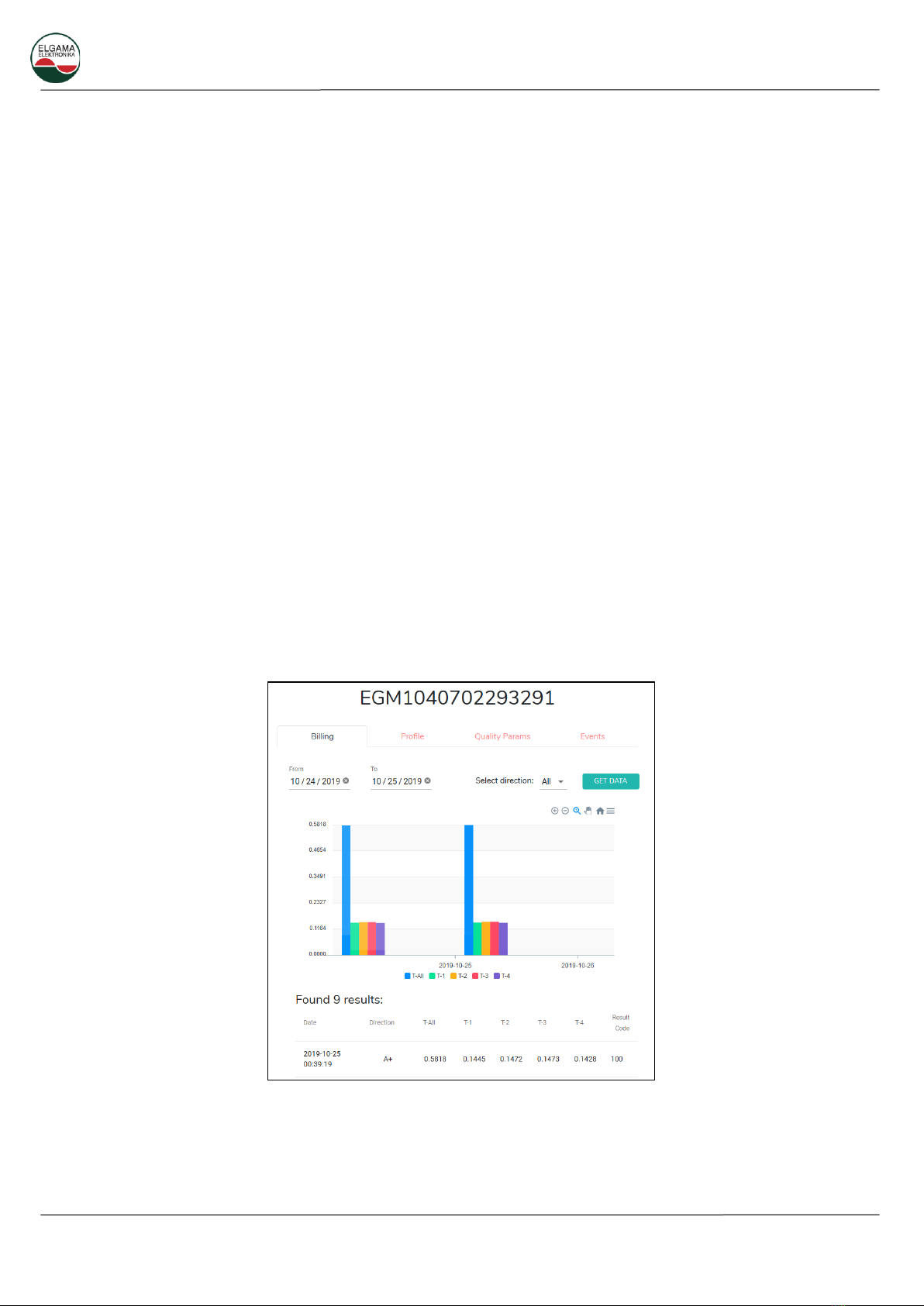
Selecting meter name, detailed data for selected period can be displayed. Available data may vary
according to specific operator SLA. All graphs can be downloaded as SVG or PNG images. Currently
available information:
Billing –Selectable period, directions: All, A+, A-, R+, R-.
Profile (Load profile) - Selectable period, directions: All, A+, A-, R+, R-.
Quality parameters - Selectable period.
Events –Events for selectable period.
Figure 4.4. Detailed data collected from meter
DC12 PLC Data Concentrator User Manual
Please consider the environment before printing this document. 16
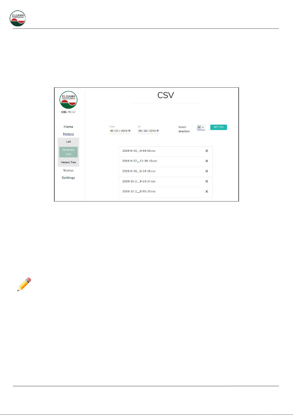
4.2.3 Meters –Generate CSV
It is possible to generate billing profile report for selected dates. CSV report includes all meters available
in specific DC12U. Data concentrator stores generated reports for repeated downloads. Maximum
number of stored reports –15. When limit is reached, oldest stored report will be deleted from DC12U.
Administrator can manually delete reports one by one.
Figure 4.5. CSV report generation window
4.2.4 Meters tree
DC12U displays PLC tree, according to meter connection path. DCU is in the center, meters accessible
directly displayed in blue. Next hop meters displayed in red. Connectors between meters have direction
arrows indicating communication direction. Whole tree representation is zoom able with mouse wheel.
Each individual meter also can be moved for better view. It is possible to search for specific meter via any
part of serial number. To the right of search field is a control where additional options can be set.
Please be warned –generating meter tree for large amount of meters can take up to 10 seconds.
•Simple layout (default) –DCU in center, direct attached meters spread evenly around DCU. All
connectors between meters displayed according to PLC signal SNR: lower SNR –longer connector.
•Hierarchical layout –all meters placed in rows.
•Show all (default ON) –if setting is disabled, meters connected directly to DCU will be hidden.

DC12 PLC Data Concentrator User Manual
Please consider the environment before printing this document. 17
Figure 4.6. Meters tree. Hierarchical layout
When hovering over each meter, detailed information related to PLC connection, is displayed.
Figure 4.7. Detailed PLC connection information for selected meter
Detailed description of PLC connection information:
•Destination Address –address of PLC node (meter) in current PLC segment. Assigned by DCU
upon meter registering to PLC network;
•Extended Address –EUI64 meter address;
DC12 PLC Data Concentrator User Manual
Please consider the environment before printing this document. 18
•Route Cost –Value calculated by LOADng protocol from number of hops, LQI (Link Quality
Indicator), ROBO mode, number of active subcarriers.
•Valid –Route information expires after some time. It is refreshed after each communication from
meter;
•Tone Map –best set of sub carriers to reach this meter;
•Modulation Type –modulation used for communication with meter. ROBO, DBPSK, DQPSK;
•Link Quality Indicator –value (0-255) measured when receiving signal from meter;
•Signal Average Noise –noise level measured in received signal;
•Signal Average Strength –level of received signal;
•Signal / Noise –calculated as SignalStrength - SignalNoise;
•Signal Total Strength –absolute value of received signal.
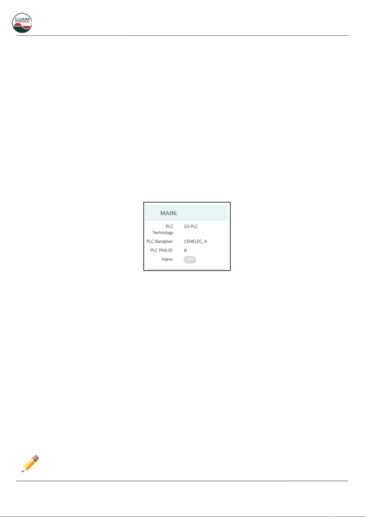
4.2.5 Status. System
Current DC12U status displayed in convenient dashboard. Statuses are grouped according to modules.
Figure 4.8. Main status information
Main. PLC information and alarm status.
•DCU PLC technology –current standard in use: G3 or PRIME.
•PLC Band plan –CENELEC_A or FCC.
•PLC PAN ID –current PAN ID used by DCU.
Alarm also is displayed by alarm LED on DC12U faceplate. If hardware platform is equipped with buzzer,
it will sound when alarm is triggered. Alarm can be triggered by following events:
•Tamper –DC12U terminal cover was removed.
•Invalid configuration –error in settings file.
•User triggered.
•GSM modem missing.
•SIM missing –SIM card is missing or damaged. If there is no SIM card, the modem periodically
reboots.
•Service failure –one of internal services has failed.
•Phase disconnected –one or more feeding phases disconnected.
•Low internal storage –less than 100MB of free FLASH available.
DC12 PLC Data Concentrator User Manual
Please consider the environment before printing this document. 19
The event alarms, except the tamper alarm, disappear if the source of the event disappear. Tamper
alarm can be shut down from “Status” page or by pressing and holding Enter (first from the right) key
on keypad for 5 seconds.
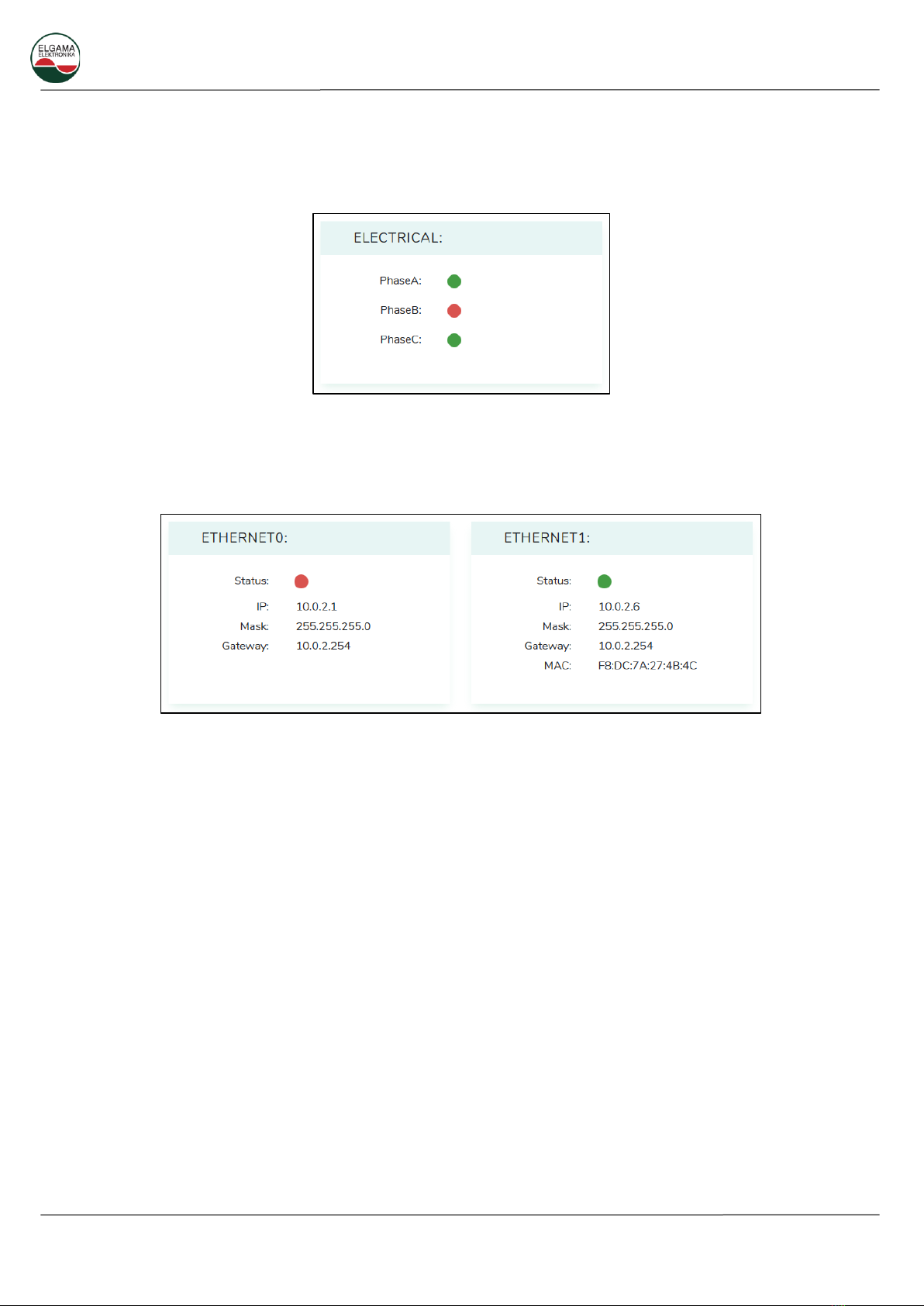
Figure 4.9. Electrical status
Electrical. Phases currently present on DC12U feed. Data is refreshed every 5 seconds.
Figure 4.10. Ethernet ports status
Ethernet. Information about Ethernet ports.
•Status –green circle means active Ethernet link.
•IP –IP address assigned to specific Ethernet interface.
•Mask –Subnet mask assigned to specific Ethernet interface.
•Gateway –gateway address assigned to specific Ethernet interface.
•MAC –Hardware address of Ethernet port. Assigned at factory.
Table of contents
Other Elgama Measuring Instrument manuals


Popular Measuring Instrument manuals by other brands

GREISINGER
GREISINGER GMH 3630 operating manual

Fluke
Fluke 845AR instruction manual

Bosch
Bosch GLM 20 Original instructions

Network Technologies Incorporated
Network Technologies Incorporated ENVIROMUX-2D Quick installation guide

Sper scientific
Sper scientific AquaShock 850046K user manual

Fluke
Fluke 374 user manual


