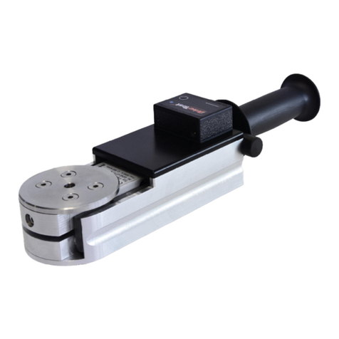
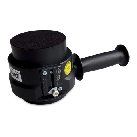
DriveTest FM300BT User manual

FM300BT
MANUAL


Pinch Force Meter FM300BT
Version 1.5 Seite 3/23
English version
Contents
1General .......................................................................................................... 5
1.1 Scope of Application.............................................................................................. 5
1.2 Product Description................................................................................................ 5
1.3 Construction.............................................................................................................. 7
1.4 Optional Modules ................................................................................................... 8
1.4.1 Spacers ................................................................................................................... 8
1.4.2 Software ................................................................................................................. 9
1.5 Technical Specifications......................................................................................10
2Safety Instructions..................................................................................... 11
2.1 Target Group...........................................................................................................11
2.2 Transportation ........................................................................................................11
2.3 Operation .................................................................................................................12
2.3.1 Battery...................................................................................................................12
2.3.2 Risks.......................................................................................................................12
2.4 Storing .......................................................................................................................13
3Preliminary.................................................................................................. 13
3.1 Battery........................................................................................................................13
3.2 Assembly of Spacers ............................................................................................13
4Operation .................................................................................................... 13
4.1 Function Overview Android App.....................................................................14
4.2 Turning On...............................................................................................................15
4.3 Connecting...............................................................................................................15
4.3.1 Bluetooth connection .....................................................................................15
4.3.2 USB connection.................................................................................................16
4.4 Measuring ................................................................................................................16
4.4.1 Device positioning ...........................................................................................17
4.4.2 Mounting spacers ............................................................................................18
4.4.3 Start measuring.................................................................................................18
4.5 Turning Off...............................................................................................................19
4.6 Charging ...................................................................................................................19
4.7 Errors ..........................................................................................................................20

Pinch Force Meter FM300BT
Version 1.5 Seite 4/23
5Service ......................................................................................................... 21
5.1 Calibration................................................................................................................21
5.2 Maintenance............................................................................................................21
5.3 Warranty ...................................................................................................................21
5.4 Contact ......................................................................................................................22
6Shutdown.................................................................................................... 22
6.1 Disposal.....................................................................................................................22
7Appendix..................................................................................................... 23
7.1 EC certificate of conformity...............................................................................23
7.2 Glossary.....................................................................................................................24
7.3 List of figures...........................................................................................................25

Pinch Force Meter FM300BT
Version 1.5 Seite 5/23
1General
1.1 Scope of Application
The force meter FM300BT is used to measure the pinch force of power operated
elevator doors and machinery protection systems.
The device evaluates the measured results with respect to the requirements of
the following applicable standards and guidelines:
EN 81-1
EN 81-2
EN 81-20:2014
EN 81-50:2015
EN 14120
Please find detailed information to the given standards on our website (refer
chapter 5.4 “Contact”).
1.2 Product Description
The pinch force measurement system consists of the following parts:
1 Sensor FM300 BT (1)
4 optional Spacers (2)
1 USB cable for data transmission and charging (3)
1 Quick guide (4)
1 Calibration certificate (5) (in the transportation case cover)
1 Transportation case
1 USB stick with software (6)

Pinch Force Meter FM300BT
Version 1.5 Seite 6/23
Figure 1: FM300BT Set
Functions:
Button (7)
LED (8)
USB socket (9)
Figure 2: Device functions

Pinch Force Meter FM300BT
Version 1.5 Seite 7/23
1.3 Construction
The device consists of a static and a moveable part. Both parts are linked by a
strain gauge sensor and a spring with a defined stiffness of 25 N/mm.
The housing of the device is made of aluminium. The force initiation area with
a diameter of 58 mm is on the upper side. The distance between the force
initiation area and the counterplot is 140 mm.
Figure 3: Device construction
The applied force (1) at the initiation area (2) on the moveable (3) part will be
determined during measurement. The static part (4) has to be guided by the
moveable part of the unit under test during measurement.

Pinch Force Meter FM300BT
Version 1.5 Seite 8/23
1.4 Optional Modules
1.4.1 Spacers
A set of spacers is optionally available. The spacers are mounted on the static
part the device at the bottom side. There are no tools required to mount the
spacers.
Figure 4: Spacers 1, 2, 3 and 4 for the FM300BT

Pinch Force Meter FM300BT
Version 1.5 Seite 9/23
The spacer set includes the following parts:
Spacer 1: 20 mm
Spacer 2: 50 mm
Spacer 3: 100 mm
Spacer 4: 200 mm
With these spacers the following apertures can be measured:
Total aperture
S1
S2
S3
S4
140 mm
O
O
O
O
210 mm
X
X
O
O
310 mm
X
X
X
O
410 mm
X
X
O
X
510 mm
X
X
X
X
1.4.2 Software
The following Add-on modules for the given device are available:
Software interface for .net
Software interface for LabView
Please find currently available add-ons, optional modules and product
descriptions on our website (refer chapter 5.4 “Contact”).

Pinch Force Meter FM300BT
Version 1.5 Seite 10/23
1.5 Technical Specifications
Description
Value
Mechanics:
Spring stiffness
25 N/mm
Accuracy of spring stiffness
(lined force initiation)
- 10 % to +10 %
Gap width
140 mm
Force initiation area
58 mm diameter
Overload protection
yes
Weight
approx. 1200 g
Dimensions
280 x 140 x 82 mm
Force Measuring:
Range
0 - 750 N
Resolution
1 N
Accuracy
(greater value applies)
3 N or
3 % of measured value
Sampling frequency/ rate
500 Hz/ 2 ms
Power supply:
USB (5 V DC)
max. 500 mA
Lithium Polymer Battery
350 mAh
Operating time at full load
(continuous measurement)
more than 10 hours
Environment:
Operation temperature range
-10 to +40 °C
Storage temperature range
-40 to +50 °C
Humidity
max. 90% relative Humidity,
non-condensing

Pinch Force Meter FM300BT
Version 1.5 Seite 11/23
2Safety Instructions
2.1 Target Group
The initial start-up and the operation of the device is restricted to professional
personnel. This professional must have read and understood the content of this
manual.
Opening or disassembling of the device is restricted to Drive Test personnel
due to safety and warranty reasons.
2.2 Transportation
We highly recommend to use the transportation case included in the set to
carry, ship or deliver the device.
The device contains a Lithium-Polymer battery cell. These are classified as
dangerous goods in transportation. As this is a build-in battery cell, please
follow guidelines UN3481 and respect your local law.
Figure 5: Shipping label

Pinch Force Meter FM300BT
Version 1.5 Seite 12/23
Consider the package labelling requirements therefore by putting a label
outside on the package looking like shown in Figure 5: Shipping label. The size
should be min. 120mm x 110mm, on small boxes (where it does not fit on one
side) it can be 105mm x 74mm. It has to be printed in colour.
Please find further information on our website (refer chapter 5.4 “Contact”).
2.3 Operation
2.3.1 Battery
The device has a build-in Lithium-Polymer battery cell. This cell needs to be
charged once every 6 months to prevent total discharging which leads to a cell
defect.
The Lithium-Polymer battery cell has a defined operating temperature of 0 to
45 ° C during charging and -10 to +60 ° C during discharging (refer chapter
1.5 “Technical Specifications”).
Please find the battery cell’s safety notice on the website of our battery supplier
www.dynamis-batterien.de.
2.3.2 Risks
Please use the device with care. Improper handling may cause injuries because
of the following hazards:
There is a hazard of pinching extremities when putting them into the
measurement area (between the movable and the static part) of the
sensor during compression. Avoid the described area during
compression of the sensor at any case.
There is a hazard of injuries when the device is dropped from great
heights.
Do not open the device on your own. Improper opening or
disassembling of the device may cause defects or short circuits which
can lead to severe burn injuries or electrical accidents.

Pinch Force Meter FM300BT
Version 1.5 Seite 13/23
2.4 Storing
Please always store the device in a dry environment under the specified
temperature (refer chapter 1.5 “Technical Specifications”). The battery should
not be empty before storing and if stored for a longer period it has to be
charged once in 6 months.
3Preliminary
In this chapter preliminary steps for the device operation will be illustrated.
3.1 Battery
The battery cell which is built in the device has to checked for proper charging
state before use. For detailed information about charging please read the
corresponding chapter 4.6 “Charging”.
3.2 Assembly of Spacers
The spacers enable the user to realize different measuring gaps.
The assembling is done via a threaded hole on the static part at the under
surface of the measuring device.
The base device can measure at a gap width of 140 mm. When attaching the
first and the second spacer, the device is capable of measuring gap width of
210 mm. Using spacers 1, 2 and 3 gives a gap width of 310 mm. By attaching
the spacers 1, 2 and 4 a gap width of 410 mm is the result. Using all of the four
spacers, a gap width of 510 mm can be realized (refer chapter 1.4.1 “Spacers”).
4Operation
In the following the steps during the operation of the device will be described.

Pinch Force Meter FM300BT
Version 1.5 Seite 14/23
4.1 Function Overview Android App
(1) (Change) current screen
(2) Open settings
(3) Display current device state (in connected state)
(4) Disconnect and turn off device
(5) Remaining battery
(6) Bluetooth connection quality
(7) Test (guideline/directive) settings
(8) (Change) instruction to the current measuring guideline
(9) Measuring value
(10) Start/ stop/ drop/ save measurement
Figure 6: Overview Android App Force Meter

Pinch Force Meter FM300BT
Version 1.5 Seite 15/23
4.2 Turning On
Push the button on the device for approximately 1 second to turn it on (see
“Functions”).
During the start-up, the LED will be lightning in blue colour for a short period
of time.
After the device has finished the start-up procedure, the LED will change from
blue lightning to pulsing blue state. This state indicates that the device is ready
to connect.
Figure 7: Device after turning it on
Flashing blue
➔Ready to connect
Permanently blue
➔Device is connected
4.3 Connecting
The device can whether be connected via Bluetooth (Android device) or via USB
(PC).
It has to be turned on (see chapter 4.2 “Turning On”) and the LED needs to be
flashing in blue colour to establish a connection to the device.
4.3.1 Bluetooth connection
You will need the App Force Meter from Drive Test to connect your Android
device to the measuring device. It can be downloaded in Google PlayStore™.
Figure 8: QR-Code for Google PlayStore™ download

Pinch Force Meter FM300BT
Version 1.5 Seite 16/23
Start the App Force Meter on your Android device and hit the connect symbol
to connect to the sensor (see chapter Fehler! Verweisquelle konnte nicht
gefunden werden. “Fehler! Verweisquelle konnte nicht gefunden werden.
App”).
The LED on the measuring device will rapidly blink in blue colour during
establishing the connection. If the connection was successfully established, the
LED on the measuring device will change to permanently blue light and the
Android App will show a symbol for “Connected”.
4.3.2 USB connection
Connect the measuring device at the USB socket with the USB cable and
connect the other side of the cable with your PC. The software PinchPilot from
Drive Test has to be installed on your PC. The software is stored on the USB
stick which is part of the set. Start the software PinchPilot and open the
measurement window via “Sensor” →“Measurement” or “Ctrl + M” for
measuring.
Figure 9: Measurement window in software PinchPilot
The LED will show a permanently blue light after connecting to the device.

Pinch Force Meter FM300BT
Version 1.5 Seite 17/23
4.4 Measuring
The measuring device has to be turned on and connected via Bluetooth or USB
to perform a measurement.
4.4.1 Device positioning
The instrument is to be used such that the static part is connected to the stop
of the closing system and the movable part faces towards the moving edge. In
case of two moving edges, choose one of the edges for the static part and
follow the movement of this edge manually. The force initiation area and the
moving edge should be in parallel to each other.
Figure 10: Parallel device positioning
Lined force Initiation:
The force should be initiated on a line in an angle of 90 ° to the symmetrical
axis of the device. The unit under test should hit the centre of the initiation disc.

Pinch Force Meter FM300BT
Version 1.5 Seite 18/23
Figure 11: Best force application area
Axis of symmetry
Force initiation
Closing systems with one moveable door:
Place one of the force initiation areas on the static part of the door without
giving pressure to the sensor. The opposite force initiation area is facing the
moveable part of the closing system.
Closing systems with two moveable doors:
We recommend 2 methods to measure closing systems with two moveable
parts:
a) Method 1: Place the device at the position between the two moveable
parts where they will meet in fully closed position.
b) Method 2: Place the static part of the device on one of the two
moveable doors without giving pressure to the sensor. Guide the
device along the distance of the moving door until the force initiation
area hits the opposite door. Hint: If the sensor is exposed to pressure
during guidance and the trigger value is reached then the device will
start measuring.
4.4.2 Mounting spacers
There is the possibility to mount spacers to the measuring device to adapt to
several different door apertures which are required to measure according to

Pinch Force Meter FM300BT
Version 1.5 Seite 19/23
specific norms. This point is related to the applied norm and is therefore
optional (refer chapter 1.4.1 “Spacers” and chapter 3.2 “Assembly of Spacers”).
4.4.3 Start measuring
The measurement is started by a short button press. Alternatively, it can be
started through the software (either PC or Android device). During the
measurement the LED shows a yellow light and the measured values are
displayed in the software.
Figure 12: Device during measurement
Permanently yellow
➔Device is measuring
The device will perform a taring action after initiating the measurement. This
will take about 0.5 seconds. If there is a force applied to the measuring device
during this period, then the following values will be decreased by this value.
The measurement will be stopped automatically if the measuring values will be
below the defined force value for a certain time period. If the measurement
should be stopped earlier then it can be done manually by pushing the stop
button either on the measuring device or in the software.
The LED will show a permanently blue light after stopping the measurement.
4.5 Turning Off
Pushing the button on the measuring device for a time period longer than 3
seconds will turn the device off. Alternatively, the device can be turned off by
the Android App (see chapter Fehler! Verweisquelle konnte nicht gefunden
werden. “Fehler! Verweisquelle konnte nicht gefunden werden. App”).

Pinch Force Meter FM300BT
Version 1.5 Seite 20/23
4.6 Charging
The LED on the measuring device will give feedback about the remaining
battery in certain cases. If the LED is showing a permanently red LED after
turning it on then the device has to be charged.
The remaining battery in percentage will be displayed if you push the battery
icon in the Android App (see chapter Fehler! Verweisquelle konnte nicht
gefunden werden. “Fehler! Verweisquelle konnte nicht gefunden werden.
App”).
Connect the measuring device via the USB socket with the USB cable. Then
connect the other plug with a USB power charger or PC/ Laptop.
The LED is slowly flashing in red colour when the device is charging. The LED
turns to permanently green when the battery is fully charged.
Figure 13: LED battery state
Flashing red
➔Device is charging
Permanently red
➔Please charge device
Table of contents
Other DriveTest Measuring Instrument manuals
Popular Measuring Instrument manuals by other brands

Unihedron
Unihedron SQM-LE Operator's manual

eSolutions
eSolutions PowerMeter Installation and user manual

Huvitz
Huvitz HRK-1 user manual

Soltec
Soltec HM-102S Operator's manual

Endress+Hauser
Endress+Hauser Levelflex FMP50 operating instructions

Siemens
Siemens ARCADIS Avantic Installation and start-up manual