Elgas TRZ User manual
Radial-blade turbine gas meter TRZ
Radial-blade turbine Quantometer EQZ/EQZK
Installation and operating instructions
May 2018
Rev. 1

Index
1 Field of application.............................................................................................. 3
2 Installation conditions ........................................................................................ 3
2.1 Installation of the monopipe adapter into the pipeline ............................. 4
2.2 Cleaning of the pipeline prior to measuring insert installation .................. 4
2.3 Installing the meter onto the monopipe adapter EAS................................ 5
2.4 Pulse generators.......................................................................................... 6
2.5 Electrical connection of pulse generator.................................................... 7
3 Commissioning.................................................................................................... 7
3.1 Maintenance and service centre ................................................................ 8
4 Disassembly and disposal ................................................................................... 8
5 Information for installation in explosive areas.................................................... 8
6 Detailed description - type plate ........................................................................ 9
7 Declaration of Conformity ................................................................................ 10

3
1 Field of application
Type
TRZ /EQZ /EQZK
Size
G/Q 16 - G/Q 400
Nominal diameter
DN 40 - DN 100
Maximum pressure (Design):
Flange
Screwed
6 bar
4 bar
Maximum operating pressure
4 bar
Temperature range - gas
-10 °C ... +55 °C /+60 °C/+60 °C
Temperature range - ambient
-10 °C ... +55 °C /+60 °C/+60 °C
Turbine flow meters are suitable for custody transfer and Quantometers for internal
and industrial measurements of clean and dry natural gas, town (city) gas, propane,
butane, nitrogen (gas), air and inert gases.
Installation, connection, commissioning and maintenance must only be carried out by
expert technicians who, first of all, have read and understood the operating
instructions. These operating instructions include all important information required
for the installation and operation of Radial-blade turbine gas meters type TRZ and
Quantometer type EQZ/EQZK. They supplement the relevant national regulations
with respect to the manufacturing and equipment of measuring systems as well as
with respect to maintenance activities. For the installation in explosion sensitive areas
please refer to section 5 in this manual.
2 Installation conditions
If possible, the TRZ/EQZ should be installed in a closed area.
When installing a meter outdoors, it should be protected from the direct effects of
the weather. The meter has a protection rating of IP65 and is UV-resistant.
Valves installed in front or after the gas meter should be opened slowly.
Regulators, valves and armatures should be installed with a minimum distance of 2 x
DN up-stream of the meter. (EN12261)
The gas flow should be free of pulsations and vary only in a modulating way.
Strong external vibrations (e.g. feed pumps) on the meter can damage it.
4
The injection of odorants must be effected at a sufficient distance downstream of the
meter.
2.1 Installation of the monopipe adapter into the pipeline
Prior to the installation of the meter, the monopipe adapter should be inspected to
ensure that no damage has been inflicted to the meter during transportation. Faulty
components should be replaced.
The flow direction is indicated on the monopipe adapter EAS by means of
an arrow
and must correspond with the flow of gas in the pipeline. Never operate the meter
in reverse flow.
Use only approved types of flat gaskets. The gaskets must be aligned
concentrically and must not protrude into the inside of the pipeline.
Only screws, which correspond to the correct flange size, may be used. The screws
must be tightened in a diagonal (crosswise) manner and to the correct torque rating.
No screws can be left out.
The preferred installation position is horizontal with the roller counter ontop. (Remark:
Inthecasethatgasmeterisprovidedwithover-runbreak,onlythisinstallationposition
is available). The meter can also be installed vertically, axes of roller counter should
be positioned horizontal.
The EAS is subjected to a leak test:
PN16 (Flange):
Test pressure = 24 bar
PN 4 (Threaded):Test pressure = 6 bar
The EAS is a component of the pipework and is to be regarded and maintained /
examined accordingly.
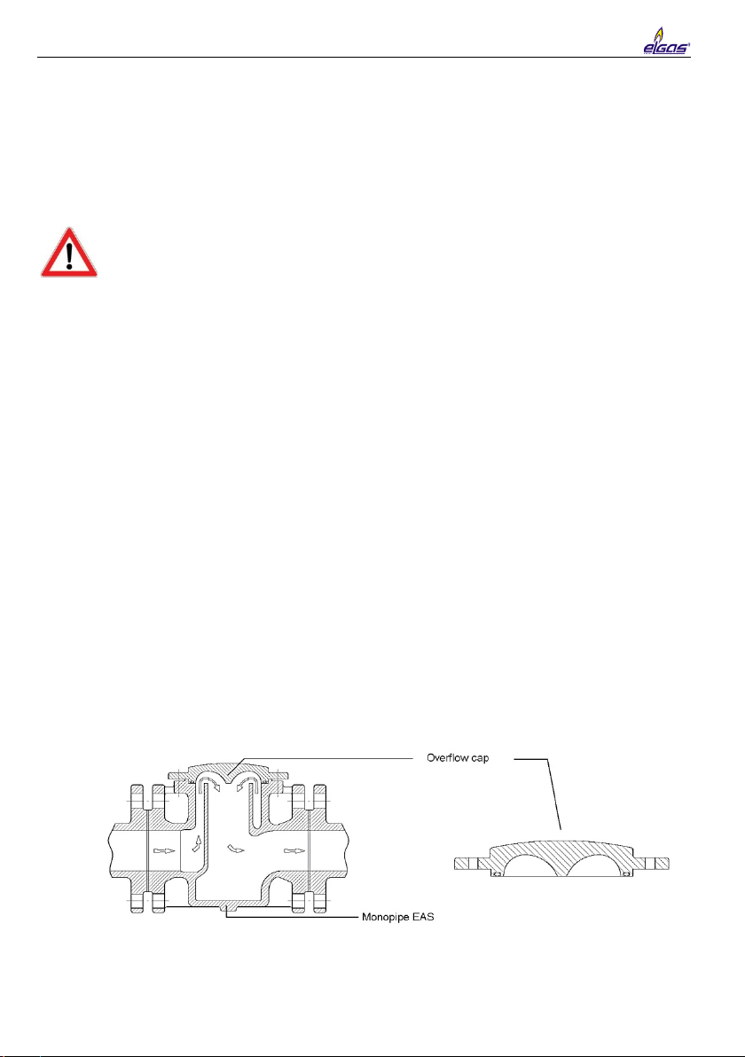
2.2 Cleaning of the pipeline prior to measuring insert installation
Before installing the meter onto the EAS, the pipeline must be cleaned so that no
foreign objects, dust or fluids remain inside.
On request ELGAS, s.r.o. can supply an overflow cap, which allows the gas to flow
through the meter in place of the measuring insert.
The installation of a filter upstream of the meter is recommended.
The pipework can now be flushed, so that excess dirt is expelled without damaging
5
the measuring insert.
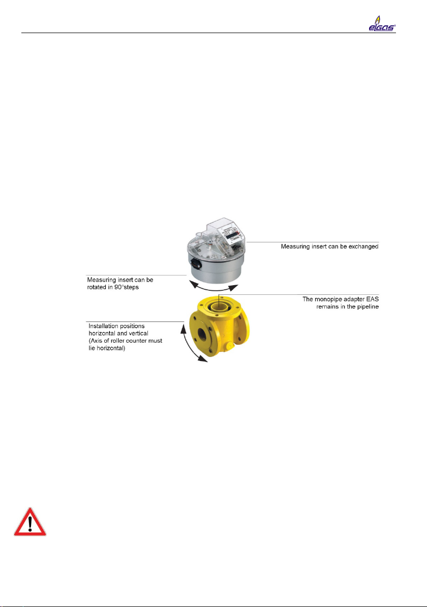
2.3 Installing the meter onto the monopipe adapter EAS
Prior to the installation of the meter, the measuring insert should be inspected to
ensure that no damage has been inflicted on the meter during transportation.
Accessories should be inspected for completeness (e.g. Pulse generator). Faulty
components should be replaced.
The measuring insert is delivered in special protective packaging. This should only
be removed shortly before installation.
Installationof the meteris possible horizontallyor vertically (if over-run brakeis applied,
only horizontal position with counter on top is allowed); the meter head can be rotated
in 90° steps. It should however, always be ensured that the axis of the roller counter is
horizontal (i.e. volume value can be read). The meter must not be installed upside
down.
Before mounting the meter onto the EAS, make sure that the pipeline has been
flushed and is clean. If not please refer to section 2.2 "Cleaning of the pipeline prior
to measuring insert installation".
The gas should be dry and free of dirt and dust. Particles may not be larger than
5Microns. Otherwise, we urgently recommend the installation of a dust-moisture trap.
In case of new systems, the temporary installation of a filter or cone screen (mesh
width: 0,5 mm) is recommended in order to protect the meter. The cone screen
should be removed after 4 weeks.
The O-rings mounted on the meter must be firmly seated and must not be damaged
during installation.
The meter is mounted to the EAS by tightening the cylinder screws is a crosswise
manner. Please keep to the recommended tightening torque:
Nominal Diameter DN 50 = 40 Nm
Nominal Diameter DN 80 = 65 Nm
Nominal Diameter DN 100 = 100 Nm
Only the ELGAS, s.r.o. delivered screws may be used for this purpose.

6
After installation of the meter a leak test must be carried out on the entire unit.
To prevent sabotage and leakage through the loss of screws the meter can be
sealed.
2.4 Pulse generators
For the remote transmission of operating volume, the following
pulse generators are available:
•NF (IPG-NF1/2) Reed-contact (Standard)
pulse value = 1m3 per pulse
For use within explosive sensitive areas with gas, steam and mist
II 2G EEx ia IIC T6
The intrinsic safety can only be guaranteed with the correct operating materials,
together with the written confirmation/proof of intrinsic safety and the verified
following maximum values.
Umax = 24 VDC
Imax = 10 mA Pmax
f
max
=
=
120 mW
0.18 Hz
Ci
effective internal capacity
= negligibly small
Li
effective internal inductivity
= negligibly small
•MF Namur Sensor (optional)
pulse value = 1m3 per 100 pulses
For use within explosive sensitive areas with gas, steam and mist
II 2G EEx ia IIC T6
The intrinsic safety can only be guaranteed with the correct operating materials,
together with the written confirmation/proof of intrinsic safety and the verified
following maximum values.
U
max
=
25 VDC
I
Mark
=
>2.2 mA
f
max
=
18 Hz
U
Nom
=
8 VDC
I
Space
=
<1.0 mA
Ci
effective internal capacity
=
<=30 nF
I
max
=
4 mA
P
max
=
100 mW
Li
effective internal inductivity
=
<=100 µH
•NF Reed-contact IN-Z61 (optional)
pulse value = 1m3per pulse
This reed pulser can be retrofitted at later time without
breaking the meter seal.
Note: This pulser is only designed for an ambient
temperature of -10 °C to 50 °C.
For use within explosive sensitive areas with gas, steam and mist
EEx ia IIC/IIB/IIA EEx ib IIC/IIB/IIA

7
The intrinsic safety can only be guaranteed with the correct operating materials,
together with the written confirmation/proof of intrinsic safety and the verified
following maximum values.
2.5 Electrical connection of pulse generator
The electrical connections for the two pulse generators NF Reed-contact and MF
Namur Sensor in the register area is made possible by a 6-pole circular plug.
The NF Reed-contact and MF Namur Sensor (if installed) are indicated by a sticker,
which is positioned on the outer casing of the measuring insert.
Pulse generator sticker for NF-Reed contact
(Low
frequency)
Pulse generator sticker for MF-Namur Sensor (Middle
frequency)
In addition to the type description on each sticker, information about the number of
pulses per m3 (pulse value), the Ex-identification number of the pulse generator and
the permissible maximum electrical values are displayed.
The cable is correctly connected when the circular plug is inserted into the socket
and is fastened by tightening the coupling ring.
The NF Reed-contact IN-Z61 has its own direct connection point and is indicated on
the sensor. The plug is pushed as far into the opening of the housing, until the
connecting point engages. With an additional pin, the plug is secured before
removing it again. The pin has a diagonal hole in it through which wire is placed to
seal the pulse generator.
Only the original supplied plug connection may be used for this purpose.
3 Commissioning
Fill the measuring section slowly by opening valves gradually(at least 1 minute) until
the operating pressure is reached.
Note: Pressure surges (shocks) and / or excessive start-up flowrates may damage
the meter.
Umax = 25 VDC
Imax = 50 mA Pmax = 250 mW
fmax = 0.18 Hz
Ci
effective internal capacity
= negligibly small
Li
effective internal inductivity
= negligibly small
8
The maximum flowrate Qmax of the meter may not be exceeded.
Carry out a leak test.
Please take note of the maximum and minimum flowrates indicated on the typeplate
of the meter.
3.1 Maintenance and service centre
TRZ, EQZ and EQZK have permanently lubricated bearings. Lubrication of the
bearings is not necessary.
Service centre:
ELGAS, s.r.o., Provozovna Chrudim, Pardubicka 199, 537 01 Chrudim,
Czech republic, Tel.: +420 469 623 087, Email.: sales@elgas.cz
4 Disassembly and disposal
To disassemble the gas meter measuring insert from the monopipe adapter the
4 cylinder screws must be unscrewed. Until such time that a new measuring insert
can be installed, use can be made of the over-flow cap which is fastened to the
EAS. The flow is therefore ensured during the interim.
For revisions, it is advisable to return these to the manufacturer in the original
packaging or to the closest service centre.
Meters, which are to be retired from service, can be sent to ELGAS, s.r.o. or the
nearest service centre or in addition be sent for scrap metal use.
5 Information for installation in explosive areas
Markings on the complete meter as an explosion proof operating device:
for TRZ: Ex II -/2G IIB T4X Tamb -10 °C ... 55 °C
for EQZ/EQZK: Ex II -/2G IIB T4X Tamb -10 °C ... 60 °C
The regulations for explosion proof applications for the pulse generators are
described in detail in this manual in Chapter 2.4.
If the optional pulse generator IN-Z61 is used, then the ambient temperature
may
not fall outside the stipulated range of -10 °C ... 50 °C.
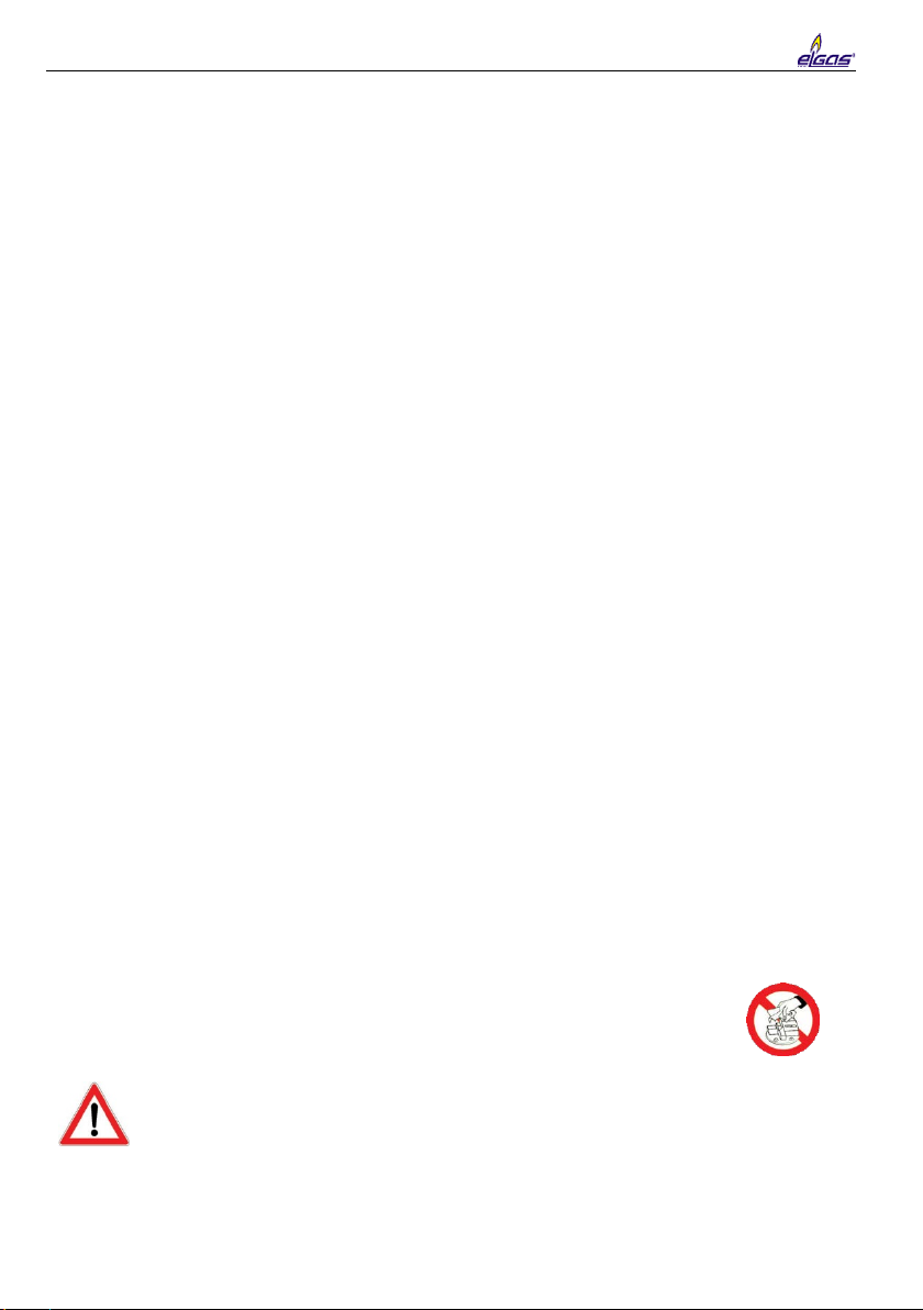
Cleaning of the register cover with a dry tissue/cloth
must be strictly avoided. Danger of contact -
brush discharge i.e. sparks may occur during contact.
Where the danger exists of falling objects the pressure connection pr, the connection
plug for the electrical connection and the optional pulse generator INZ-61 should
be protected by a protective covering. Otherwise the danger exists that an impact
on the pressure connection pr, a leak could be caused. By impact on the register
covering, the danger exists that the mounted plug or IN-Z61 electrical components
could be destroyed leading to
sparks. Such protective coverings for each nominal
size can be sourced from ELGAS, s.r.o.. Other protective coverings may also be
9
used provided that they meet the above mentioned requirements.
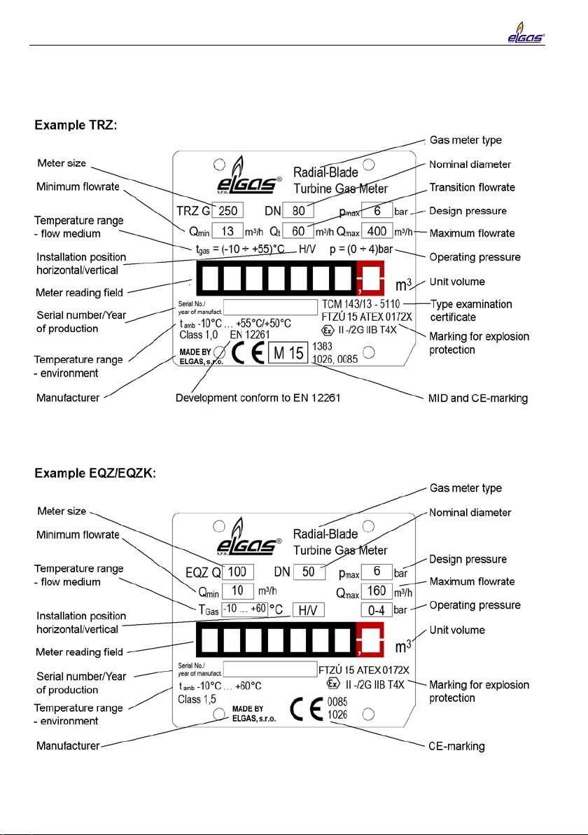
6 Detailed description - type plate
10
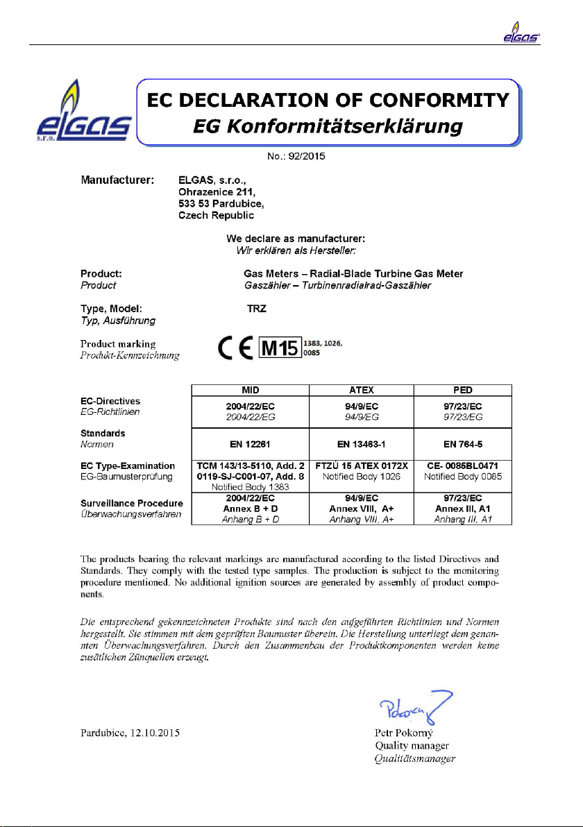
7 Declaration of Conformity
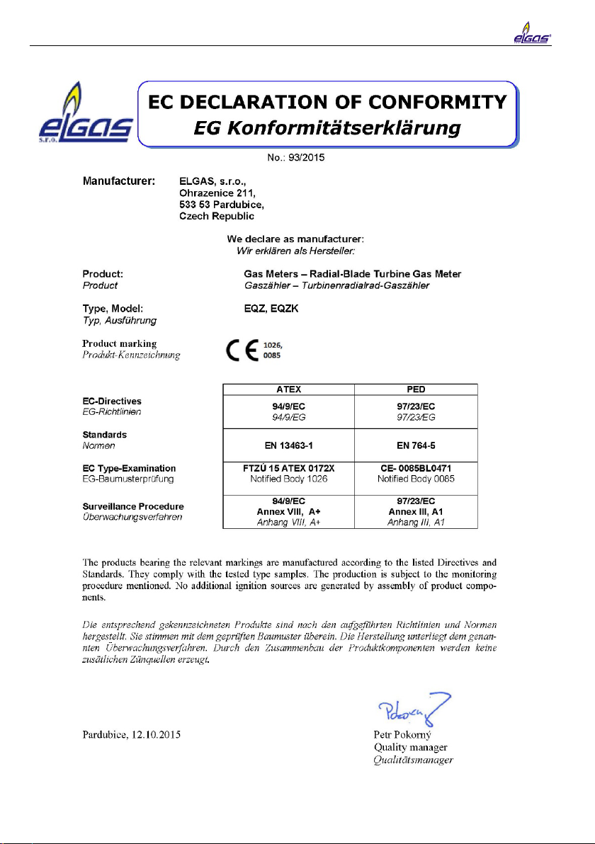
11

Radial-blade turbine gas meter TRZ
Radial-blade turbine quantometer EQZ/EQZK
Installation and operating instructions
Prepared by:
Collective of authors
Issued by:
ELGAS, s.r.o
Ohrazenice 211
533 53 Pardubice
Czech republic
Phone: +420 466 414 500. 511
Fax: +420 466 411 190
http://www.elgas.cz
e-mail: sales@elgas.cz
Issued on:
May 2018
Rev. no.:
Rev. 1
This manual suits for next models
2
Table of contents
Popular Measuring Instrument manuals by other brands

Microsensor
Microsensor MPM480 Operation manual

Rapsodo
Rapsodo HITTING 2.0 quick start guide

Bender
Bender RCMB-35-30 Series quick start guide

Tektronix
Tektronix KEITHLEY 4200A-SCS-PK2 quick start guide

VIDA TECH
VIDA TECH F7021 installation manual

Keysight Technologies
Keysight Technologies UXA N9040B manual


