manuals.online logo
Brands
  1. Home
  2. •
  3. Brands
  4. •
  5. Amprobe
  6. •
  7. Measuring Instrument
  8. •
  9. Amprobe AT-2005-A User manual

Amprobe AT-2005-A User manual

This manual suits for next models

2

Other Amprobe Measuring Instrument manuals

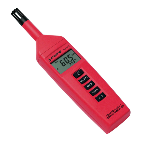
Amprobe THWD-3 User manual

Amprobe

Amprobe THWD-3 User manual

Amprobe SOLAR-100 User manual

Amprobe

Amprobe SOLAR-100 User manual

Amprobe LT-10 User manual

Amprobe

Amprobe LT-10 User manual

Amprobe TMD Series User manual

Amprobe

Amprobe TMD Series User manual

Amprobe MEGATEST 5000 User manual

Amprobe

Amprobe MEGATEST 5000 User manual

Amprobe MANO2-A User manual

Amprobe

Amprobe MANO2-A User manual

Amprobe TMA40 User manual

Amprobe

Amprobe TMA40 User manual

Amprobe ACD-21SW User manual

Amprobe

Amprobe ACD-21SW User manual

Amprobe VP-600SB User manual

Amprobe

Amprobe VP-600SB User manual

Amprobe AD40B User manual

Amprobe

Amprobe AD40B User manual

Amprobe VP-440 User manual

Amprobe

Amprobe VP-440 User manual

Amprobe AC50A User manual

Amprobe

Amprobe AC50A User manual

Amprobe ECB50A User manual

Amprobe

Amprobe ECB50A User manual

Amprobe TH-1 User manual

Amprobe

Amprobe TH-1 User manual

Amprobe TMA40-A User manual

Amprobe

Amprobe TMA40-A User manual

Amprobe ACD-3300 IND User manual

Amprobe

Amprobe ACD-3300 IND User manual

Amprobe MAN02-A User manual

Amprobe

Amprobe MAN02-A User manual

Amprobe AMB-45 User manual

Amprobe

Amprobe AMB-45 User manual

Amprobe ACD - 50NAV User manual

Amprobe

Amprobe ACD - 50NAV User manual

Amprobe MT-10 User manual

Amprobe

Amprobe MT-10 User manual

Amprobe TIC 300 PRO User manual

Amprobe

Amprobe TIC 300 PRO User manual

Amprobe LM-120 User manual

Amprobe

Amprobe LM-120 User manual

Amprobe WT-50 User manual

Amprobe

Amprobe WT-50 User manual

Amprobe CR50A User manual

Amprobe

Amprobe CR50A User manual

Popular Measuring Instrument manuals by other brands

Powerfix Profi 278296 Operation and safety notes

Powerfix Profi

Powerfix Profi 278296 Operation and safety notes

Test Equipment Depot GVT-427B user manual

Test Equipment Depot

Test Equipment Depot GVT-427B user manual

Fieldpiece ACH Operator's manual

Fieldpiece

Fieldpiece ACH Operator's manual

FLYSURFER VIRON3 user manual

FLYSURFER

FLYSURFER VIRON3 user manual

GMW TG uni 1 operating manual

GMW

GMW TG uni 1 operating manual

Downeaster Wind & Weather Medallion Series instruction manual

Downeaster

Downeaster Wind & Weather Medallion Series instruction manual

Hanna Instruments HI96725C instruction manual

Hanna Instruments

Hanna Instruments HI96725C instruction manual

Nokeval KMR260 quick guide

Nokeval

Nokeval KMR260 quick guide

HOKUYO AUTOMATIC UBG-05LN instruction manual

HOKUYO AUTOMATIC

HOKUYO AUTOMATIC UBG-05LN instruction manual

Fluke 96000 Series Operator's manual

Fluke

Fluke 96000 Series Operator's manual

Test Products International SP565 user manual

Test Products International

Test Products International SP565 user manual

General Sleep Zmachine Insight+ DT-200 Service manual

General Sleep

General Sleep Zmachine Insight+ DT-200 Service manual

Sensa Core Lacto Spark user manual

Sensa Core

Sensa Core Lacto Spark user manual

VOLTCRAFT UTS-1980 operating instructions

VOLTCRAFT

VOLTCRAFT UTS-1980 operating instructions

EBCHQ 94915 Operation manual

EBCHQ

EBCHQ 94915 Operation manual

Balluff BIP LD2-T017-01-EP-S4 Series user guide

Balluff

Balluff BIP LD2-T017-01-EP-S4 Series user guide

Pulsar IMP Lite Series instruction manual

Pulsar

Pulsar IMP Lite Series instruction manual

ETCR 6800 user manual

ETCR

ETCR 6800 user manual

manuals.online logo
manuals.online logoBrands
  • About & Mission
  • Contact us
  • Privacy Policy
  • Terms and Conditions

Copyright 2025 Manuals.Online. All Rights Reserved.

Use R2000 & S2600-A (LSGs)
1. Plug the alligator clip cordset into the
LSG and connect one clip to ground.
2. Connect the other clip to one terminal
of a battery (at least 9V).
3. Using a separate jumper, connect the
other battery terminal to the faulted
wire.
4. Set the R2000 to the ‘SHORT’ mode
and adjust the sensitivity and range
switch until 8–9 LEDs are displayed.
5. Trace the wire. The fault will be at the
point where you begin to lose the
signal.
Advanced Wire Tracer
AT-2000-A Series
The AT-2000-A series consists of individual components with unique capabilities. This label describes the capabilities
of the complete system (AT-2005-A). Any other system in this series can be upgraded to include all of these
capabilities by simply purchasing the additional components.
CAUTION: Always verify that the voltage presence is not beyond the range of the instrument. 300V Max
Locating Ground Faults
A ground fault is a direct connection of the conductor to ground. A typical ground fault may cause a tripped circuit
breaker or a blown fuse ( in contrast to an ‘open’, which passes no current). In this situation, the B2024 battery
can be used as the current source. The high voltage from the B2024 will overcome a high resistance fault and will
produce a stronger signal. Also, you can use line voltage as the power source by connecting the S2600-A across the
breaker.
LSG
Fig. 2 Locating
Ground Faults
Identifying Circuit Breakers
Use R2000 & S2600-A (LSGs)
1. For 110V receptacle, connect pigtail cordset to LSG and plug into receptacle; for other voltages or connections,
use the Alligator-clip cordset.
2. The light will blink if connection is
correct.
3. Set the R2000’s range to x1; mode to
‘SHORT’, and thumbwheel to around 5.
4. Hold R2000 near LSG to verify its
operation.
5. At the breaker panel, pass the R2000
over the load side of each breaker,
always reducing the sensitivity when
more than 9 LEDs are lit.
6. The strongest signal indicates the
proper breaker.
LSG
LSG
R2000
OR
Fig. 1 Identifying Circuit Breakers
Amprobe®
www.Amprobe.com
[email protected]
Everett, WA 98203
Tel: 877-AMPROBE (267-7623)
Amprobe®Europe
Beha-Amprobe
In den Engematten 14,
79286 Glottertal, Germany
Tel.: +49 (0) 7684 8009 - 0
P/N 2757342 Rev 002
11/2013 6001648 A
©2013 Amprobe®Test Tools. All rights reserved.
Locating Opens
Use the R2000 & T2200
1. Plug the alligator clip cordset into the
T2200 and attach one clip to a separate
ground and the other to the wire.
2. Where possible, ground any adjacent
wires.
3. Set the T2200 to ‘HIGH’.
4. Set the R2000 to the ‘OPEN’ mode (use
the ‘SHORT’ mode if wire is in moist
soil). Adjust the sensitivity and range
switch until 8–9 LEDs are displayed.
5. Trace the wire. The open will be at
the point where you begin to lose the
signal.
Tracing Energized Wires
from the Panel to a Load
Use R2000, T2200, A2201, B2024 (optional).
1. Plug the A2201 and the B2024 into the
T2200.
2. Set the T2200 to ‘HIGH’.
3. Set the R2000 to ‘OPEN’ mode and adjust
the sensitivity and range switch until 8–9
LEDs are displayed.
4. Place the clamp around the energized
wire. Make sure it’s the ‘HOT’ wire only.
5. Trace the wire to identify the loads. You
may alternate between ‘OPEN’ and
‘SHORT’ mode and adjust the sensitivity
and range switch, as needed, to improve
signal detection.
Locating Shorts
Use R2000 & T2200
1. Plug the alligator clip cordset into the T2200. Set the T2200 to ‘LOW’ mode.
2. Attach one clip to one of the shorted wires and the other clip to the other wire.
3. Turn T2200 ‘ON’.
4. Set the R2000 to the ‘SHORT’ mode and adjust the sensitivity and range switch until 8–9 LEDs are displayed.
5. Trace the wire. The short will be at the point where you begin to lose the signal.
Identifying Wires in a Bundle
For energized wires, follow procedure under ‘Tracing Energized Wires’. At the bundle, separate the individual wires
from each other with your fingers to determine which wire is producing the signal.
For non-energized wires, follow the procedure under ‘Locating Opens’, and proceed as above.
R2000
T2200
Signal No Signal
Fig. 3 Tracing Open Wires
R2000
LSG
AD-1
No SignalSignal
Panel
Box
C2902
Cord Set
To Transformer
Fig. 4 Tracing
Energized Wires Tracing Energized Wires from
a Load to the Panel
Use R2000 & S2600-A (LSGs).
1. Plug the alligator clip cordset into the LSG.
2. Connect one clip to the ground separate
from the wire to be traced (the ‘HOT’ wire).
3. Connect the other clip to the ‘HOT’ wire (at a
110V outlet, you can use the AD-1 adapter).
4. Set the R2000 to the ‘SHORT’ mode and
adjust the sensitivity and range switch until
8–9 LEDs are displayed.
5. Trace the wire.
T2200
B2024
A2201
Fig. 5
Tracing
Downstream
Loads