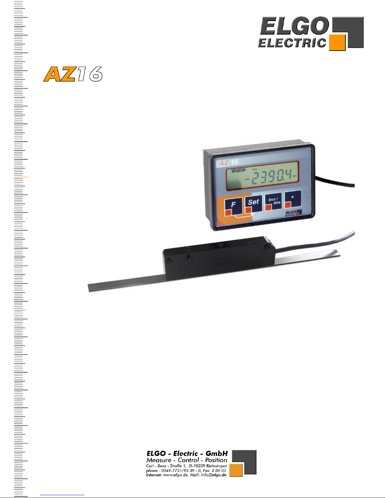
ELGO Electric AZ16E Series User manual
E series
Installation manual
AZ16E-000-E_10-06.doc Doku Art. Nr. 799000026
Battery powered Absolute Linear Encoder System
Complete with an Indicator and an external Magnet Sensor with 0.1 mm resolution
Features
• Measuring distances up to 8 meters possible
• Unique definition of the zero point
(no further referencing necessary)
• Permanent retention of all data and settings
• Reserve energy up to 3 years
• AUTO-POWER-OFF function with adjustable „switch on“ time
• Switch over for absolute / incremental mode
• Millimeters or Inches operation
• Fraction views in the Inch mode possible
• User friendly menu levels
• Keys can be enabled or disabled individually
• Adjustable reference value and 3 tool offsets
• Symbols individually selectable (mm/inches/arrows etc.)

2
1. INTRODUCTION 3
2. SAFETY 3
3. DETERMINATION OF THE RAIL AND TAPE LENGTH 4
4. DISPLAY ASSIGNMENT 4
5. THE AZ16E IN OPERATION 4
5.1 Initial operation 4
5.1.1 Detection of measuring direction 4
5.1.2 Referencing 4
5.3 Parameter settings 6
5.4 Parameter list 7
6. BATTERY CHANGE 8
7. MAGNETIC TAPE 9
7.1 Handling 9
7.2 Processing note for sticking 10
7.3 Resistance to chemicals of the magnetic tape 10
7.4 Sticking and cutting 10
8. TECHNICAL SPECIFICATIONS 11
9. DIMENSIONS 12
9.1 Display Unit: 12
9.2 External Magnet Sensor „AZS“: 13
10. INSTALLATION / DISPLAY UNIT 13
11. TYPE DESIGNATION 14
12. LIABILITY EXCLUSION / GUARANTEE 15

3
1. Introduction
The new linear „Absolute“ encoder and indicator unit AZ16 is based on the proven magnetic
measuring principle. According to its battery supply, no wirings are necessary and the systems
is able to operate as a complete stand alone unit. The max. possible measuring distance
amounts to 8 meters. By using the AUTO-POWER-OFF mode the max. service life span of the
battery amounts up to 3 years.
The external magnetic sensor is connected fix to the indicator by a drug chain suitable cable.
Further a version with an internal sensor and a guidance rail is available (AZ16I).
Characteristics of the AZ16E (external Sensor):
The system consists of
- an extensive programmable Display unit
- the external Magnet Sensor "AZS", which its cable length is available up to 20 meters
- an absolute coded Magnetic Tape with a max. measuring Length of 8 meters
The AZS sensor is contactlessly moved over the magnetic tape. It is resistant against abrasion,
dust, dirt and water (protection class IP 67).
The user must provide and guarantee for a suitable mechanical guiding system, to guide the
sensor and keep it along the whole movement in the correct distance (0... 1.5 mm) to the
magnetic tape. The sensor must be installed coplanar to the tape.
2. Safety
Please note: Before first commissioning read this installation manual carefully and
observe absolutely the installation instructions. The measuring system is only dedi-
cated for recording lengths. The type label is intended for exact identification of the
measuring system. The label is situated on the indicator housing. It informs about
the exact type designation (see chapter 9), the delivery date and the production
number. When contacting the company ELGO Electric GmbH please use these
terms.
Attention!
The company ELGO Electric GmbH is not liable for possible damages to machines
and or to persons, which can result from defective material at the measuring sys-
tem and the following circuit. The machine manufacturer is responsible for taking
and realizing the necessary safety precautions.
4
3. Determination of the rail and tape length
Basically the following applies with an order of magnetic tape:
Ordered length of tape = effective measuring distance + 100 mm
For further details see the „Type designation“ at the end of the manual.
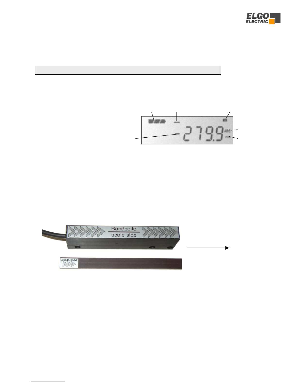
4. Display assignment
5. The AZ16E in operation
5.1 Initial operation
5.1.1 Detection of measuring direction
The Magnet Sensor „AZS“ and the magnetic tape are provided with a marker, in order to signal
the installation direction. The markings of sensor and tape must point to the same direction.
The counting direction (+/-) is reversible in parameter P01 (see chapter 5.4).
5.1.2 Referencing
Setting the zero-point: A new AZ16E unit shows always the absolute value of the magnetic
tape and should be calibrated to the zero point for one time. The reference value default setting in
register P09 is 0. To assign a zero point to an arbitrary position, move to the desired
zero-point and press the buttons F + Set together.
Reference value: Alternatively an arbitrary value can be entered in P09, to set a demanded ref-
erence measurement by pressing F + Set together.
battery condition direction arrow tool offset 3 (1, 2 or 3 possible)
absolute mode
sign measurement unit
Sensor bottom Positive Counting Direction
(if P01 = Default setting)
Tape (top view, scanning side)
5
5.2 Basic functions (overview)
Absolute-/ relative measurement
Press Incr/Abs to switch over from „absolute“ to „relative“ measurement:
The actual value shows „0“ and also "INC" appears in the display.
With a renewed pressing of Incr/Abs the display switches back to
„absolute“ measurement and the display shows the real absolute value
again and „ABS“ also.
Incr/
Abs
Reference value
FSet
By pressing F + Set together, the display sets
to the reference value, deposited in register P09.
Switch back from the sleep mode
F
The unit switches into the sleep mode after completion of the adjustable
time in register P04, if there are no changes in the display value and no
key is pressed.
To switch back from the sleep mode, the button Fmust be pressed.
*
Tool offset
Switches over betwee three adjustable Tool Offsets. These can be
depostided in the registers P10/11/12.
The display appears (right above):
, or .
The selectet tool offset will be added to the actual value.
21 3
6
5.3 Parameter settings
Fraction views in Inch- Mode
SET
In the inch mode four different
fraction views can be selected:
Press SET for one time: LSB = 1/64 Inch
Press SET for two times: LSB = 1/32 Inch
Press SET for three times: LSB = 1/16 Inch
Press SET for four times: LSB = 0.001 Inch
F
1) Press button F for 3 seconds.
"P01" (Parameter 01) appears in the display window.
Set
3) Select the desired decade by pressing Set
Incr/
Abs
4) Adjust the desired value by using the Incr/Abs button
F
5) Press F to select the next parameter
Repeat No. 2)... 4) for the next parameter
F
6) Press F for 3 seconds
The display shows the actual value again
F
2) Press button F
The appropriate parameter value appears in the display
3 sec.
3 sec.
7
5.4 Parameter list
P 01 / Configuration of system:
0 =
XXXXX
1 =
Positive counting direction
Negative counting direction
0 =
1 =
mm operation (0.1 mm resolution)
Inch operation (0.1 inches resolution)
0 =
1 =
mm/Inch symbol disabled
mm/Inch symbol enabled
( default setting = 11100 )
0 =
1 =
Arrow symbol for „positive direction“ disabled
Arrow symbol for „positive direction“ enabled
0 =
1 =
LCD in standby mode disabled
LCD in standby mode enabled
(Display "OFF" and battery condition)
P 03 / Decimal place: ( default setting = 1 )
X= 0...3 (for mm operation only)
P 05 / keyboard interlock: ( default setting = 111 )
XXX
0 =
1 =
button Set disabled
button Set enabled
0 =
1 =
button Incr/Abs disabled
button Incr/Abs enabled
0 =
1 =
button *disabled
button *enabled
P 04 / Auto power off time: ( default setting = 10 s )
X= 0...99 seconds ( 0 = standby mode disabled)
X

8
Parameter list (continuation)
P 09 / Reference value: ( default setting = 0.0 mm / 0.000 Inch )
- 999999.9 mm ... + 999999.9 mm ( - 9999.999 Inch ... + 9999.999 Inch )
P 10 / tool offset 1: ( default setting = 10.0 mm / 0.100 Inch )
- 999999.9 mm ... + 999999.9 mm ( - 9999.999 Inch ... + 9999.999 Inch )
P 11 / tool offset 2: ( default setting = 20.0 mm / 0.200 Inch )
- 999999.9 mm ... + 999999.9 mm ( - 9999.999 Inch ... + 9999.999 Inch )
P 12 / tool offset 3: ( default setting = 30.0 mm / 0.300 Inch )
- 999999.9 mm ... + 999999.9 mm ( - 9999.999 Inch ... + 9999.999 Inch )
P 99 / Indicates the software version:
1.21 = SW-V1.21
P 08 / Position scaling factor:
0.001 ... 9.999 (the position value is multiplied by the factor adjusted here)
( default setting = 1.000 )
6. Battery change
To change the battery with a standard unit (integrated battery version) remove battery cover
on the rear, by pressing the outer edges gently (like shown on the photo). Useful are commer-
cial battery types, size C, 1.5 V) with good quality. All values and settings remains in case of
changing the batteries.
Please pay attention to the correct polarity!
The polarity is marked inside the housing.
9
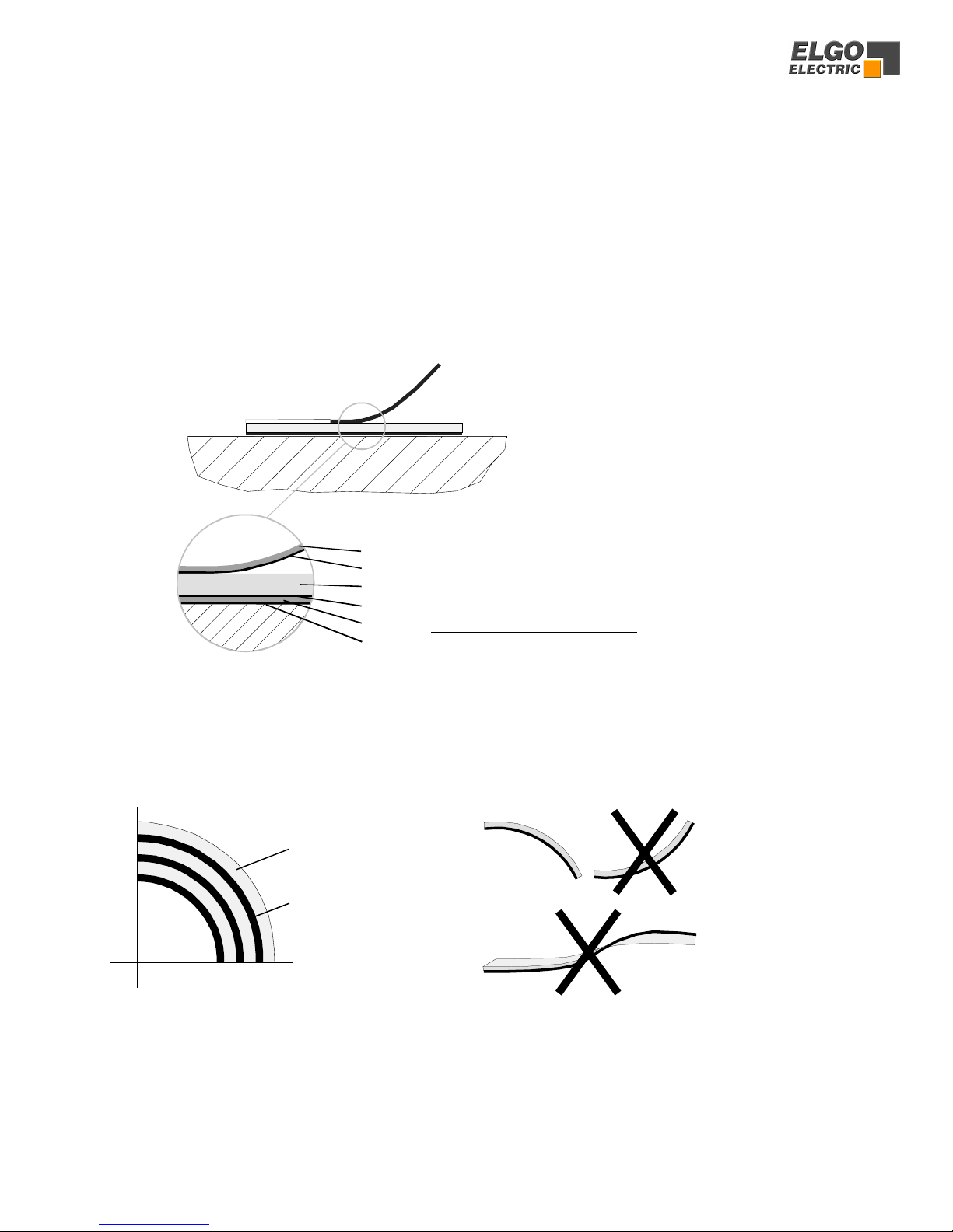
7. Magnetic Tape
The magnetic tape consists of 3 components (see picture 1)
• a magnetized flexible rubber tape (Pos. 3), which is connected factory made with a
• steel band (Pos. 5) and a
• covering band (Pos. 1) , which is intended for the protection of the rubber tape.
• For mechanical protection of the magnetic tape the covering band must be stuck on. Addi-
tionally it protects the magnetic tape from extreme external magnetic influences.
To reach a complete adhesion between the several materials a special sticky tape is used
(Pos. 2, Pos. 4, Pos. 6).
Pos. 1
–
Coverin
g
band
Pos. 2
–
Sticky tape
Pos. 3
–
Ma
g
netic rubber tape
Pos. 4 - Sticky tape
Pos. 5
–
Steel band
Pos. 6 - Sticky tape
Factory
bonded
Picture 1: Components of the magnetic tape
7.1 Handling
To avoid tension in the magnetic tape, don’t tuck or twist it. Avoid also to store or to handle it
with the magnetic rubber tape to the inside (min. bend radius 150 mm).
Magnetized
synthetic tape
Steel band
Picture 2: Storage and transport

10
7.2 Processing note for sticking
The provided sticky tapes stick well on clean, dry and plain surfaces. The more pollution exists
the more proper the surface has to be. A surface roughness of Ra<= 3,2 (Rz<= 25 / N8) is rec-
ommendable. Typical solvent for cleaning surfaces are a 50/50 - isopropyl-alcohol / water mix-
ture or heptane. The surfaces of materials as copper, brass etc. should be sealed to avoid an
oxidation. The stability of the adhesion is directly depending on the contact, which the adhesive
develops to the stuck surfaces. A high pressure results in a good surface contact.
The optimal sticking temperature is between + 21°C and 38°C.
Avoid colder sticking surfaces than + 10 °C, because in this case the adhesive becomes to hard
and perhaps a sufficient immediate adhesion is hardly to achieve. After proper sticking the sta-
bility of the connection is ensured also when the temperature is below zero. The final tackiness
of a sticking is from experience reached after approximately 72 hours (at + 21 °C). For sticking
use only the provided sticky tape.
7.3 Resistance to chemicals of the magnetic tape
The magnetic tape shows no or only small effects when contacting permanently the following
materials after 2 to 5 years: Formic acid, Glycerol 93°C, Linseed oil, Soy beans oil, Cotton seed
oil, N-hexane, Lactic acid, Formaldehyde 40%, Isooctane, Petroleum.
Poor to medium effects result when contacting permanently the following materials after ap-
proximately 1 year: Acetone, Gasoline, Acetic acid 30%, Olein acid, Acetylene, Steam, Acetic
acid, pure Acetic acid, Sea water, Ammonia, Acetic acid 20%, Isopropyl ether, Stearic acid 70°C
anhydrous, Kerosene.
Strong effects result when contacting permanently the following materials after 1 to 5
months: Benzene, Nitric acid 70%, Turpentine, Toluene, Lacquer solvent, Nitric acid red and
Vitriolic, Carbon Tetrachloride, Trichloroethane, Nitrobenzene, Hydrochloric acid 37% and 93°C,
Tetrahydrofuran, Xylene.
7.4 Sticking and cutting
Attention! When sticking the magnetic tape pay attention to the marks on the mag-
netic tape. A faulty installation delivers incorrect values. An already stuck magnetic
tape is ruined after removing and can't be used again. Observe also the counting
direction of the measuring system.
The magnetic tape and the covering band must be cut to the exact length before sticking:
Magnetic tape length = measuring length + 0.1 m
Preferably the magnetic tape should be stuck into a nut or aligned to an edge.
Procedure for sticking:
1. The magnetic tape is already factory bonded with the steel band, in between is a double sided
sticky tape. Stick the provided sticky tape onto the carrier side (= steel band).
2. Now adjust the magnetic tape and stick it onto the surface. The best way to stick the mag-
netic tape is to do it in two steps. Remove the first half of the adhesive film from the sticky tape
and stick it, then do the rest length.
3. Then stick the sticky tape onto the covering band. It is not important on which side of the
covering band the sticky tape is stuck on.
4. Stick the covering band onto the visible brown magnetic rubber tape

11
8. Technical specifications
AZ16E (battery powered absolute encoder and indicator system with an external sensor)
POWER SUPPLY 1 commercial battery size C (1.5 V)
Battery service life 1... 3 years (depends on adjusted switch-on time)
Distance Sensor - Tape max. 1.5 mm
Resolution of encoder 0.1 mm
Measuring units mm’s or INCHES
Measuring length max. 8 m
Principle of Measurement Magnetic, absolute
Character of Measurement Linear, no rotative movements possible
LCD-Display 6 Decades, height = 8 mm, with battery condition, signs and symbols
Keypad Membrane keypad
Operating temperature + 5... + 50° C
Stock temperature 0... 70° C
Humidity Not condensing, max. 80 %
Altitude max. 2000 m above sea level
Protection class (display unit) IP 43 (installed state)
Outer dimensions W x H = 96 x 72 mm
Cut out W x H = 93 x 67 mm
Depth (install depth) 37 mm
(total depth) 43 mm
Protection class (sensor) IP 67
Dimensions of sensor (see drawing on page 13)
Magnetic tape for AZ16
Code Absolute, single track system
Extension coefficient a = 16 x 10-6 K-1
Linear extension ∆L = L x αx∆ϑ (L= measuring length in meters)
Dimensions (W x H) 10 mm x ca. 1.8 mm
min. bend radius 150 mm
Operating temperature 0... + 50° C
Protection class IP 67

12
9. Dimensions
9.1 Display Unit:
Panel cut out: B x H = 93 x 67 mm
96
72
63 9
92
6
27
43
34
5.5
37 (Install depth)
66
* minus 9 mm, plug can be bended
34 *

13
9.2 External Magnet Sensor „AZS“:
10. Installation / Display Unit
For mounting into a panel serves 2 small mount-
ing plates with grub screws (included in the deliv-
ery, see image right).
The unit must be pushed from the front into the
cut-out and fixed from the rear by the grub
screws at the instrument panel then.
100
12
1
25
87
174
4
Ø 3.4 Ø 6
R4
14
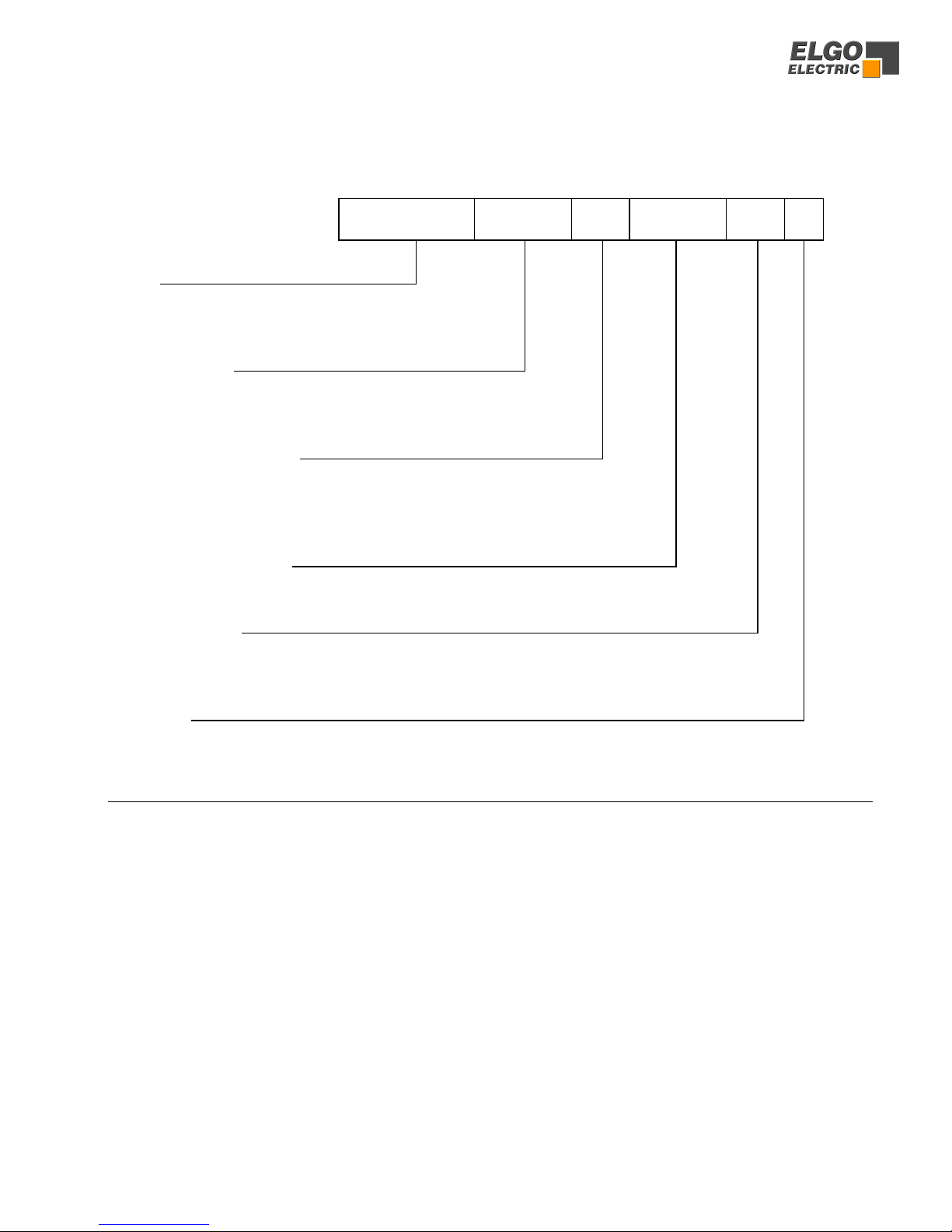
11. Type designation
AZ16E- 000- 1- X
Type
SN- Number
Power supply (1.5 V)
Cable options
AZ16E: Indicator with external sensor
000 = standard
001 = first special version etc.
0 = fixed cable output
1 = plugable by RJ45 connector (standard)
03.0-
Options
1 = one internal size C battery (standard)
2 = two internal size AA batteries
3 = external battery case
Sensor cable lenght
(max. 20 m possible)
1-
AG = built on housing
Magnetic tape for AZ16E
Type: AB20-40-10-1-R-11 - Desired Length* please indicate in X.XX meters
*) Desired length = measuring length + 0.1 m
15
12. Liability exclusion / Guarantee
We have checked the contents of this instruction manual carefully, to the best of our knowledge and
belief for conformity with the described hardware and software. Nevertheless errors, mistakes or
deviations can not be excluded, therefore we do not guarantee complete conformity. Necessary cor-
rections are included in the subsequent editions.
We appreciate your ideas and improvement suggestions very much.
Reprint, duplication and translation, even in extracts, are only allowed with a written authorization
by the company ELGO Electric GmbH. Our objective is to improve our products constantly, therefore
we keep all rights reserved for any technical modifications without any notice.
ELGO Electric does not assume any liability for possible errors or mistakes.
The guarantee period is one calendar years from the date of delivery and includes the delivered unit
with all its components. ELGO Electric GmbH will at its option replace or repair without charge de-
fects at the unit or the included parts, verifiable caused by faulty manufacturing and/or material in
spite of proper handling and compliance to the instruction manual.
Damages verifiably not caused by ELGO-Electric GmbH and due to improper handling are excluded
from any guarantee e.g. by applying faulty voltage, diffusion of liquid into the interior of the engine,
using force, scratching the surface, chemical influences etc.!
Subject to modifications © ELGO Electric GmbH 2006
Table of contents
Other ELGO Electric Media Converter manuals

Popular Media Converter manuals by other brands


HumanTechnik
HumanTechnik S/PDIF Operation instructions

Belden
Belden GRASS VALLEY KUDOSPRO UHD 1100 user manual

Silex technology
Silex technology LAN 3100 operating manual

Analog way
Analog way BROAD SCAN HD BHD930-AG Preliminary user's manual

TR-Electronic
TR-Electronic CMV582M-4096/4096 PB 36ZB10FL Assembly instructions

Canary
Canary CFT-206X Product specifications