Eli Ezer ERK 7800 User manual

1
R
Re
ef
fr
ra
ac
ct
to
om
me
et
te
er
r/
/K
Ke
er
ra
at
to
om
me
et
te
er
r
E
ER
RK
K
7
78
80
00
0

2
O
Op
pe
er
ra
at
ti
io
on
n
M
Ma
an
nu
ua
al
l
IMPORTANT NOTICE
This product is always protected whbaen you connect the power supply must be
connected to ground included.
The ERK 7800 is classified as Class I.
- Degree of protection against electric shock ; Type B Applied part
- Degree of protection against ingress of water level : None
- Mode of operation : Continuous operation
A Class I is a product in which the protection against electric shock does not rely on
basic insulation only, but which includes an additional safety precaution in such a way
that means are provided for the connection of the product to the protective (ground)
conductor in the fixed wiring of the installation in such a way that accessible metal parts
cannot become live in the event of a failure in the basic insulation.
Use a power outlet which is equipped with a grounding terminal.
This product may malfunction due to electromagnetic waves caused by portable
personal telephones, transceivers, radio-controlled toys, etc.
Be sure to avoid having objects such as, which affect this product, brought near the
product.
It should be used under the supervision of medical staff of hospital
The information in this publication has been carefully checked and is believed to be
entirely accurate at the time of publication. ERK 7800 assumes no responsibility,
however, for possible errors or omissions, or for any consequences resulting from the
No use of the information contained herein.
ERK 7800 reserves the right to make changes in its products or product specifications
at any time and without prior notice, and is not required to update this documentation to
reflect such changes.
Under copyright laws, this manual may not be copied, in whole or in part, without the prior written
consent of ERK 7800

3
R
Re
ef
fr
ra
ac
ct
to
om
me
et
te
er
r/
/K
Ke
er
ra
at
to
om
me
et
te
er
r
E
ER
RK
K
7
78
80
00
0
SAFETY INFORMATION
Accessory equipment connected to the analog and digital interfaces must be certificated
according to the respective IEC/EN standards (e.g. IEC/EN 60950 for data processing
equipment and IEC/EN 60601-1 for medical equipment). Furthermore all configurations shall
comply with the system standard EN 60601-1-2:2007. If you connect additional equipment to
the signal input or signal output of this device, then you are configuring a medical system, and
are therefore responsible that the system complies with the requirements of the system
standard EN 60601-1-1:2001. If in doubt, consult the technical service department or your local
representative.
For EU Countries
The following mark, the name & address of the EU Representative shows compliance of the
instrument with Directive 93/42/EEC.
ISO 15004
This report provides information about the hazard to the examinee’s eyed in compliance
with ISO 15004-1:2006, ISO 15004-2:2007 Ophthalmic instruments –Fundamental
requirements and test methods Part2–Light hazard protection. This condition is satisfied
even when the instrument is operating at maximum light intensity and maximum aperture!
(Maximum intensity is the highest brightness the instrument is capable of delivering,
including the highest brightness achievable if overvoltage is provided) detailed radiation
information at normal usage of this instrument is like bellows.
Radiation output: below 117.1 μW/cm2 Limit by ISO15004: 100 mW/cm2
Number
Radiation output [μW/cm2]
1
107.0
2
117.1
3
115.5
4
115.7
5
103.6
6
103.7
7
108.8
8
109.0
9
105.6
10
105.8
average
109.1
0120

4
O
Op
pe
er
ra
at
ti
io
on
n
M
Ma
an
nu
ua
al
l
SYMBOLS
Symbol
Descriptions
TYPE B EQUIPMENT
Protective earth (ground)
Alternating current
Off (power: disconnected from mains)
On (power: connection to mains)
Do not dispose of inappropriately
Risk of electric shock
Crushing hazard sign
Hand hazard sign
Instruction for user manual
General mandatory action sign
General prohibition sign
General warning, caution sign
Keep dry symbol
DO NOT use hooks symbol

5
R
Re
ef
fr
ra
ac
ct
to
om
me
et
te
er
r/
/K
Ke
er
ra
at
to
om
me
et
te
er
r
E
ER
RK
K
7
78
80
00
0
Fragile symbol
Recycling symbol
Handle with care symbol
This way up symbol
Manufacturer
Manufacturing date

6
O
Op
pe
er
ra
at
ti
io
on
n
M
Ma
an
nu
ua
al
l
GENERAL SAFETY INFORMATION
If you see any warnings or cautions printed on the warning labels, follow the safety
instructions in this manual. Ignoring such cautions or warnings while handling the
product may result in injury or accident. Be sure to read and fully understand the
manual before using this product.
Keep this manual in an easy-to-access place.
Safety Symbols and sign
This indicates hazardous situations which may result in electrical shock to you.
This indicates hazardous situations which may result in crush your hand.
This indicates hazardous situations which may result insert your hand.
This indicates hazardous situations which may result in minor injury to you or others, or may
result in machine damage.
This indicates a mandatory action. If you do not act accordingly, this may result in death or
serious injury to you or others.
This indicates a hazardous situation which could result in death or serious injury to you or
others.
NOTE
This is used to emphasize essential information. Be sure to read this information to avoid
incorrect operation.

7
R
Re
ef
fr
ra
ac
ct
to
om
me
et
te
er
r/
/K
Ke
er
ra
at
to
om
me
et
te
er
r
E
ER
RK
K
7
78
80
00
0
INDEX
IMPORTANT NOTICE ∙ ∙ ∙ ∙ ∙ ∙ ∙ ∙ ∙ ∙ ∙ ∙ ∙ ∙ ∙ ∙ ∙ ∙ ∙ ∙ ∙ ∙ ∙ ∙ ∙ ∙ ∙ ∙ ∙ ∙ ∙ ∙ ∙ ∙ ∙ ∙ ∙ ∙ ∙ ∙ ∙ ∙ ∙ ∙ ∙ ∙ ∙ ∙ ∙ ∙ ∙ ∙ ∙ ∙ ∙ ∙ ∙ ∙ 1
SAFETY INFORMATION ∙∙∙ ∙ ∙ ∙ ∙ ∙ ∙ ∙ ∙ ∙ ∙ ∙ ∙ ∙ ∙ ∙ ∙ ∙ ∙ ∙ ∙ ∙ ∙ ∙ ∙ ∙ ∙ ∙ ∙ ∙ ∙ ∙ ∙ ∙ ∙ ∙ ∙ ∙ ∙ ∙ ∙ ∙ ∙ ∙ ∙ ∙ ∙ ∙ ∙ ∙ ∙ ∙ ∙ ∙ ∙ ∙2
SYMBOLS ∙ ∙ ∙ ∙ ∙ ∙ ∙ ∙ ∙ ∙ ∙ ∙ ∙ ∙ ∙ ∙ ∙ ∙ ∙ ∙ ∙ ∙ ∙ ∙ ∙ ∙ ∙ ∙ ∙ ∙ ∙ ∙ ∙ ∙ ∙ ∙ ∙ ∙ ∙∙ ∙ ∙ ∙ ∙∙ ∙ ∙ ∙ ∙∙ ∙ ∙ ∙ ∙∙ ∙ ∙ ∙ ∙∙ ∙ ∙ ∙ ∙ ∙ ∙ ∙ ∙ ∙ ∙ ∙ ∙ ∙3
GENERAL SAFETY INFORMATION ∙ ∙ ∙ ∙ ∙ ∙ ∙ ∙ ∙ ∙ ∙ ∙ ∙ ∙ ∙ ∙ ∙ ∙ ∙ ∙ ∙ ∙ ∙ ∙ ∙ ∙ ∙ ∙ ∙ ∙ ∙ ∙ ∙ ∙ ∙ ∙ ∙ ∙ ∙ ∙ ∙ ∙ ∙ ∙ ∙ ∙ ∙ ∙ ∙5
1. Features and Intended Use ∙∙ ∙ ∙ ∙ ∙ ∙ ∙ ∙ ∙ ∙ ∙ ∙ ∙ ∙ ∙ ∙ ∙ ∙ ∙ ∙ ∙ ∙ ∙ ∙ ∙ ∙ ∙ ∙ ∙ ∙ ∙ ∙ ∙ ∙ ∙ ∙ ∙ ∙ ∙ ∙ ∙ ∙ ∙ ∙ ∙ ∙ ∙ 8
2. Notes for Using the Instrument ∙ ∙ ∙ ∙ ∙ ∙ ∙ ∙ ∙ ∙ ∙ ∙ ∙ ∙ ∙ ∙ ∙ ∙ ∙ ∙ ∙ ∙ ∙ ∙ ∙ ∙ ∙ ∙ ∙ ∙ ∙ ∙ ∙ ∙ ∙ ∙ ∙ ∙ ∙ ∙9
3. Prerequisites for safety∙∙ ∙ ∙ ∙ ∙ ∙ ∙ ∙ ∙ ∙ ∙ ∙ ∙ ∙ ∙ ∙ ∙ ∙ ∙ ∙ ∙ ∙ ∙ ∙ ∙ ∙ ∙ ∙ ∙ ∙ ∙ ∙ ∙ ∙ ∙ ∙ ∙ ∙ ∙11
4. Introduction ∙∙∙∙∙∙∙ ∙ ∙ ∙ ∙ ∙ ∙ ∙ ∙ ∙ ∙ ∙ ∙ ∙ ∙ ∙ ∙ ∙ ∙ ∙ ∙ ∙ ∙ ∙ ∙ ∙ ∙ ∙ ∙ ∙ ∙ ∙ ∙ ∙ ∙ ∙ ∙ ∙ ∙ ∙ ∙ ∙ ∙ ∙ ∙ ∙ ∙ ∙ ∙ ∙ ∙ ∙ ∙ ∙ ∙ ∙12
4.1 Front side of body ∙ ∙ ∙ ∙ ∙ ∙ ∙∙∙∙ ∙ ∙ ∙ ∙ ∙ ∙ ∙ ∙ ∙ ∙ ∙ ∙ ∙ ∙ ∙ ∙ ∙ ∙ ∙ ∙ ∙ ∙ ∙ ∙ ∙ ∙ ∙ ∙ ∙ ∙ ∙ ∙ ∙ ∙ ∙ ∙ ∙ ∙ ∙ ∙ 12
4.2 Back side of body ∙ ∙ ∙ ∙ ∙ ∙ ∙ ∙ ∙ ∙ ∙ ∙ ∙ ∙ ∙ ∙ ∙ ∙ ∙ ∙ ∙ ∙ ∙ ∙ ∙ ∙ ∙ ∙ ∙ ∙ ∙ ∙ ∙ ∙ ∙ ∙ ∙ ∙ ∙ ∙ ∙ ∙ ∙ ∙ ∙ ∙ ∙ ∙ 13
4.3 Bottom side of body ∙ ∙ ∙ ∙ ∙ ∙ ∙ ∙∙∙∙ ∙ ∙ ∙ ∙ ∙ ∙ ∙ ∙ ∙ ∙ ∙ ∙ ∙ ∙ ∙ ∙ ∙ ∙ ∙ ∙ ∙ ∙ ∙ ∙ ∙ ∙ ∙ ∙ ∙ ∙ ∙ ∙ ∙ ∙ ∙ ∙ ∙ ∙14
4.4 Operation Buttons ∙ ∙ ∙ ∙ ∙ ∙ ∙ ∙ ∙ ∙ ∙ ∙ ∙ ∙ ∙ ∙ ∙ ∙ ∙ ∙ ∙ ∙ ∙ ∙ ∙ ∙ ∙ ∙ ∙ ∙ ∙ ∙ ∙ ∙ ∙ ∙ ∙ ∙ ∙ ∙ ∙ ∙ ∙ ∙ ∙ ∙15
5. Equipment Installation and Measurement Preparation ∙ ∙ ∙∙ ∙ ∙ ∙ ∙ ∙ ∙ ∙ ∙ ∙ ∙ ∙ ∙ ∙ ∙ 16
6. Practicing with the Model Eye ∙∙ ∙ ∙ ∙ ∙ ∙ ∙ ∙ ∙ ∙ ∙ ∙ ∙ ∙ ∙ ∙ ∙ ∙ ∙ ∙ ∙ ∙ ∙ ∙ ∙ ∙ ∙ ∙ ∙ ∙ ∙ ∙ ∙ ∙ ∙ ∙ ∙ ∙ ∙ ∙ ∙ ∙ 17
7. Measurement Functions ∙ ∙ ∙ ∙ ∙ ∙ ∙ ∙ ∙ ∙ ∙ ∙ ∙ ∙ ∙ ∙ ∙ ∙ ∙ ∙ ∙ ∙ ∙ ∙ ∙ ∙ ∙ ∙ ∙ ∙ ∙ ∙ ∙ ∙ ∙ ∙ ∙ ∙ ∙ ∙ ∙ ∙ ∙ ∙ 19
7.1 Measurement process ∙ ∙ ∙ ∙ ∙ ∙∙ ∙ ∙ ∙ ∙ ∙∙ ∙ ∙ ∙ ∙ ∙ ∙ ∙ ∙ ∙ ∙ ∙ ∙ ∙ ∙ ∙ ∙ ∙ ∙ ∙ ∙ ∙ ∙ ∙ ∙ ∙ ∙ ∙ ∙ ∙ ∙ ∙ ∙ ∙ ∙ ∙ ∙ 19
7.1.1 Mode selection ∙ ∙ ∙ ∙ ∙ ∙ ∙ ∙ ∙ ∙ ∙ ∙ ∙ ∙ ∙ ∙ ∙ ∙ ∙ ∙ ∙ ∙ ∙ ∙ ∙ ∙ ∙ ∙ ∙ ∙ ∙ ∙ ∙ ∙ ∙ ∙ ∙ ∙ ∙ ∙ ∙ ∙ ∙ ∙ ∙ ∙ 19
7.1.2 Regulating eye level of patient ∙ ∙ ∙ ∙ ∙ ∙ ∙ ∙ ∙ ∙ ∙ ∙ ∙ ∙ ∙ ∙ ∙ ∙ ∙ ∙ ∙ ∙ ∙ ∙ ∙ ∙ ∙ ∙ ∙ ∙ ∙ ∙ ∙ ∙ ∙ 19
7.1.3 Focusing ∙ ∙ ∙ ∙ ∙ ∙ ∙ ∙ ∙ ∙ ∙ ∙ ∙ ∙ ∙ ∙ ∙ ∙ ∙ ∙ ∙ ∙ ∙ ∙ ∙ ∙ ∙ ∙ ∙ ∙ ∙ ∙ ∙ ∙ ∙ ∙ ∙∙ ∙ ∙ ∙ ∙ ∙ ∙∙ ∙ ∙ ∙ ∙ ∙ ∙ ∙ ∙ 19
7.1.4 Manual Measurement ∙∙ ∙ ∙ ∙ ∙ ∙ ∙ ∙ ∙ ∙ ∙ ∙ ∙ ∙ ∙ ∙ ∙ ∙ ∙ ∙ ∙ ∙ ∙ ∙ ∙ ∙ ∙ ∙ ∙ ∙ ∙ ∙ ∙ ∙ ∙ ∙ ∙ ∙ ∙ ∙ ∙ 19
7.1.5 Continuous Measurement ∙ ∙ ∙ ∙ ∙ ∙ ∙ ∙ ∙ ∙ ∙ ∙ ∙ ∙ ∙ ∙ ∙ ∙ ∙ ∙ ∙ ∙ ∙ ∙ ∙ ∙ ∙ ∙ ∙ ∙ ∙ ∙ ∙ ∙ ∙ ∙ ∙ 19
7.1.6 Measure other eye ∙∙ ∙ ∙ ∙ ∙ ∙ ∙ ∙ ∙ ∙ ∙ ∙ ∙ ∙ ∙ ∙ ∙ ∙ ∙ ∙ ∙ ∙ ∙ ∙ ∙ ∙ ∙ ∙ ∙ ∙ ∙ ∙ ∙ ∙ ∙ ∙ ∙ ∙ ∙ ∙ ∙ ∙ ∙∙19
7.1.7 Printing ∙ ∙ ∙ ∙ ∙ ∙ ∙ ∙ ∙ ∙ ∙ ∙ ∙ ∙ ∙ ∙ ∙ ∙ ∙ ∙ ∙ ∙ ∙ ∙ ∙ ∙ ∙ ∙ ∙ ∙ ∙ ∙ ∙ ∙ ∙ ∙ ∙ ∙ ∙ ∙ ∙ ∙ ∙ ∙ ∙ ∙ ∙ ∙ ∙ ∙ ∙ 19
7.1.8 Automatic measuring ∙∙ ∙ ∙ ∙∙ ∙ ∙ ∙ ∙ ∙ ∙ ∙ ∙ ∙ ∙∙ ∙ ∙ ∙ ∙ ∙ ∙ ∙ ∙ ∙ ∙ ∙ ∙ ∙ ∙ ∙ ∙ ∙ ∙ ∙ ∙ ∙ ∙ ∙ ∙ ∙ ∙ ∙ ∙ ∙ ∙19
7.2 REF MODE ∙∙ ∙ ∙ ∙ ∙ ∙ ∙ ∙ ∙ ∙ ∙ ∙ ∙ ∙ ∙ ∙ ∙ ∙ ∙ ∙ ∙ ∙ ∙ ∙ ∙ ∙ ∙ ∙ ∙ ∙ ∙ ∙ ∙ ∙ ∙ ∙ ∙ ∙ ∙ ∙ ∙ 20
7.3 KER MODE ∙∙ ∙ ∙ ∙ ∙ ∙ ∙ ∙ ∙ ∙ ∙ ∙ ∙ ∙ ∙ ∙ ∙ ∙ ∙ ∙ ∙ ∙ ∙ ∙ ∙ ∙ ∙ ∙ ∙ ∙ ∙ ∙ ∙ ∙ ∙ ∙ ∙ ∙ ∙ ∙ ∙ ∙ ∙21
7.4 Keratometry and refractometry (RK MODE) ∙∙ ∙ ∙ ∙∙ ∙ ∙ ∙ ∙∙ ∙ ∙ ∙ ∙ ∙∙ ∙ ∙ ∙ ∙ ∙∙ ∙∙ ∙ ∙ ∙ ∙ 22
7.5 Measuring contact lenses base curve (CLBC MODE) ∙∙ ∙ ∙ ∙ ∙ ∙ ∙ ∙ ∙ ∙ ∙ ∙ ∙ ∙ ∙ ∙ ∙ ∙ ∙ ∙ 23
7.5.1 Attach contact lens ∙∙ ∙ ∙ ∙ ∙ ∙ ∙ ∙ ∙ ∙ ∙ ∙ ∙ ∙ ∙ ∙ ∙ ∙ ∙ ∙ ∙ ∙ ∙ ∙ ∙ ∙ ∙ ∙ ∙ ∙ ∙ ∙ ∙ ∙ ∙ ∙ ∙ ∙∙∙ ∙ ∙ ∙ ∙23
7.5.2 Attach model eye with contact lens ∙∙ ∙ ∙ ∙ ∙ ∙ ∙ ∙ ∙ ∙ ∙ ∙ ∙ ∙ ∙ ∙ ∙ ∙ ∙ ∙ ∙ ∙ ∙ ∙ ∙ ∙∙ ∙ ∙ 23
7.6 Measuring cornea size (SIZE MODE)∙∙ ∙ ∙ ∙ ∙ ∙ ∙ ∙ ∙ ∙ ∙ ∙ ∙ ∙ ∙ ∙ ∙ ∙ ∙ ∙ ∙ ∙ ∙ ∙ ∙ ∙ ∙ 24
7.6.1 Operating buttons∙∙ ∙ ∙ ∙ ∙ ∙ ∙ ∙ ∙ ∙ ∙ ∙ ∙ ∙ ∙ ∙ ∙ ∙ ∙ ∙ ∙ ∙ ∙ ∙ ∙ ∙ ∙ ∙ ∙ ∙ ∙ ∙ ∙ ∙ ∙ ∙ ∙ ∙ ∙ ∙24
7.6.2 Measurement selection∙∙ ∙ ∙ ∙ ∙ ∙∙ ∙ ∙∙ ∙ ∙ ∙∙ ∙ ∙ ∙ ∙∙ ∙ ∙ ∙ ∙∙ ∙ ∙ ∙ ∙ ∙ ∙ ∙ ∙ ∙ ∙ ∙ ∙ ∙ ∙ ∙ ∙ ∙ ∙ ∙ ∙ ∙ ∙ 24
7.6.3 Determine size∙∙ ∙ ∙ ∙ ∙ ∙ ∙ ∙ ∙ ∙ ∙ ∙ ∙ ∙ ∙ ∙ ∙ ∙ ∙∙ ∙ ∙ ∙ ∙ ∙ ∙ ∙ ∙ ∙ ∙ ∙ ∙ ∙ ∙ ∙ ∙ ∙ ∙ ∙ ∙ ∙ ∙ ∙ ∙ ∙ 25
7.7 Pupil and cornea observing function (ILLUM MODE) ∙∙ ∙ ∙ ∙ ∙ ∙ ∙ ∙ ∙ ∙ ∙ ∙ ∙ 26
7.7.1 Operating buttons∙∙ ∙ ∙ ∙ ∙ ∙ ∙ ∙ ∙ ∙ ∙ ∙ ∙ ∙ ∙ ∙ ∙ ∙ ∙ ∙ ∙ ∙ ∙ ∙ ∙ ∙ ∙ ∙ ∙ ∙ ∙ ∙ ∙ ∙ ∙ ∙ ∙ ∙ ∙ ∙26
7.7.2 Measurement∙∙ ∙ ∙ ∙ ∙ ∙ ∙ ∙ ∙ ∙ ∙ ∙ ∙ ∙ ∙ ∙ ∙ ∙ ∙ ∙ ∙ ∙ ∙ ∙ ∙ ∙ ∙ ∙ ∙ ∙ ∙ ∙ ∙ ∙ ∙ ∙ ∙ ∙ ∙ ∙ ∙ ∙ ∙ ∙ ∙ ∙ ∙ ∙ ∙27
7.7.3 Measuring mode MSR∙∙ ∙ ∙ ∙ ∙ ∙ ∙ ∙ ∙ ∙ ∙ ∙ ∙ ∙ ∙ ∙ ∙ ∙ ∙ ∙ ∙ ∙ ∙ ∙ ∙ ∙ ∙ ∙ ∙ ∙ ∙ ∙ ∙ ∙ ∙ ∙ ∙ ∙ ∙ ∙ ∙ ∙ ∙ ∙ ∙27
7.7.4 Image list∙∙ ∙ ∙ ∙ ∙ ∙ ∙ ∙ ∙ ∙ ∙∙ ∙ ∙ ∙ ∙ ∙ ∙ ∙ ∙ ∙ ∙ ∙ ∙ ∙ ∙ ∙ ∙ ∙ ∙ ∙ ∙ ∙ ∙ ∙ ∙ ∙ ∙ ∙ ∙ ∙ ∙ ∙ ∙ ∙ ∙ ∙ ∙∙ ∙∙28
7.7.5 User settings of ILLUM mode ∙ ∙ ∙ ∙ ∙ ∙ ∙ ∙ ∙ ∙ ∙ ∙ ∙ ∙ ∙ ∙ ∙ ∙ ∙ ∙ ∙ ∙ ∙ ∙ ∙ ∙ ∙ ∙ ∙ ∙ ∙ ∙ ∙ ∙ ∙ ∙ ∙ ∙ 28
8. Other features ∙ ∙ ∙ ∙ ∙ ∙ ∙ ∙ ∙ ∙ ∙ ∙ ∙ ∙ ∙ ∙ ∙ ∙ ∙ ∙ ∙ ∙ ∙ ∙ ∙ ∙ ∙ ∙ ∙ ∙ ∙ ∙ ∙ ∙ ∙ ∙ ∙ ∙ ∙ ∙ ∙ ∙ ∙ ∙ ∙ ∙ ∙ ∙ ∙ ∙ ∙ ∙ ∙ 29
8.1 Display measured data ∙∙ ∙ ∙ ∙ ∙ ∙ ∙ ∙ ∙ ∙ ∙ ∙ ∙ ∙ ∙ ∙ ∙ ∙ ∙ ∙ ∙ ∙ ∙ ∙ ∙ ∙ ∙ ∙ ∙ ∙ ∙ ∙ ∙ ∙ ∙ ∙ ∙ ∙ ∙ ∙ ∙ ∙ ∙ ∙ ∙∙29
8.1.1 Display mode ∙ ∙ ∙ ∙ ∙ ∙ ∙ ∙ ∙ ∙ ∙ ∙ ∙ ∙ ∙ ∙ ∙ ∙ ∙∙ ∙ ∙ ∙ ∙ ∙ ∙ ∙ ∙ ∙ ∙ ∙ ∙ ∙ ∙ ∙ ∙ ∙ ∙ ∙ ∙ ∙ ∙ ∙ ∙ ∙ ∙ ∙ ∙ ∙ ∙ ∙ 29
8.1.2 Select data display by measurement mode ∙ ∙ ∙ ∙ ∙ ∙ ∙ ∙ ∙∙ ∙ ∙ ∙ ∙ ∙ ∙ ∙ ∙ ∙ ∙ ∙ ∙ ∙ ∙ ∙ ∙ ∙ ∙ ∙ 29
8.1.3 Clear data ∙ ∙ ∙ ∙ ∙ ∙ ∙ ∙ ∙ ∙ ∙ ∙ ∙ ∙ ∙ ∙ ∙ ∙ ∙ ∙ ∙ ∙ ∙ ∙ ∙ ∙ ∙ ∙ ∙ ∙ ∙ ∙ ∙ ∙ ∙ ∙ ∙ ∙ ∙ ∙ ∙ ∙ ∙ ∙ ∙ ∙ ∙ ∙ ∙ ∙ ∙29
8.2 User setupA∙∙ ∙ ∙ ∙ ∙ ∙ ∙ ∙ ∙∙ ∙ ∙ ∙ ∙ ∙ ∙ ∙ ∙ ∙ ∙ ∙ ∙ ∙ ∙ ∙ ∙ ∙ ∙ ∙ ∙ ∙ ∙ ∙ ∙ ∙ ∙ ∙ ∙ ∙ ∙ ∙ ∙ ∙ ∙ ∙ ∙ ∙ ∙ ∙ ∙ ∙ ∙ ∙ ∙ ∙ ∙30

8
O
Op
pe
er
ra
at
ti
io
on
n
M
Ma
an
nu
ua
al
l
8.2.1 Setup page selection ∙ ∙ ∙ ∙ ∙ ∙ ∙ ∙ ∙ ∙ ∙∙ ∙ ∙ ∙ ∙ ∙ ∙ ∙ ∙ ∙ ∙ ∙ ∙ ∙ ∙ ∙ ∙ ∙ ∙ ∙ ∙ ∙ ∙ ∙ ∙ ∙ ∙ ∙ ∙ ∙ ∙30
8.2.2 Measurement setup (MEASURE) ∙∙ ∙ ∙ ∙ ∙∙ ∙∙ ∙ ∙ ∙ ∙ ∙ ∙ ∙ ∙ ∙ ∙ ∙ ∙ ∙ ∙ ∙ ∙ ∙ ∙ ∙ ∙ ∙ ∙∙∙∙∙∙30
8.2.3 Printer setup (PRINT) ∙ ∙ ∙ ∙ ∙ ∙ ∙ ∙ ∙ ∙ ∙ ∙ ∙ ∙∙ ∙ ∙ ∙ ∙ ∙ ∙ ∙ ∙ ∙ ∙ ∙ ∙ ∙ ∙ ∙ ∙ ∙ ∙ ∙ ∙ ∙ ∙ ∙ ∙ ∙ ∙ ∙ ∙ ∙31
8.2.4 System setup (SYSTEM) ∙ ∙ ∙ ∙ ∙ ∙ ∙ ∙ ∙ ∙ ∙ ∙ ∙ ∙∙ ∙ ∙ ∙ ∙ ∙ ∙ ∙ ∙ ∙ ∙ ∙ ∙ ∙ ∙ ∙ ∙ ∙ ∙ ∙ ∙ ∙ ∙ ∙ ∙ ∙ ∙ ∙ ∙ 32
8.2.5 Other settings (ETC.) ∙ ∙ ∙ ∙ ∙ ∙ ∙ ∙ ∙ ∙ ∙ ∙ ∙ ∙ ∙ ∙ ∙ ∙ ∙ ∙ ∙ ∙ ∙ ∙ ∙ ∙ ∙ ∙ ∙ ∙ ∙ ∙ ∙ ∙ ∙ ∙ ∙ ∙ ∙ ∙ ∙ ∙ ∙ ∙33
9. Self-diagnosis and Maintenance ∙ ∙ ∙ ∙ ∙ ∙ ∙ ∙ ∙ ∙ ∙ ∙ ∙ ∙ ∙ ∙ ∙ ∙ ∙ ∙ ∙ ∙ ∙ ∙ ∙ ∙ ∙ ∙ ∙ ∙ ∙ ∙ ∙ ∙ ∙ 34
9.1 Before contacting qualified technician∙∙∙ ∙ ∙ ∙ ∙ ∙ ∙ ∙ ∙ ∙ ∙ ∙ ∙ ∙ ∙ ∙ ∙ ∙ ∙ ∙ ∙ ∙ ∙ ∙ ∙34
9.2 Replacement of paper ∙∙ ∙ ∙ ∙ ∙ ∙ ∙ ∙ ∙ ∙ ∙ ∙ ∙ ∙ ∙ ∙ ∙ ∙ ∙ ∙ ∙ ∙ ∙ ∙ ∙ ∙ ∙ ∙ ∙ ∙ ∙ ∙ ∙ ∙ ∙ ∙∙ 35
9.2.1 Replacement of printer paper ∙∙ ∙ ∙ ∙ ∙ ∙ ∙ ∙ ∙ ∙ ∙ ∙ ∙ ∙ ∙ ∙ ∙ ∙ ∙ ∙ ∙ ∙ ∙ ∙ ∙ ∙ ∙ ∙ 35
9.2.2 Replacement of chinrest paper ∙∙ ∙ ∙ ∙ ∙ ∙ ∙ ∙ ∙ ∙ ∙ ∙ ∙ ∙ ∙ ∙ ∙ ∙ ∙ ∙ ∙ ∙ ∙ ∙ ∙ ∙ 35
9.3 When moving the instrument ∙∙ ∙ ∙ ∙ ∙ ∙ ∙ ∙ ∙ ∙ ∙ ∙ ∙ ∙ ∙ ∙ ∙ ∙ ∙ ∙ ∙ ∙ ∙ ∙ ∙ ∙ ∙ ∙ ∙∙∙ ∙ ∙35
9.4 Service information ∙ ∙ ∙ ∙ ∙ ∙ ∙ ∙ ∙ ∙ ∙ ∙ ∙ ∙ ∙ ∙ ∙ ∙ ∙ ∙ ∙ ∙ ∙ ∙ ∙ ∙ ∙ ∙ ∙ ∙ ∙ ∙ ∙ ∙ ∙ ∙ ∙ ∙ ∙ ∙ ∙36
10.Specifications∙∙∙∙ ∙ ∙ ∙ ∙ ∙ ∙ ∙ ∙ ∙ ∙ ∙ ∙ ∙ ∙ ∙ ∙ ∙ ∙ ∙ ∙ ∙ ∙ ∙ ∙ ∙ ∙ ∙ ∙ ∙ ∙ ∙ ∙ ∙ ∙ ∙ ∙ ∙ ∙ ∙ ∙ ∙ ∙ ∙ ∙ ∙ ∙ ∙ ∙ ∙ ∙ 37
11.Components∙∙∙ ∙ ∙ ∙ ∙ ∙ ∙ ∙ ∙ ∙ ∙ ∙ ∙ ∙ ∙ ∙ ∙ ∙ ∙ ∙ ∙ ∙ ∙ ∙ ∙ ∙ ∙ ∙ ∙ ∙ ∙ ∙ ∙ ∙ ∙ ∙ ∙ ∙ ∙ ∙ ∙ ∙ ∙ ∙ ∙ ∙ ∙ ∙ ∙ ∙38
12. EMC (ELECTROMAGNETIC COMPATIBILITY) ∙∙ ∙ ∙ ∙ ∙ ∙ ∙ ∙ ∙ ∙ ∙ ∙ ∙ ∙ ∙ ∙ ∙ ∙ ∙ ∙ ∙ ∙ ∙ ∙ ∙ ∙ ∙39
13. Disposal of waste products ∙∙∙ ∙ ∙ ∙ ∙ ∙ ∙ ∙ ∙ ∙ ∙ ∙ ∙ ∙ ∙ ∙ ∙ ∙ ∙ ∙ ∙ ∙ ∙ ∙ ∙ ∙ ∙ ∙ ∙ ∙ ∙ ∙ ∙ ∙ ∙ ∙ ∙ ∙ ∙ ∙ ∙ ∙ ∙ ∙45

9
R
Re
ef
fr
ra
ac
ct
to
om
me
et
te
er
r/
/K
Ke
er
ra
at
to
om
me
et
te
er
r
E
ER
RK
K
7
78
80
00
0
1. Features
Intended Use
An autorefractor/keratometer is used to determine the refractive and keratometric
properties of the human eye to assist eye care professionals in the process of
prescribing corrective eyeglasses and contact lenses.
Various measurements supported
Not only the usual refractometry and keratometry, but also corneal diameter and
base curve of contact lenses can be measured with this one instrument. Thus,
measurements of eye and prescriptions for glasses and contact lenses can be
made more efficiently.
Wide dioptric measurement range
Because the ERK 7800 covers a wide measurement range from -25D to +22D,
even an examinee with strong myopia can be measured.
More accurate measurement
The fogging method of the eye fixation target makes examinee’s eye comfortable
and enables getting more accurate measurement data.
Simple and convenient user’s environment
Delivers more convenient user environment with wide-view 6.4” color LCD screen
and with simple and easy-to-understand design.
Illumination for observation
This allows for observation of the eye condition of the cataract or contact lens
surface. The system saves up to 2 images of each eye.
Easy connection with other equipment
This instrument is designed to connect other equipments such as LCD Monitor
10
O
Op
pe
er
ra
at
ti
io
on
n
M
Ma
an
nu
ua
al
l
2. Notes for Using the Instrument
1. To avoid the risk of electric shock, this equipment as power protective earth
connection must be connected
2. Ensure that the examinee has not placed his/her hand or fingers under the
chin rest. Otherwise, hand or fingers may be hurt.
3. Do not hit or drop the instrument. The impact may cause damage to the
function of this instrument. Please handle with care.
4. Only operate the instrument with the power supply indicated on the rating
plate. Otherwise, it may result in fire or electric shock.
5. Never disassemble or modify. This can cause fire or electric shock.
6. In case there is smoke, strange odor or noise during operation, disconnect the
power supply and consult the distributor.
7. For replacement parts (battery, fuse, or other parts), please contact the
distributor from whom you purchased the product.
8. The external connection device is used UL certificate device and The specified
power code, paper and fuse are used.
1. An exposure to the direct sunlight or bright indoor lights may influence the
result of the measurement. Please use the ERK 7800 in an appropriate
optometry room.
2. A sudden heating of the room in cold areas will cause condensation on the
protective glass in the monitor screen and on optical parts inside the
instrument. In this case, wait until condensation disappears before performing
measurements.
3. Keep the objective glass on the examinee side clean. If smudged, it may
cause an ERROR or inaccurate measurements.
4. When the system is not in use for a longer period of time, disconnect the
power supply and cover with the dust cover.
5. When moving the ERK 7800, always turn the power off and disconnect the
power cable. Fix the stage by using clamping bolt and stage holding knob, and
then lift the bottom of the unit with both hands.
6. When moving the ERK 7800, do not pick up the system using the forehead
rest as a grip.
7. Moving equipment or other equipment to be connected and get the guidance
of the agency. When setting up the equipment for a flat where there is no
inclination.
8. Get worked, store and move under the following environment conditions for

11
R
Re
ef
fr
ra
ac
ct
to
om
me
et
te
er
r/
/K
Ke
er
ra
at
to
om
me
et
te
er
r
E
ER
RK
K
7
78
80
00
0
proper operation.
-. Working condition :
Temperature : +10℃~ +40℃, Humidity : 30% ~ 90% RH
Atmospheric pressure range : 70 kPa ~ 106 kPa
Shock (without packaging) : 10g / 6ms
-. Storage and Moving condition :
Temperature : -40℃~ +70℃, Humidity : 10% ~ 95% RH
Atmospheric pressure range : 50 kPa ~ 106 kPa
Shock : 30g / 6ms, Permanent shock : 10g / 6ms
Oscillate(sine curve) : 10Hz ~ 500Hz, 0.5g
9. Please use chin rest paper that is proven to be safe .
10. The patient should raise your hands in your lap when measuring
11. When S/W version up, check the label on the main board.
12. Optometry chamber is 55 ~ 100 [lux] illumination suitable.
1. Don’t use organic solvents such as alcohol, paint thinner, benzene, etc. to
clean the surface of this instrument. It may damage the instrument.
2. Do not store alcohol, thinner and other flammable vapors and liquids in the
vicinity of this equipment.
3. Do not turn off the instrument before finishing initialization. It may cause motor
movement error.
4. Do not use outdoors. The instrument is designed to be used only indoors.
5. Do not use in humid or dusty environments.
6. Never disassemble or modify this instrument because it may result in fire or
electric shock. Also, since this instrument incorporates high-voltage parts and
other hazardous parts, touching them may cause death or serious injury.
7. Allow only qualified staff to operate the system..
8. Be sure to turn OFF the power switch before connecting or disconnecting the
cables. Also, do not handle them with wet hands. Otherwise, you may get an
electric shock that may result in death or serious injury.
9. When the system is not in use for a longer period of time, disconnect the
power supply and cover with the dust cover.
10. This equipment may operate unproperly when exposed to micro waves from
cellular phones, walkie-talkie, remote controlled electric toys, or similar.

12
O
Op
pe
er
ra
at
ti
io
on
n
M
Ma
an
nu
ua
al
l
3. Prerequisites for safety
1. Preparation before use
-. Do not operate under direct sunlight or too strong lights
-. Do not store alchol, thinner and other flammable vapors and liquids in the vicinity
of this equipment.
-. Check the voltage.
-. Check printing papers are ready
-. Check chin rest is working properly
-. Remove dusts, especially on the lens.
2. Preparation when you use
-. Place this equipment plain
-. Do not put objects on top of this equipment.
-. Do not disassemble or modify on your own
-. Stand 40 minutes and get it worked if it is stored at extended temperate place
-. Keep it away from other persons but qualified technician.
-. Be sure to unplug if do not use long.
-. Do not turn off the instrument before finishing initialization.
(Don’t power off during loading)
3. Instruction and operation sequence
-. Plug into its’ own electrical oulet.
-. Press “ON”
-. Put the chin on chin rest and make forehead stuck on to forehead rest
-. Release stage by turning stage knob
-. Press buttons what you want
-. Try to get it worked as per the instructions of 4 and 5
4. Storing after use
-. Cover it up and unplug if do not use long
-. Clean with soft cloth, soaped and rinse, wipe dry
-. Wipe lens and glass’ dusts out with windblower and with soft cloth.
-. Fix by turning the fixation knob and keep it plain when you are about to move or lift up
-. Do store at the following place
1. Not humid place
2. Not in the vicinity of water
3. Not dusty and not in the vicinity of filthy place with salt or sulphur
4. Plain place
5. Not in the vicinity of vibration or shock
6. Not in the vicinity of other flammables vapors or liquids
7. Not in the vicinity of direct sunlight
-. Store the accessories and cords for next operation.

13
R
Re
ef
fr
ra
ac
ct
to
om
me
et
te
er
r/
/K
Ke
er
ra
at
to
om
me
et
te
er
r
E
ER
RK
K
7
78
80
00
0
4. Introduction
4.1 Front side of body
[ Drawing 1 ] Front side
Name
Functions
①LCD Monitor
Monitor that displays the user interface
②User Keys
Various functions
③Measurement Button
Press this button for manual measurement.
④Joystick
Control lever for lining up and focusing
⑤Chin Rest Up/Down Button
For regulating height of chin rest
⑥Print Button
Press to print measurements
⑦Printer
Prints the measured results
⑧Stage Locking Knob
Locks the movement of stage
[ Chart 1 ] Front side
③Measurement
Button
⑤Chin Rest
Up/Down Button
⑧Stage Locking
Knob
②User Keys
①LCD Monitor
⑦Printer
④Joystick
⑥Print Button

14
O
Op
pe
er
ra
at
ti
io
on
n
M
Ma
an
nu
ua
al
l
4.2 Back side of body
[ Drawing 2 ] Back side of body
Name
Function
①Head Rest
Place the examinee’s forehead against this rest.
②Measurement window
Window for the examinee to look at for measurement
③Dust Cap
Anti dust cap
④Chin Rest
Place the examinee’s chin on the rest.
⑤Height aligning mark
Align eye level of patient by regulating chin rest
[ Chart 2 ] Back side of body
① Head Rest
② Measurement window
③Dust Cap
④Chin Rest
⑤Height
aligning mark

15
R
Re
ef
fr
ra
ac
ct
to
om
me
et
te
er
r/
/K
Ke
er
ra
at
to
om
me
et
te
er
r
E
ER
RK
K
7
78
80
00
0
4.3 Bottom side of body
[ Drawing 3 ] Bottom side of body
①Stage Clamping Bolt
To clamp the stage during transportation.
②USB Connector
Connect to PC.
③RS-232 Connector
Connect to PC.
④EXT Video
Connect to external video equipment.
⑤Power IN LET
Connector for the power supply code.
⑥Fuse: TIME LEG, 2A, 250V
High Breaking
Protects instrument from excess electric power.
⑦Power Switch
Switch for turning power ON and OFF.
⑧Under Stage Fixing Bolt
Makes the system stage fixed
[ Chart 3 ] Bottom side of body
②USB Connector
⑥Fuse
①Stage Clamping Bolt
⑦Power Switch
③RS-232 Connector
④EXT Video
⑤Power IN LET
⑧Under Stage Fixing Bolt

16
O
Op
pe
er
ra
at
ti
io
on
n
M
Ma
an
nu
ua
al
l
4.4 Operation Buttons
Button’s functions are displayed in simple word on LCD screen
Refer to each mode’s introduction pages for more specific button functions
①②③④⑤⑥⑦⑧⑨⑩⑪⑫
[ Drawing 4 ] Operation buttons
Name
Function
①MODE
Change the measurement mode
②MENU
User setup and configuration
③DISPLAY
Display measured data
④AUTO
Choose manual or automatic measurement mode
⑤IOL
Measure patients with cataract or intraocular lens
⑥FUNCTION
Switching button to additional functions
⑦VD
Switch vertex distance value
⑧CYL
Switch cylinder form (-,+,+/-)
⑨STEP
Button to switch step value
⑩SIZE
Pupil diameter measuring mode
⑪ILLUM
Button to enter Retro illumination mode
⑫RETURN
Go to previous function
[ Chart 4 ] Operation buttons

17
R
Re
ef
fr
ra
ac
ct
to
om
me
et
te
er
r/
/K
Ke
er
ra
at
to
om
me
et
te
er
r
E
ER
RK
K
7
78
80
00
0
5. Equipment Installation and Measurement Preparation
5.1 Connect power cord
-Put ERK 7800 on the table
-Plug power cord into power connector
-Ensure the power switch is turned OFF, plug power cord into electrical outlet
5.2 Release stage fixing
- Rotate stage clamping bolt located in the buttom of body unclockwise and release
- Lift stage holding knob staright up forward to ‘UNFIXING’
- Push stage to left and right and then loosen uder stage fixing bolt.
- Check whether stage is moving freely.
5.3 Screw in the 2 rubber bolts
- They are located between the moving stage and the base of the body (not shown in the picture).
Move the stage to the side as much as possible (left and right) for easier access. Turn the two
black rubber bolts clockwise until they are completely turned in.
- Check whether stage is moving freely.
5.4 Chin rest paper (if used)
- Remove both pins from the chin rest.
- Slit both pins into the holes of the chin rest paper and attach them again on the chin rest.
5.5 Printing paper
- Check if printing paper is properly installed.
- Install new paper if needed (refer to section 9.2.1 Replacement of printer paper).
Turn off the power after connecting or disconnecting the power cable.
Do not operate the unit with wet hands to prevent death or serious injury
from electric shock.
[ Drawing 5 ] Stage Clamping
[ Drawing 6 ] Stage Clamping
Bolt
18
O
Op
pe
er
ra
at
ti
io
on
n
M
Ma
an
nu
ua
al
l
6. Practicing with the Model Eye
Practice measurement by using the Test Model Eye before measuring patient’s eyes.
6.1 Turn the power ON.
6.2 Remove chin rest paper. Slit the model eye into
The pins of the chin rest.
6.3 Make sure the stage is moving freely. Otherwise
refer to section 5.
6.4 Switch to REF or R/K Modeby pressing the
mode button
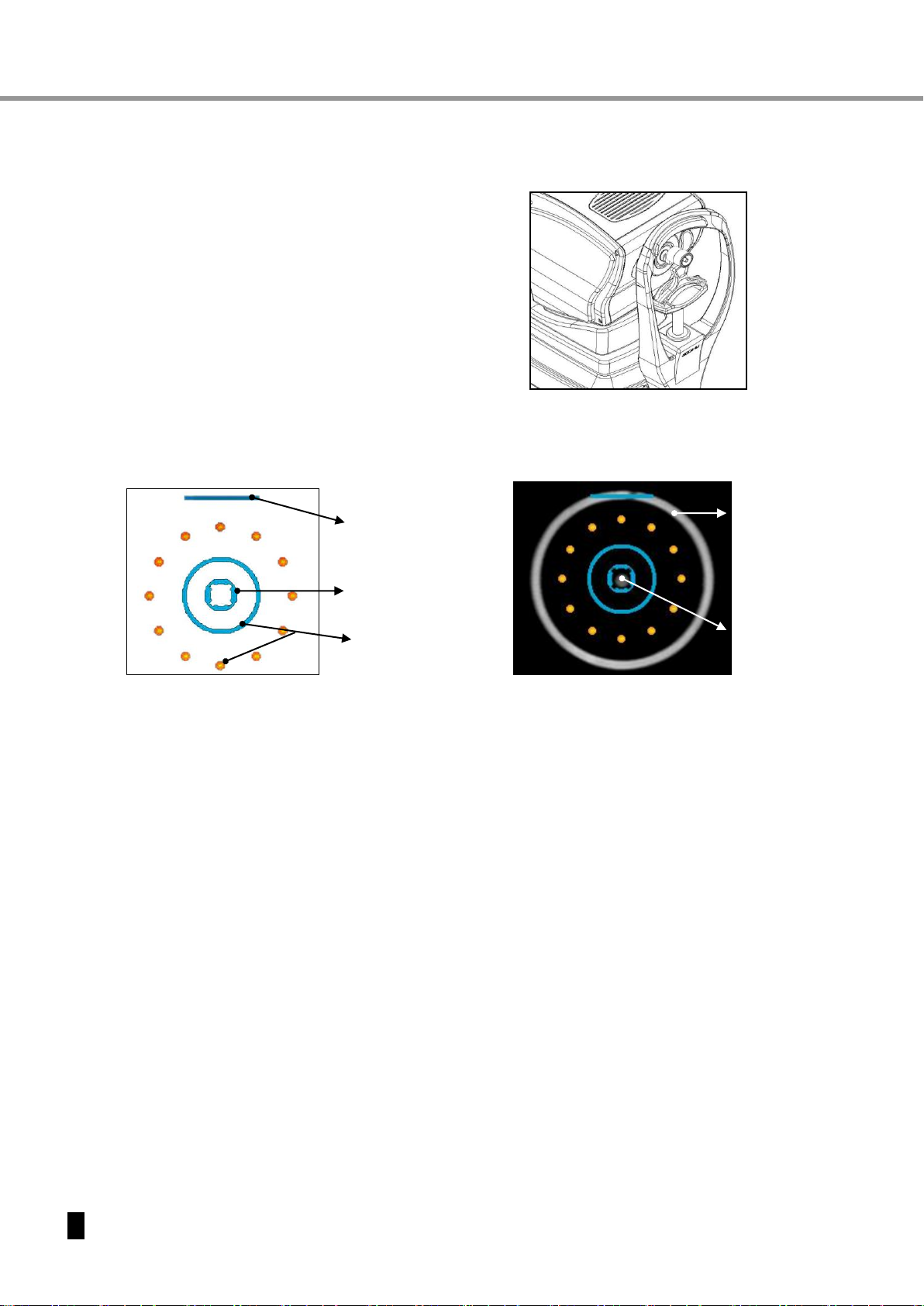
[ Drawing 6 ] model eye
6.5 Adjust the position and focus on the model eye.
Look at the monitor and move the joystick in a way that you get an image of the model eye.
Move towards or away from the model eye until a bright dot appears near the center. Focus on
the model eye by moving the joystick forward and backward so that the KERATO RING image is
displayed clearly on the monitor. As soon as the model eye is adjusted the bar appears above
the inner alignment mark.
6.6 Measurement
6.6.1 Manual measurement
a..MANU is shown in the top left corner to indicate the manual mode.
b. Press the measurement button on top of the joystick. If the measurement has failed the
message RETRY appears on the screen. In this case repeat the procedure.
c. Check whether the measured diopter value corresponds to the specification of
the model eye. The diopter value is shown in the bottom area of the model eye.
6.6.2 Automatic measurement
a. Press the [AUTO] button.
b. The MANU icon in the top left corner of the screen is switched toAUTO.
c. Automatic shooting begins when the eye is well focused.
Internal ring
mark
Outside ring
mark
Bar shows up when
well focused
Bright Dot
(Center of pupil)
KERATO RING
[ Drawing 7 ] Ring mark

19
R
Re
ef
fr
ra
ac
ct
to
om
me
et
te
er
r/
/K
Ke
er
ra
at
to
om
me
et
te
er
r
E
ER
RK
K
7
78
80
00
0
6.7 Printout
Press the print button on the moving stage to start a printout.
If the data preview is set to ON (see section 8.2.2), the results are displayed first. Press the print
button a second time to start the printout.
<PRINT TYPE-IMG >
<PRINT TYPE-ALL>
MARK Description
Average of measurement results
#Unreliable result, re-measuring
reccomanded
[I] Measurement result by IOL
mode
OUT measurement range
AVE
Out of URK-800
On auto cutting mode, don’t pull the paper before it cuts. It may cause
paper jam.
NOTE
After printing, former measurement results will be cleared automatically
when staring next measurement.
Records on thermal paper can be spoiled by heat.
If the results are to be kept for a long period, please make a copy.
[ Drawing 8 ] Printout

20
O
Op
pe
er
ra
at
ti
io
on
n
M
Ma
an
nu
ua
al
l
7. Measurement Functions
The system main functions comprise refractometry (REF), keratometry (KER), refracto/keratometry
(RK), and contact lens base curvature (CLBC) measuring. Additional features are measuring of the
corneal radius and observing the cornea.
7.1 Measurement process
7.1.1 Mode selection
a. Keep pressing the [MODE] button until the desired mode (REF, KER, RK, CLBC) shows up.
b. Press [IOL] button when measuring a patient with who has an IOL. Icon IOL shows up.
7.1.2 Regulating eye level of patient
a. Have the patient sit down and chin and forehead leaned against chin and forehead rest.
b. Line up patient’s eyes to the height aligning mark (see section 4.2) by regulating the height
of the chin rest.
7.1.3 Focusing
a. Move the stage to the left side and focus on the right eye of the patient.
b. Guide the patient to look relaxed at the red-colored part in the center of target balloon.
c. Patients are requested to open up the eye till KERATO ring images are clear.
d. Use the joystick to move the bright dot in the center of the pupil into the inner ring mark.
e. Move the joystick forward and backward to focus and to get a clear KERATO ring image.
7.1.4 Manual Measurement
a. Press the measurement button in manual mode.
b. The measurement result shows up on the screen.
The indicated result may vary depending on VD, CYL, KERATO settings.
7.1.5 Continuous Measurement
a. Perform consecutive mesurements as desired.
b. Latest data shows up after each shot.
c. Press [DISPLAY]->[CLEAR] button to clear previous data.
7.1.6 Measure other eye
a. Push joystick to the other side of the stage.
b. Icon colors of right and left eye are switched accordingly. A bar below the outside ring marks
indicate that the right eye is measured and disappears when measuring the left eye.
c. PD value shows up on the screen after the measurement.
7.1.7 Printing
a. Press [PRINT] button and print.
b. Printed contents vary depending on the user settings.
7.1.8 Automatic measuring
a. Press [AUTO] button. MANU icon changes to AUTO and the number of automatic shots is
shown.
b. Follow steps 7.1.2 and 7.1.3. The measurement starts automatically when in good focus.
The remaining measurements are indicated below the AUTO icon.
Do not place hand or fingers under the chin rest. This could result in
damage or injury.
Pull the refractometer away from the patient when moving right or left,
otherwise the face could be injured.
Keep the objective glass on the examinee side clean.
If it is smudged, it may cause inaccurate measurements.
Table of contents


