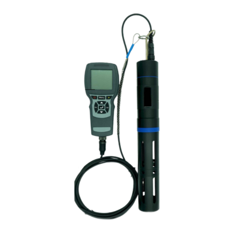
PPS 27 II User manual


Table of Contents
1. Introduction.............................................................................. 4
1.1. Overview of the PPS27 system................................................. 4
1.2. Operating modes....................................................................... 5
1.3. SRO usage................................................................................ 5
1.4. MRO usage................................................................................ 5
1.5. SRO/MRO usage....................................................................... 6
2. Setting up the PPS27 system................................................. 7
2.1. Connecting to the computer ...................................................... 7
2.2. Installing PPS SRO Software.................................................... 7
2.3. Starting the PPS SRO software................................................. 8
2.4. Surface box set up..................................................................... 8
3. Overview of PPS SRO Software............................................. 9
3.1. Main window.............................................................................. 9
4. Menu ....................................................................................... 10
4.1. File menu................................................................................. 10
4.2. Settings menu.......................................................................... 11
4.3. Logging menu.......................................................................... 15
4.4. Graph....................................................................................... 16
4.5. Program................................................................................... 16
4.6. Download................................................................................. 18
4.7. Help ......................................................................................... 18
5. Toolbar.................................................................................... 19
6. Current Readings .................................................................. 21
7. Graph ...................................................................................... 22
8. Data Table............................................................................... 23
9. Status Bar............................................................................... 24
Appendix A. Changes between PPS27 and PPS27 II............ 25
A.1. Hardware changes .................................................................. 25
A.2. Software changes.................................................................... 25

PPS 27 v6.1
4
1.Introduction
Congratulations on the purchase of the PPS27 Surface Readout
System! This manual will help you to ensure the proper use of your
system.
Pioneer Petrotech Services Inc. offers a wide range of oilfield related
instruments. These include memory and surface readout electronic
pressure recorders, surface pressure loggers, permanent installation
systems, and DPT (down hole pressure tools), all of which have
been designed and manufactured to obtain the highest accuracy and
resolution in the industry.
Pioneer Petrotech Services Inc. offers products that are durable and
reliable yet simple to operate. The lightweight design makes
transportation to and from test sites effortless. PPS has taken the
data quality obtained from quartz and sapphire transducers to new
frontiers. In addition to the transducers, the state of the art
electronics and surface mount technology have enabled PPS to
provide customers with top of the line quality pressure gauges and
loggers.
1.1. Overview of the PPS27 system
The PPS27 system consists of the surface box, one or two SRO
regular or quartz gauges and a computer with Windows
95/98/Me/2000/XP/Vista/7 operating system software installed.
The surface box and the gauge(s) are supplied by PPS. The
computer can be of any make; however, we suggest that a 486 or
better is used to accelerate operations.
The purpose of the surface box is two-fold. It communicates with the
downhole gauge(s) and stores data samples in its memory. It also
works as an interface to the computer allowing real-time data
logging, downloading of jobs stored in the box’s memory and
programming sampling rates and durations.
An operator communicates with the surface box using the software
supplied by PPS.

PPS 27 v6.1
5
1.2. Operating modes
The surface box can work in 2 modes:
1) Logging mode. This is the default mode after powering up
the surface box. The system also switches to logging mode
when logging data to a file (using the PPS SRO software)
and when the surface box is not communicating with the
computer. While in logging mode, the surface box displays
current pressure and temperature on the LCD panel (if
equipped).
2) Download mode. This mode is used while performing
certain operations when the surface box is communicating
with computer (using the PPS SRO software), including
downloading jobs, programming the box, changing the box
settings, etc. While in download mode, the surface box
displays ‘DOWNLOAD MODE’ text on the LCD panel (if
equipped).
1.3. SRO usage
SRO (Surface ReadOut) is one of the usage modes of the PPS27
system. SRO is used for the real-time data logging. In this scenario,
the surface box is connected to a computer running the PPS SRO
software. The samples are sent to the computer and stored in a data
file.
1.4. MRO usage
The PPS27 is also capable of operating in MRO (Memory ReadOut)
mode (if equipped with memory to store samples). In this scenario,
the surface box is connected to the computer and a sampling
program is entered using the PPS SRO software (see Program for
more details).
The surface box is then disconnected from the computer. It collects
data samples and stores them in the built-in memory.

PPS 27 v6.1
6
Afterwards, the computer is connected to the surface box again and
the data are downloaded into a data file for further processing (see
Download for more details).
1.5. SRO/MRO usage
Even when the box is equipped with memory, it still provides the
SRO functionality.
Whenever the box is in logging mode, it sends new data to the
computer (which can log them into the file or just update current
readings). At the same time, the box is writing samples into its job
memory for later retrieval.
When the box is in download mode, it doesn’t send new samples to
the computer nor writes them into the job memory.
Furthermore, each change from download mode to logging mode
begins a new job.

PPS 27 v6.1
7
2.Setting up the PPS27 system
Most of the surface box connections are set up by PPS personnel
while installing the surface readout system. The only connection
which can be setup by you is the connection between the surface
box and a computer (using a USB or serial communication cable).
2.1. Connecting to the computer
To establish communication with the surface box using a computer,
connect the interface box to the serial port (RS232) on the computer
using a serial cable, or to the USB port using a USB cable.
Once the surface box connection is properly set up, you can launch
the PPS SRO software.
2.2. Installing PPS SRO Software
Files needed to install the PPS27 SRO software are supplied on one
CD-ROM. As an alternative, registered customers can download the
latest version from our web site at www.pioneerps.com.
2.2.1. To install the PPS SRO software from CD-ROM:
1) Insert the CD-ROM into your CD drive.
2) View the CD contents by clicking the My Computer icon on
your computer’s desktop, and then clicking the icon for
Compact Disc.
3) Launch the installation routine by double clicking the
SETUP.EXE icon.
4) Follow the instructions as they appear during the installation
process.
If an older version of the software is already installed, it will
be automatically replaced by the new installation.

PPS 27 v6.1
8
2.2.2. To install the PPS SRO software from the website:
1) Go to our web site (www.pioneerps.com) and select the
Support menu, then the Downloads item.
2) Use the user name and password provided by Pioneer
Petrotech Services to access the list of downloadable files. If
you don’t have a user name and password, fill in the
registration form and we will generate and send you one.
3) Download the file you need and uncompress it to your hard
drive.
4) Launch the installation routine by double clicking the
SETUP.EXE icon.
5) Follow the instructions as they appear during the installation
process.
Our support site also offers the latest manuals.
2.3. Starting the PPS SRO software
You can run the PPS SRO software with or without the surface box
connected to the computer.
Click the Start button at the lower left corner of your Windows
desktop to display the Start menu. Select the PPS SRO shortcut
from the Pioneer Petrotech Services program group. The PPS SRO
software will now try to detect the connected surface box. Depending
on the result, the status bar will display the communication status (in
the right panel).
2.4. Surface box set up
The surface box has its own clock which needs to be set up prior to
any operation. To change it, see Realtime Clock.
To get the proper readings, the correct calibration file has to be in the
box’s memory. This is usually done by PPS personnel prior to the
installation, but you can change the calibration file yourself. See
Inject Calibration File (DAT) for more information.

PPS 27 v6.1
9
3.Overview of PPS SRO Software
3.1. Main window
The PPS SRO software gives you various means of interfacing with
your surface box. The PPS SRO software consists of a single main
window. The next figure shows an example of the main window while
the logging is in progress.
The main windows consists of six areas: Menu, Toolbar, Current
Readings panel, Graph, Data table and Status bar (if there are 2
gauges connected to the surface box, the Current Readings, Graph
and Data table for the individual gauges can be switched by
selecting the tab named Gauge1 or Gauge 2, respectively). These
areas are described in detail in chapters 4 to 9.

PPS 27 v6.1
10
4.Menu
The PPS SRO functionality can be accessed through the menu
system.
Items are organized into the following menus:
4.1. File menu
4.1.1. Read Data
This item allows you to read a previously saved data file and load the
values into the table and graph.
4.1.2. Inject Calibration File (DAT)
After you change the gauge connected to the surface box, you can
use this item to inject the new gauge’s calibration (DAT) file into the
surface box’s memory. This operation is essential to get the correct
pressure and temperature values for that gauge
4.1.3. Clear Memory
This item will clear the surface box’s job memory. Since this
operation is irreversible, ensure all jobs have been downloaded first.
You will be asked to confirm before the software will proceed with
clearing the memory.
4.1.4. Print Report
This item will bring up a print selection dialog offering to print (or
save as PDF file) the graph and data table.
Note: For advanced data processing and reporting
functionality, open your .REC file in the PPS SmartView
application. This application be downloaded from the PPS
web site at www.pioneerps.com.

PPS 27 v6.1
11
4.1.5. Exit
This item will close the PPS SRO application. If data logging is in
progress, a warning will be displayed asking you to stop logging first.
4.2. Settings menu
4.2.1. Data Units
This item allows you to change the pressure and temperature units
for the displayed data. Since the PPS SRO software remembers this
setting, you need to change the units only once after the installation.
The Metric button will reset to metric units (kPa for pressure and
DegC for temperature). The Imperial button will reset to imperial
units (Psi for pressure and DegF for temperature).
4.2.2. Display Time
This item allows you to change the time mode displayed in the data
table and graph. You can choose between displaying Elapsed Time
(relative) and Real Time (absolute) time. For the real-time, you can
select date and time formats.

PPS 27 v6.1
12
4.2.3. Logging Sample Rate
This item allows you to change the logging sampling rate. The
minimum sampling rate is 5 seconds, so any rate smaller than this
value will be ignored.
4.2.4. Surface box
This submenu contains the settings related to the surface box.
4.2.5. Real time Clock
This item allows you to change the real time clock used by the
surface box’s display. You can click the Current time button to get
the clock setting from the computer. When you close the dialog by
clicking the OK button, the application will store the new real time
clock setting into the surface box.
4.2.6. Panel Display Units
This item allows you to change the units on the surface box’s
display. The functionality is similar to the previous menu item (Data
Units). Since the surface box needs to be in Download mode to
change this setting, you will not be able to see the change
immediately. The new units will be displayed when the box is
switched to logging mode (when starting logging or after exiting the
application).

PPS 27 v6.1
13
4.2.7. Configuration
You can use this item to change the surface box configuration. Since
setting the wrong configuration can result in the surface box
malfunction, you will be asked to confirm before displaying the
Configuration dialog and again before writing any changes into the
surface box’s memory.
•LCD Display: Specifies whether the surface box includes an
LCD display.
•Onboard Memory: Specifies whether the surface box
includes an onboard memory for logging jobs.
•Multi-gauge: Specifies whether the surface box has more
than once SRO gauge connected.
•Gauge Type: Selection to state whether the gauges have
Quartz transducers. Quartz gauges require different
calibration information than other gauges, so this option is
important when dealing with Quartz gauges.

PPS 27 v6.1
14
•Cell phone modem: Specifies whether the surface box has
cell phone modem connected.
4.2.8. Tool Info
This item will display the information about the gauge(s) connected
to the surface box. Most of the information fields are read-only,
except the User Notes field. To see the information for a second
gauge, switch to the Gauge 2 data tab and select Tool Info again.
4.2.9. Connect to Box
In case the communication with the surface box is broken, or the
surface box wasn’t connected to the computer when starting the PPS
SRO application, you can use this item to reconnect to the box
without the need to restart the application.
The successful or failed reconnection will be indicated with a
message box. The result will also appear in the status bar.

PPS 27 v6.1
15
4.3. Logging menu
This menu contains items allowing you to start, pause and stop
logging real-time data from the surface box. It also allows you the
clear the data table and graph.
4.3.1. Start
This item will start logging data. Before logging you will be asked to
select the file where the data will be stored. You can start storing
data into a new file or you can append data into an existing file.
Note: If the box is equipped with memory, it writes data into
its own memory at the same time the data samples are
logged on the computer. Since the box has its own clock,
there is a chance the time values will be out of sync by a
couple of seconds. This is normal and is not an indication of
malfunction (it simply represents a slight difference between
the computer time and the time on the surface box).
4.3.2. Pause
If the logging is in progress, you can use this item to pause it
temporarily. To resume logging, click Start again.
4.3.3. Stop
This item will stop the logging.
4.3.4. Clear History
This item will clear the data table and graph. This cannot be done
while logging.

PPS 27 v6.1
16
4.4. Graph
Graph menu contains the items used to navigate through the data
graph.
4.4.1. Page Size
This item allows you to define the maximum number of points the
graph will display on one screen (page).
4.4.2. View Next Page*
4.4.3. View Previous Page*
4.4.4. View First Page*
4.4.5. View Last Page*
* These items allow you to navigate through graph. The current
graph position is displayed in the middle of the status bar. Also,
depending on the position, some navigation items may be disabled
(ie. you cannot move to the next page if you are on the last page).
4.5. Program
This menu contains functionality related to sampling programming.
The surface box works as a standalone memory logger, without
being connected to the computer (if equipped with built-in memory).
Sampling programming allows you to define individual sampling
steps. ie shorter sampling rate for the first hour, medium sampling
rate for the next few hours and than longer sampling rate until the
memory fills up.

PPS 27 v6.1
17
4.5.1. View Existing
This item will read the existing program from the surface box and
display the Sampling Program dialog.
The sampling program consists of up to 15 individual steps. Each
step is defined by rate and duration. After the last step has finished,
the surface box will continue taking data samples with the rate of the
last program step.
The Read Program button will read the sampling program from the
surface box. The Clear button will clear the program steps table. The
Write Program button will store the sampling program into the
surface box.
4.5.2. Create New
This item has the same functionality as the previous item, except the
Sampling Program dialog is started without reading the program from
the surface box. See View Existing for more details.

PPS 27 v6.1
18
4.6. Download
This menu consists of one item only and allows you to download jobs
stored in the surface box’s memory. After clicking the Download
menu, the list of the jobs is displayed.
You can select any job and click the OK button to launch the file
saving dialog. The PPS SRO application will offer you a default file
name for the job to be downloaded into. If you wish, you can change
this name.
If you select and existing file, the downloaded job will be appended
to it. This option could be used for regular (ie. weekly) downloads to
keep one continuous file, since each download requires switching
the box into download mode (which in turn creates a new job in the
box’s memory).
While the job is being downloaded, a progress window displays the
approximate time remaining.
Afterwards, a message will appear, informing you the download is
complete.
4.7. Help
This menu item will launch the PPS SRO help system.

PPS 27 v6.1
19
5.Toolbar
Some frequently used menu items can be also accessed using the
toolbar buttons.
The Start, Pause and Stop buttons have the same functionality as
the same-named items from the Logging menu. See Logging menu
for more details.
The Key Locking button allows you to lock the menu items and
toolbar buttons to prevent either starting or stopping logging. When
locking, the password dialog will ask you to enter the password used
for unlocking. You will have to enter this password to unlock the
menu items and toolbar buttons.
The Graph navigation buttons allow you to display the previous or
next page of the graph. See Graph for more details.
Table of contents
Other PPS Measuring Instrument manuals
Popular Measuring Instrument manuals by other brands
Michell Instruments
Michell Instruments XTC601 user manual

DynAmp
DynAmp LKAT2 Installation, operation and service instructions
Krohn-Hite
Krohn-Hite 6900B Operating and maintenance manual
MARTINDALE
MARTINDALE VR2250 User instruction manual
SMC Networks
SMC Networks PSE201-A4C Operation manual
VEE GEE
VEE GEE BX-2 Operation manual


