ELICA KIT0179547 Installation guide

1
Use, Care, and
Installation Guide
Guide
d’utilisation,
d’entretien et
d’installation
Guía de
instalación, uso y
mantenimiento
READ AND SAVE THESE
INSTRUCTIONS
LISEZ CES
INSTRUCTIONS ET
CONSERVEZ-LES
LEA Y CONSERVE
ESTAS INSTRUCCIONES
LIB0180581
Printed in Mexico
Models: KIT0179547

2
English
APPROVED FOR RESIDENTIAL APPLIANCES
FOR RESIDENTIAL USE ONLY
READ AND SAVE THESE INSTRUCTIONS
PLEASE READ ENTIRE INSTRUCTIONS BEFORE PROCEEDING.
INSTALLATION MUST COMPLY WITH ALL LOCAL CODES.
IMPORTANT: Save these Instructions for the Local Electrical Inspector’s use.
INSTALLER: Please leave these Instructions with this unit for the owner.
OWNER: Please retain these instructions for future reference.
Safety Warning: Turn o power circuit at service panel and lock out panel, before wiring this appliance.
Requirement: 120 V AC, 60 Hz. 15 or 20 A Branch Circuit.
Important Safety Notice 3
Installation requirements 4
Electrical Requirements 4
Tools and Parts 5
Product dimensions 6
Venting Requirements 6
Installation Instructions 7
Prepare location 7
Install Blower System 12
Electrical connection instructions 13
Electrical Connection for External Blower Motor System 13
Electrical Connection Inside Range Hood Between External Blower System and Range Hood 14
Warranty 15

3
Important Safety Notice
I CAUTION
FOR GENERAL VENTILATING USE ONLY. DO NOT USE TO
EXHAUST HAZARDOUS OR EXPLOSIVE MATERIALS OR
VAPOURS.
IWARNING
TO REDUCE THE RISK OF FIRE, ELECTRIC SHOCK, OR
INJURY TO PERSONS, OBSERVE THE FOLLOWING:
A. Use this unit only in the manner intended by the manufac-
turer. If you have questions, contact the manufacturer.
B. Before servicing or cleaning the unit, switch power o at
service panel and lock service panel disconnecting means to
prevent power from being switched on accidentally.
When the service disconnecting means cannot be locked,
securely fasten a prominent warning device, such as a tag,
to the service panel.
C. Installation work and electrical wiring must be done by
qualified person(s) in accordance with all applicable codes
& standards, including fire-rated construction.
D. Sucient air is needed for proper combustion and
exhausting of gases through the flue (Chimney) of fuel
burning equipment to prevent back- drafting.
Follow the heating equipment manufacturers guideline and
safety standards such as those published by the national
fire protection association (NFPA), the american society
for heating, refrigeration and air conditioning engineers
(ASHRAE), and the local code authorities.
E. When cutting or drilling into wall or ceiling, do not damage
electrical wiring and other hidden utilities.
F. Ducted systems must always be vented to the outdoors.
I CAUTION
To reduce risk of fire and to properly exhaust air, be sure to
duct air outside - do not vent exhaust air into spaces within
walls, ceilings, attics, crawl spaces, or garages.
IWARNING
TO REDUCE THE RISK OF FIRE, USE ONLY METAL DUCT
WORK.
Install this hood in accordance with all requirements specified.
IWARNING
To reduce the risk of fire or electric shock, do not use this
hood with any external solid state speed control device.
IWARNING
TO REDUCE THE RISK OF A RANGE TOP GREASE FIRE.
a)Never leave surface units unattended at high settings.
Boilovers cause smoking and greasy spillovers that may
ignite. Heat oils slowly on low or medium settings.
b) Always turn hood ON when cooking at high heat or when
flambeing food (I.e. Crepes Suzette, Cherries Jubilee,
Peppercorn Beef Flambe’).
c)Clean ventilating fans frequently. Grease should not be
allowed to accumulate on fan or filter.
d) Use proper pan size. Always use cookware appropriate for
the size of the surface element.
IWARNING
TO REDUCE THE RISK OF INJURY TO PERSONS, IN THE
EVENT OF A RANGE TOP GREASE FIRE, OBSERVE THE
FOLLOWING:a
a)SMOTHER FLAMES with a close-fitting lid, cookie sheet, or
other metal tray, then turn o the gas burner or the electric
element. BE CAREFUL TO PREVENT BURNS. If the flames
do not go out immediately, EVACUATE AND CALL THE
FIRE DEPARTMENT.
b) NEVER PICK UP A FLAMING PAN - you may be burned.
c)DO NOT USE WATER, including wet dishcloths or towels - a
violent steam explosion will result.
d) Use an extinguisher ONLY if:
5) You know you have a class ABC extinguisher, and you
already know how to operate it.
6) The fire is small and contained in the area where it
started.
7)The fire department is being called.
8) You can fight the fire with your back to an exit.
i) Ducted fans must always be vented to the outdoor.
aBased on “Kitchen Fire Safety Tips” published by NFPA.
I CAUTION
Automatically Operated Device - To reduce the risk of
Injury disconnect from power supply before servicing.
For double Blower Motor Models (ELN136S2, ELN142S2, ELN148SS, ELI136S2, ELI142S2, EAR134S4, EAR140S4, EAR146S4,
ECL136S4, ECL142S4, ECL148S4, ETR134S1, ETR146SS)

4
Installation requirements
Electrical Requirements
IMPORTANT
Observe all governing codes and ordinances.
It is the customer’s responsibility:
• Have a qualified technician install the in-line blower motor
system.
• All openings in the ceiling and wall where the in-line blower
motor system will be installed must be sealed.
• Ensure that the electrical installation is adequate and in
conformance with National Electrical Code, ANSI/NFPA
70 (latest edition), or CSA Standards C22.1-94, Canadian
Electrical Code, Part 1 and C22.2 No. 0-M91 (latest edition)
and all local codes and ordinances.
• If codes permit and a separate ground wire is used, it is
recommended that a qualified electrician determine that
the ground path is adequate.
• A copy of the above code standards can be obtained from:
National Fire Protection Association
One Batterymarch Park
Quincy, MA 02269
CSA International
8501 East Pleasant Valley Road
Cleveland, OH 44131-5575
• A 120 volt, 60 Hz., AC only, 15-amp, fused electrical circuit
is required.
• If the house has aluminum wiring, follow the procedure
below:
1 Connect a section of solid copper wire to the pigtail leads.
2 Connect the aluminum wiring to the added section
of copper wire using special connectors and/or tools
designed and UL listed for joining copper to aluminum.
Follow the electrical connector manufacturer’s
recommended procedure. Aluminum/copper connection
must conform with local codes and industry accepted.
wiring practices.
• Save Installation Instructions for electrical inspector’s use.
• Wire sizes and connections must conform with the rating
of the appliance as specified on the model/serial rating
plate. The model/serial plate is located behind the kit on
the rear wall.
• Wire sizes must conform to the requirements of the
National Electrical Code, ANSI/NFPA 70 (latest edition), or
CSA Standards C22. 1-94, Canadian Electrical Code, Part 1
and C22.2 No. 0-M91 (latest edition) and all local codes and
ordinances.
For Mobile Home Installations
The installation of this external blower motor system must
conform to the Manufactured Home Construction Safety
Standards, Title 24 CFR, Part 328 (formerly the Federal
Standard for Mobile Home Construction and Safety, Title
24, HUD, Part 280) or when such standard is not applicable,
the standard for Manufactured Home Installation 1982
(Manufactured Home Sites, Communities and Setups) ANSI
A225.1/NFPA 501A*, or latest edition, or with local codes.

5
Tools and Parts
Gather the required tools and parts before starting
installation. Read and follow the instructions provided with
any tools listed here.
Tools needed
• Drill
• 1¼” (3 cm) drill bit
• ⁄” (0.5 cm) drill bit
• Pencil
• Wire stripper or utility knife
• Tape measure or ruler
• Pliers
• Caulking gun and weatherproof caulking compound
• Vent clamps
• Jigsaw or keyhole saw
• Metal snips
• Screwdrivers
•Phillips
•Flat-blade
Parts not supplied
• 6 AWG wires, one each of the following colors: black, white,
red, blue, gray, and green or green/yellow (ground)
NOTE: The length of the conduit and AWG wires is
determined by the distance between the in-line blower
motor and range hood terminal boxes.
• 11 - UL listed wire connectors
Parts supplied
Remove parts from packages. Check that all parts are
included.
• Shell for blower motor assembly
• Hardware bag with:
Supplied Part Pieces Supplied Part Pieces
Strain relief connector
2
Ø 12 mm strain relief
1
4.2x8 mm screws 10
6x13.5 mm
2
6-wire blower connector
1
Torx adapter
T10 1
T20 1
6.4x18 mm at washers
4
4.2 x 15 screws
10
6 x 16 mm screws
4Strap 2.5x95 mm 3
Spring tab
1
Neoprene washers
20
6.3x60 mm screws
7
10x50 mm wall anchors
7
Support bracket
1
Clip nuts
4

6
Product dimensions
D
C
B
A
E
C
Dimensions
A21 15⁄16” (55.56 cm)
B20 11⁄16” (52.56 cm)
C7 7⁄8” (20 cm)
D24 7⁄16” (61.95 cm)
E22 10⁄16” (57.38cm)
NOTE: The minimun installation height recommended for
the external blower kit is 40” (102 cm) from the floor to the
center of the round vent system.
Venting Requirements
• The vent system must terminate to the outdoors.
• Do not terminate the vent system in an attic or other
enclosed area.
• Do not use 4” (10.2 cm) laundry-type vent or wall caps.
• Use round, metal vent only. Rigid metal vent is
recommended. Plastic or metal foil vent is not
recommended.
• The length of the vent system and number of elbows
should be kept to a minimum to provide ecient
performance.
For the most efficient and quiet operation:
• Use no more than three 90° elbows.
• Make sure there is a minimum of 24” (61.0 cm) of straight
vent between the elbows if more than 1 elbow is used.
• Do not install 2 elbows together.
• Use clamps to seal all joints in the vent system.
• The vent system must have a damper.
• Use weatherproof caulking to seal the exterior wall or roof
opening around the cap.
• The size of the vent should be uniform.
Cold weather installations
An additional backdraft damper should be installed to
minimize backward cold air flow. A thermal break should be
installed to minimize conduction of outside temperatures as
part of the vent system. The damper should be on the cold air
side of the thermal break.
The thermal break should be as close as possible to where the
vent system enters the heated portion of the house.
Typical External Blower System Installations
A 8” (20.32 cm) - 10” (25.4 cm) round vent system is needed
for installation (not included). The external blower system
inlet and outlet openings are 8” (20.32 cm) - 10” (25.4 cm)
round. The exhaust (outlet) opening on the range hood must
also at leat 8” (25.4 cm) round.
NOTE: Flexible vent is not recommended. Flexible vent
creates back pressure and air turbulence that greatly reduce
performance.
The vent system can terminate either through the wall.
NOTE: Plywood may be used as a mounting base to span
open areas between ceiling joists and rafters. If used, be
sure to use plywood capable of supporting the weight of the
external blower system (83 lb [37.5 kg]).
A.
BC
B
A
A. Range Hood
B. Vent Duct
C. External Blower Kit

7
Installation Instructions
Prepare location
• Before making cutouts, make sure there is proper clearance
within the ceiling or wall for the exhaust vent.
• When cutting or drilling into the ceiling or wall, do not
damage electrical wiring or other hidden utilities.
• Check that all installation parts have been removed from
the shipping carton.
NOTE: For the correct performance of your In-Line Blower
System you must remove the Range Hood Internal Motor
Blower.
Remove Range Hood Internal Motor Blower
1 Remove grease filters from range hood.
2 Disconnect the blower power cord from de wire box.
B
A
A. Wire box connector
B. Power cord
3 For EAR134S4, EAR140S4, EAR146S4, ECL136S4,
ECL142S4, ECL148S4, ETR134S1 and ETR146SS range
hood models you have to remove the 4 - 6 x 16 mm screws
holding the blower motor.
4 For ELN136S2, ELN142S2, ELN148SS, ELI136S2 and
ELI142S2 models remove duct covers and the 4 - 6 x 16
mm blower motor screws
5 Remove the motor mounting plate by setting free the
spring clip.
NOTE: The spring clip should be outside the slot in the
mounting plate.
A. Mounting plate
B. Spring Clip
A
B
A. Mounting plate
B. Spring Clip
A
B

8
6 Slide out the left mounting plate from under the motor
mounting bracket.
A
B
A. Motor mounting plate
B. Motor mounting bracket
A
B
A. Motor mounting plate
B. Motor mounting bracket
7 Remove the range hood internal blower motor.
8 Replace the grease filters on the hood.
Prepare for Mounting the External Blower System
The External Blower System must be fastened to a secure
structure of the wall or new or existing frame construction.
The 7 holes on either the inlet (bottom) side or the outlet
(top) side of the blower must be used to mount the external
blower system to the structure.
NOTE: The mounting hole locations must span the studs.
Additional stud framing may be required. Plywood may be
used to span open areas between ceiling joists or roof rafters
to aid installation. This structure must be strong enough to
support the weight of the external blower system (83 lb [37.5
kg] min).
Prepare the External Blower System
IWARNING
Excessive Weight Hazard
Use two or more people to move and install range hood.
Failure to do so can result in back or other injury.
1 Disconnect power.
2 Using two or more people, move the external blower motor
system to the mounting location.
3 Remove the 20 screws from the front cover of the external
blower motor housing and set them aside.
4 Remove the front cover of the external blower motor
housing and set it aside.
NOTE: To make the external blower motor housing easier
to mount, the blower motor assembly can be removed.
5 Disconnect the motor electrical plug from the blower
motor assembly.
6 Remove the screws that secure the blower motor assembly
to the external blower housing and set them aside.
7 Pull the spring clip to release the blower motor assembly.
Remove the blower motor assembly from the housing and
place it on a covered surface.
A. Front cover
B. Blower mounting screws
C. Motor electrical plug
B
C
A
Prepare the External Blower System
IWARNING
Excessive Weight Hazard
Use two or more people to move and install range hood.
Failure to do so can result in back or other injury.
1 Disconnect power.
2 Determine which venting method to use: roof or wall
exhaust.
3 Using two or more people, move the in-line blower motor
system to the mounting location.
4 Remove the 10 - 3.1 x 15 mm screws from the cover of the
shell and save them for later. Remove the front cover of the
shell and set it aside. A
B
A
A. 3.1 x 15 mm screws
B. Cover of the shell

9
5 Remove cover of the shell.
For models EAR134S4, EAR140S4, EAR146S4, ECL136S4,
ECL142S4, ECL148S4, ETR134S1 and ETR146SS
1 Unscrew the 4 - 4.2 x 8 mm (A) screws from the mounting
plate support and save them for later.
A
2 Fix support bracket (A) and spring tab (B), support
brackets to the appropriate screw slots following the next
image.
C
A
B
D
3 Place nuts over the top of the shell on the right slots
A
A
A. Nuts
4 Slide halfway the mounting plate of the blower motor
assembly, from the front of the shell, gently over the
mounting plate support.
A
C
B
A. Mounting plate
B. Spring tab
C. Wiring connection
5 Push the right end of the motor mounting plate up and
snap it into the spring tab.
NOTE: The spring tab should be outside the slot in the
mounting plate. Align mounting holes in motor mounting
plate with motor mounting clip nuts and install 4 - 6 x 16
mm screws with clip nuts.
A

10
A
B
C
A. Screw with lock washer
B. Mounting hole in motor mounting plate
C. Clip nut
6 Slide the mounting plate support (A) into the shell over the
side supports.
A
B
7 Replace the mounting plate support to the side supports
and fix with the previously removed 4 screws and the
additional 5 - 4.2 x 8 mm screws contained on the
hardware bag.
8 Replace the shell cover and fix with the previously removed
10 screws and the additional 5 - 4.2 x 8 mm screws
contained on the hardware bag.
9 Attach power cord connector from the range hood to
connector on wiring box.
B
A
A. Wiring box connector
B. Power supply connector from range hood
For models ELN136S2, ELN142S2, ELN148SS, ELI136S2 and
ELI142S2
1 Unscrew the 4 - 4.2 x 8 mm screws (A) from the mounting
plate support and save them for later.
A
2 Fix support bracket and spring tab, support brackets to the
appropriate screw slots following the next image.

11
3 Slide the mounting plate of the blower motor assembly,
from the front of the shell, gently over the mounting plate
support.
4 Push the right end of the motor mounting plate up and
snap it into the spring tab.
NOTE: The spring tab should be outside the slot in the
mounting plate.
5 Place nuts over the top of the shell on the right slots and
align mounting holes in motor mounting plate (A) with
motor mounting clip nuts and install 4 - 6 x 16 mm screws
with clip nuts (B).
A
B
A
B
C
A. Screw with lock washer
B. Mounting hole in motor mounting plate
C. Clip nut
6 Slide the mounting plate support (A) into the shell over the
side supports.
A
B
7 Replace the mounting plate support to the side supports
and fix with the previously removed 4 screws and the
additional 5 - 4.2 x 8 mm screws contained on the
hardware bag.
8 Attach power cord connector from the range hood to
connector on wiring box.
B
A
A. Wiring box connector
B. Power supply connector from range hood
12
Install Blower System
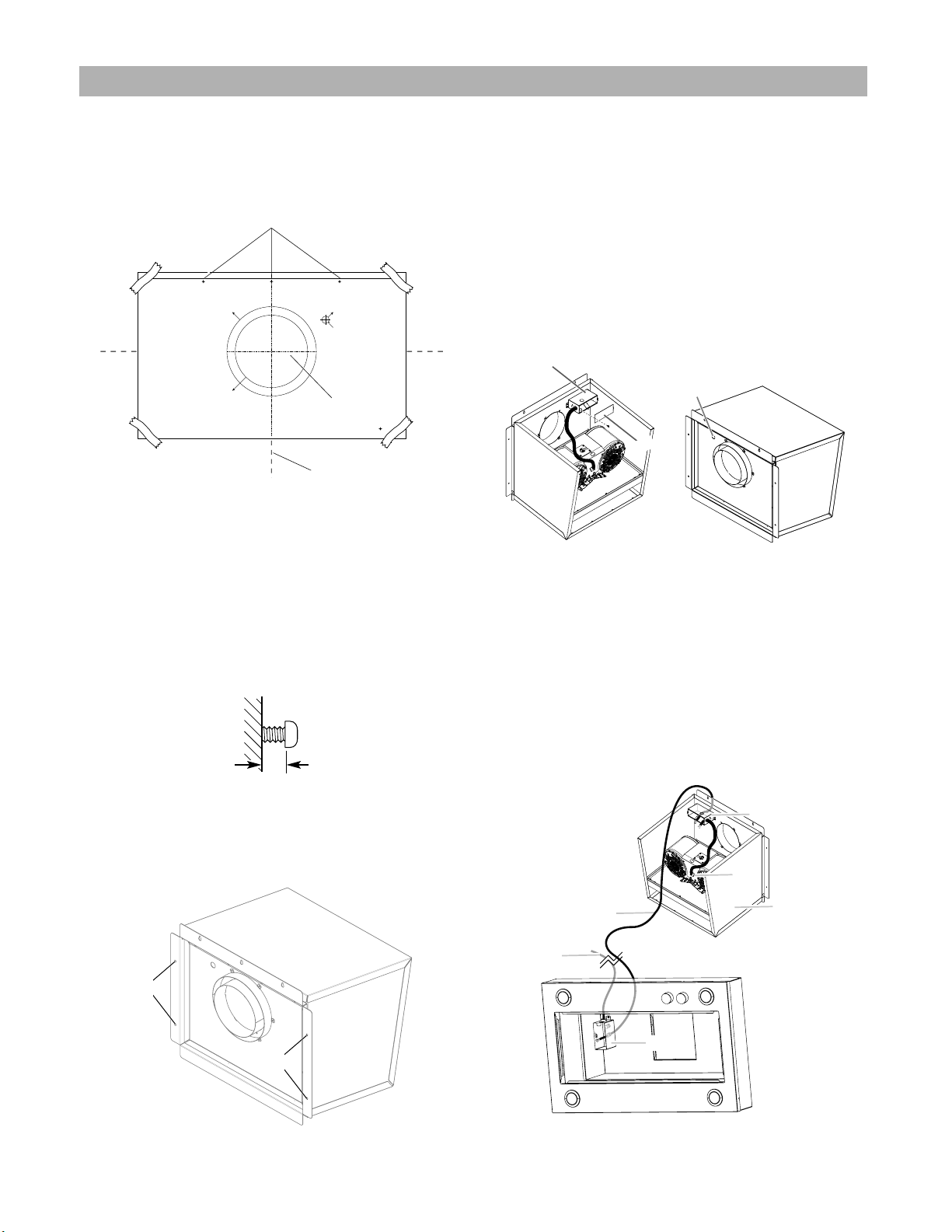
1 Determine and mark the vent system exhaust’s vertical and
horizontal centerlines on the wal where the kit is going to
be installed.
2 Disconnect the power.
3 Tape the installation template in place, aligning the
template centerlines with the wall marks already made.
Ø 13/16"
(Ø 21 mm)
WIRING HOLE
TROU DE CÂBLAGE
ORIFICIO DE CABLEADO
Ø 10 1/4"
(Ø 260 mm)
Ø 8 1/4"
(Ø 210 mm)
CENTERLINE
AXE CENTRAL
LÍNEA DE CENTRO
TOP BORDER
BORD SUPERIEUR
BORDE SUPERIOR
DIM0156915
A
A
B
A. Intallation template centerlines
B. Upper mounting holes
4 Determine and make all necessary cuts for the vent system.
IMPORTANT: When cutting or drilling into the wall, do not
damage electrical wiring or other hidden utilities.
5 Determine the location where the ⁄” (1.3 cm) wiring
conduit will be routed through the wall between the
external blower and the range hood.
6 Drill a 1⁄” (3.2 cm) hole at this location.
7 Drill the upper mounting pilot holes using a ⁄” (0.95 cm)
drill bit and place the wall anchors.
8 Fix 3 - 6.3 x 60 mm screws to the anchors leaving a ⁄”
(6.4 mm) gap between the wall and the back of the upper
screws head to slide range hood into place.
1⁄4”
(6.4 mm)
9 Remove the template.
10 Place the kit in the desired location and mark with a pencil
the location of the 4 mounting holes.
11 Remove the External Blower Kit.
12 Drill the 4 mounting pilot holes using a ⁄” (0.95 cm) drill
bit and place the wall anchors.
A
A
A. Mounting holes
13 Place and attach the external blower motor housing to the
mounting location with mounting 4 - 6.3 x 60 mm screws
and 4 - 4 x 1.8 washers. Parts are included with the range
hood motor kit.
NOTE: The blower motor housing can be mounted using
4 holes from either the inlet side or the outlet side of the
blower.
14 If removed, reinstall the blower motor assembly and secure
it with the screws previously removed.
15 If removed, reattach the motor electrical plug to the
connector on the blower motor assembly.
Complete Preparation
1 Locate the electrical terminal boxes in the external blower
housing and range hood. Remove the terminal box covers
and set the covers and screws aside.
A. Terminal Box Cover
B. Knockout
C. Terminal Box cover screw
C
B
A
2 Remove the electrical knockout from the external blower
housing and range hood (see the range hood installation
instructions) to prepare for the installation of the UL listed
or CSA approved ⁄” (1.3 cm) wiring conduit and conduit
connector.
3 With the range hood mounted (see the range hood
installation instructions), run the ⁄” (1.3 cm) wiring conduit
between the external blower motor housing and the
range hood (see the KIT0153054 electrical connection
instructions). Pull enough ⁄” wiring conduit to allow for
easy connection to the terminal boxes in the external
blower housing and range hood.
NOTE: If necessary remove the range hood transition.
B
C
A
D
E
F
A. External Blower Kit
B. Range Hood Terminal Box
C. Power Supply wiring Conduit
D. External Blower Wiring Conduit (not
included)
E. External Blower Terminal Box
F. External Motor Electrical Plug Cable

13
4 Install the conduit connectors and conduit to the external
blower housing and range hood electrical terminal boxes.
NOTE: If removed, install the range hood transition.
5 Connect the vent system to the range hood and external
blower system. Seal all joints with clamps.
6 Once the electrical connection is made, place the kit front
cover with the neoprene washers and the blower mointing
screws.
IWARNING
For the correct use of your product, you must install the
neoprene washers to avoid the water entrance.
Replace the shell cover and fix with the previously removed
10 screws and the additional 5 - 4.2 x 8 mm screws
contained on the hardware bag.
B
C
A
D
A. Blower mointing screws
B. Neoprene washers
C. Front cover
D. External Blower
Electrical connection instructions
Electrical Connection for External Blower Motor System
IWARNING
Electrical Shock Hazard
Disconnect power before servicing.
Replace all parts and panels before operating.
Failure to do so can result in death or electrical shock.
IWARNING
Electrical Shock Hazard
Electrically ground blower.
Connect ground wire to green and yellow ground wire in
terminal box.
Failure to do so can result in death or electrical shock.
NOTE: The electrical diagram is attached at the end of the
document.
Electrical Connection Inside External Blower System
1 Disconnect power.
2 Connect the wires from the wiring conduit to the wires
from the motor electrical plug cable inside the external
blower housing terminal box.
3 Use UL listed wire connectors and connect the black wires
(C) together.
4 Use UL listed wire connectors and connect the white wires
(D) together.
5 Use UL listed wire connectors and connect the red wires
(E) together.
6 Use UL listed wire connectors and connect the blue wires
(F) together.
7 Use UL listed wire connectors and connect the gray wires
(G) together.
8 Connect the green (or green/yellow) ground wire from the
wiring conduit to the green (or yellow/green), ground wire
(H) in the terminal box using UL listed wire connectors.
A. Strain relief
B. UL listed wire connectors
C. Black wires
D. White wires
E. Red wires
F. Blue wires
G.Gray wires
H. Green (or yellow/green) and green/
yellow wires
I. Motor electrical plug cable
A
B
C
D
E
F
G
H
I
9 Once the connection is done, in necessary to adjust the 6
wire connector with the included strap.
A
B
C
D
A. Ground wires connection
B. 6 wire connector
C. Strap
D. Strain relief
10 Reinstall the external blower terminal box cover and
screws.
11 Reinstall the front cover of the external blower housing and
secure it with 10 mounting screws.
14
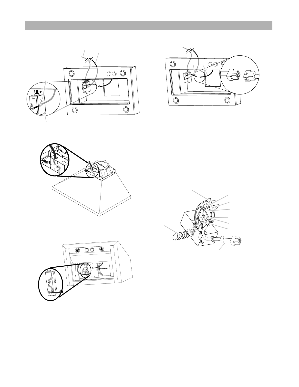
Electrical Connection Inside Range Hood Between External Blower System and Range Hood
1 With the range hood mounted (see the range hood
installation instructions), locate the wiring cable connector
inside the range hood.
C
D
A
B
MODELS ETR134S1, ETR146SS, EAR134S4, EAR140S4 and
EAR146S4
A. Range Hood Junction Box
B. Range Hood knockout for Wire Connector Assembly
C. Wire Connector Assembly (provided in the In-Line Blower Kit)
D. Power Supply Wiring Conduit
MODELS ELN136S2, ELN142S2, ELN148SS,
ELI136S2 and ELI142S2
A. Range Hood Junction Box
B. Range Hood knockout for Wire Connector Assembly
C. Wire Connector Assembly (provided in the External Blower Kit)
D. Power Supply Wiring Conduit
MODELS ECL136S4, ECL142S4 and ECL148S4
A. Range Hood Junction Box
B. Range Hood knockout for Wire Connector Assembly
C. Wire Connector Assembly (provided in the External Blower Kit)
D. Power Supply Wiring Conduit
2 Connect the 6 wire connector assembly supplied with the
in-line blower motor system to the mating connector from
the range hood.
B
A
A. Wire Connector Assembly (provided in the In-Line Blower Kit)
B. Hood Insert Blower Connector
3 Install UL listed or CSA approved strain reliefs. Run through
the strain reliefs the 6 wire connector and the In-Line
Blower wiring conduit (not incluided leaving enough wire
length to make the wiring connections.
4 Tighten the strain relief screws.
5 Connect the wires from the 6- wire connector assembly to
the wires from the wiring conduit inside the range hood
terminal box.
NOTE: Connect the green (or green/yellow) ground wire
from the wiring conduit to the green (or bare) ground wire
from the home power supply and to the and to the green/
yellow ground wire from the 6-wire connector assembly
(H) using UL listed wire connectors (see the “Make
Electrical Power Supply Connections to Range Hood”
section in the range hood installation instructions).
A
B
C
D
E
F
G
H
I
A. Strain relief
B. UL listed wire connectors
C. Black wires
D. White wires
E. Red wires
F. Blue wires
G.Gray wires
H. Green (or yellow/ green) and green / yellow wires
I. Motor electrical plug cable
6 Connect the home power supply wiring to the range hood
following the instructions that are supplied with the range
hood.
7 Reinstall the range hood terminal box cover.
8 Reconnect power.

Warranty
ELICA North America
TWO-YEAR LIMITED WARRANTY
TO OBTAIN SERVICE UNDER WARRANTY
Owner must present proof of original purchase date. Please keep a copy of your dated proof of purchase (sales slip) in
order to obtain service under warranty.
PARTS AND SERVICE WARRANTY
For the period of two (2) years from the date of the original purchase, Elica will provide free of charge, non consumable
parts or components that failed due to manufacturing defects. During these two (2) years limited warranty, Elica will also
provide free of charge, all labor and in-home service to replace any defective parts.
WHAT IS NOT COVERED
• Damage or failure to the product caused by accident or act of God, such as, flood, fire or earthquake.
• Damage or failure caused by modification of the product or use of non-genuine parts.
• Damage or failure to the product caused during delivery, handling or installation.
• Damage or failure to the product caused by operator abuse.
• Damage or failure to the product caused by dwelling fuse replacement or resetting of circuit breakers.
• Damage or failure caused by use of product in a commercial application.
• Service trips to dwelling to provide use or installation guidance.
• Light bulbs, metal or carbon filters and any other consumable part.
• Normal wear of finish.
• Wear to finish due to operator abuse, improper maintenance, use of corrosive or abrasive cleaning products/pads and
• When the product has not been operated in accordance with the accompanying instructions for use.
oven cleaner products.
WHO IS COVERED
This warranty is extended to the original purchaser for products purchased for ordinary residential use in North America
(Including the United States, Guam, Puerto Rico, US Virgin Islands & Canada).
This warranty is non-transferable and applies only to the original purchaser and does not extend to subsequent owners of
the product. This warranty is made expressly in lieu of all other warranties, expressed or implied, including, but not limited
to any implied warranty of merchantability or fitness for a particular purpose and all other obligations on the part of Elica
North America, provided, however, that if the disclaimer of implied warranties is ineective under applicable law, the dura-
tion of any implied warranty arising by operation of law shall be limited to two (2) years from the date of original purchase
at retail or such longer period as may be required by applicable law.
This warranty does not cover any special, incidental and/or consequential damages, nor loss of profits, suered by the
original purchaser, its customers and/or the users of the Products.
WHO TO CONTACT
To obtain service under warranty or for any service related question:
USA & CANADA - Western Provinces
SERVICE POWER
888 732 8018
CANADA - Ontario Province
AGI Services
888 651 2534
CANADA - Quebec & Atlantic Provinces
Ateliers G. Paquette
800 463 0119
•
•
To ensure prompt after-sales service, when you call we will kindly ask you to provide the following information indicated
on the nameplate inside the hood: hood model, 12 NC and date of purchase on original invoice.To access the nameplate,
all you have to do is remove the grease filters.
•
Register your product in
elica.com
and earn a 3rd year of factory
warranty, covering all parts
plus in-home labor.
12NC:
Hood model:
Serial No:
Date of purchase on original invoice:

16
Français
APPROUVÉ POUR LES APPAREILS DE TYPE RÉSIDENTIEL
POUR UNE UTILISATION RÉSIDENTIELLE SEULEMENT
LISEZ CES INSTRUCTIONS ET CONSERVEZ-LES
VEUILLEZ LIRE CES INSTRUCTIONS AU COMPLET AVANT DE COMMENCER.
L’INSTALLATION DE L’APPAREIL DOIT RESPECTER TOUS LES CODES EN VIGUEUR.
IMPORTANT : Conservez ces instructions afin de pouvoir les remettre à l’inspecteur-électricien de votre région.
INSTALLATEUR : Veuillez laisser ces instructions avec l’appareil pour le propriétaire.
PROPRIÉTAIRE : Veuillez conserver ces instructions pour pouvoir vous y référer plus tard.
Avertissement de sécurité : Coupez l’alimentation du circuit dans le panneau électrique et verrouillez le
panneau avant de raccorder les fils de cet appareil.
Exigence : 120 V c.a., 60 Hz circuit de dérivation de 15 V c.a., 20 Hz, de 15 ou 20 A.
Avis de Sécurité Important 17
Exigences électriques 18
Tools and Parts 19
Dimension du produit 20
Exigences concernant l’évacuation 20
Instructions d’installation 21
Préparation de l’emplacement 21
Installer le système de soufflerie 26
Instructions de connexion électrique 27
Connexion électrique pour le système de moteur soufflant externe 27
Connexion électrique à l’intérieur de la hotte entre le système de ventilation externe et la hotte 28
Garantie 29

17
Avis de Sécurité Important
I AVERTISSEMENT
POUR RÉDUIRE LES RISQUES D’INCENDIE, DE CHOC
ÉLECTRIQUE ET DE BLESSURE, RESPECTER LES DIRECTIVES
SUIVANTES:
A. Utiliser cet appareil uniquement aux fins prévues par le
fabricant. Si vous avez des questions à propos de l’appareil,
communiquez avec le fabricant.
B. Avant de faire l’entretien de l’appareil ou de le nettoyer,
coupez l’alimentation dans le panneau électrique et
verrouillez le panneau en bloquant le dispositif permettant
d’empêcher d’activer l’alimentation accidentellement. S’il
n’est pas possible de verrouiller l’accès au panneau, fixez
une étiquette très voyante au panneau électrique.
C. Une personne qualifiée doit eectuer l’installation et le
câblage des fils électriques en conformité avec tous les
codes et toutes les normes, y compris la cote de résistance
au feu.
D. Il est important de prévoir susamment d’air pour assurer
une bonne combustion de l’équipement de chaue et
l’évacuation adéquates des gaz par le conduit de cheminé
afin de prévenir les refoulements d’air. Respectez les
directives et les normes de sécurité des fabricants de
l’équipement de chauage, comme celles publiées par la
National Fire Protection Association (NFPA), la American
Society for Heating, Refrigeration and Air Conditioning
Engineers (ASHRAE) et le code des autorités de votre
région.
E. Au moment de couper ou de percer un mur ou un plafond,
assurez-vous de ne pas endommager la filerie électrique ou
tout autre accès à un service publique.
F. Il faut toujours évacuer à l’extérieur les systèmes conduit.
I ATTENTION
Pour réduire les risques d’incendie et évacuer l’air correctement,
assurez-vous que le conduit mène à l’extérieur; il ne faut pas
évacuer l’air dans l’espace entre les murs, dans les plafonds, dans
les greniers, les vides sanitaires ou les garages.
I AVERTISSEMENT
POUR RÉDUIRE DES RISQUES D’INCENDIE, UTILISEZ UNI-
QUEMENT DES CONDUITS EN MÉTAL.
Installez cette hotte en respectant toutes les exigences
mentionnées.
I AVERTISSEMENT
POUR RÉDUIRE LES RISQUES D’INCENDIE DE GRAISSE SUR
LES CUISINIÈRES.
a)Ne laissez jamais la cuisinière sans surveillance lorsqu’elle
est réglée à une haute température. Les débordements par
bouillonnement causent de la fumée et des débordements
de gras qui peuvent s’enflammer. Faites chauer l’huile
lentement, à une température basse ou moyenne.
b) Faites toujours fonctionner la hotte lorsque vous utilisez
la cuisinière à une haute température ou que vous faites
flamber des aliments (P. ex.: crêpes Suzette, cerises jubilées,
boeuf au poivre flambé).
c)Nettoyez les hélices de ventilation fréquemment. Il ne faut
pas que la graisse s’accumule sur les filres ou les hélices.
d) Utilisez le bon format de casserole. Utilisez toujours un
chaudron de taille approprié à l’élément de la cuisinière.
e)Convient pour utilisation dans la zone de cuisson domestique.
I AVERTISSEMENT
POUR ÉVITER DE BLESSER QUELQU’UN LORS D’UN
INCENDIE DE GRAISSE SUR LA CUISINIÈRE, SUIVRE LES
CONSEILS SUIVANTS:a
a)ÉTOUFFER LES FLAMMES avec un couvercle aux
dimensions de la taque de cuisson, une tôle à biscuit
ou tout autre plateau métallique, puis couper le gaz ou
l’alimentation électrique de la cuisinière. FAIRE ATTENTION
A NE PAS SE BRÛLER. Si les flammes ne s’éteignent pas
immédiatement, QUITTER LA PIÈCE ET APPELER LES
POMPIERS.
b) NE JAMAIS PRENDRE EN MAIN UNE CASSEROLE N FEU,
vous pourriez vous blesser.
c)NE PAS UTILISER D’EAU, y compris les essuies de vaisselle
ou les serviettes humides – une violente explosion due à la
vapeur formée pourrait survenir.
d) Utiliser un extincteur SEULEMENT si:
5) Vous êtes sûr d’avoir un extincteur de classe ABC que
vous savez utiliser.
6) Le feu est petit et confiné à la zone où il s’est formé.
7)Les pompiers ont été appelés.
8) Vous pouvez lutter contre le feu avec une sortie derrière
vous.f
a Recommandations tirées des conseils de sécurité en cas d’incendie de cuisine
publiés par la NFPA..
I ATTENTION
Dispositif à fonctionnement automatique - Pour réduire le
risque de blessures, débranchez l’appareil de l’alimentation
électrique avant de le réparer.
Pour les modèles de moteurs de soufflerie double (ELN136S2, ELN142S2, ELN148SS, ELI136S2,
ELI142S2, EAR134S4, EAR140S4, EAR146S4, ECL136S4, ECL142S4, ECL148S4, ETR134S1,
ETR146SS)

18
Exigences d’ installation
Exigences électriques
IMPORTANT
Respectez tous les codes et les ordonnances en vigueur.
Le client a la responsabilité de :
• Contacter un électricien-installateur.
• Vérifier que l’installation électrique est adéquate et
conforme avec le Code national de l’électricité, ANSI/
NFPA 70 (la plus récente édition*), ou les normes C22.1-94,
Code canadien de l’électricité, Partie 1 et C22.2 No.0-M91
(La plus récente édition**) de la CSA, ainsi que tous les
codes et les ordonnances de votre région.
• Si le code le permet et que vous utilisez un fil de mise à la
tere distinct, il est recommandé de faire vérifier le chemin
du fil par un électricien.
• Une copie des normes du code ci-dessus peut être obtenue
auprès de :
National Fire Protection Association
One Batterymarch Park
Quincy, MA 02269
CSA International
8501 East Pleasant Valley Road
Cleveland, OH 44131-5575
•
• L’appareil doit être alimenté par un circuit de 120 V, CA
seulement, 60 Hz, 15 A, protégé par fusible.
• Si le domicile est équipé d’un câblage en aluminium, suivre
les instructions suivantes :
1 Connecter une section de câble en cuivre massif aux
conducteurs en queue de cochon.
2 Connecter le câblage en aluminium à la section ajoutée de
câblage en cuivre en utilisant des connecteurs et/ou des
outils spécialement conçus et homologués UL pour fixer le
cuivre à l’aluminium.
Appliquer la procédure recommandée par le fabricant
des connecteurs. La connexion aluminium/cuivre doit être
conforme aux codes locaux et aux pratiques de câblage
acceptées par l’industrie.
• Le calibre des conducteurs et les connexions doivent être
compatibles avec la demande de courant de l’appareil
spécifiée sur la plaque signalétique. La plaque signalétique
de l’appareil est située à l’intérieur du boîtier du moteur.
• Le calibre des conducteurs doit satisfaire aux exigences
de la plus récente édition de la norme National Electrical
Code, ANSI/NFPA 70, ou de la norme CSA C22.1-94,
Code canadien de l’électricité, partie 1 et C22.2 n° 0-M91
(dernière édition) et de tous les codes et règlements en
vigueur.
Pour les installations de maisons mobiles
L’installation de ce système de moteur soufflant externe doit
être conforme aux Manufactured Home Construction Safety
Standards, Title 24 CFR, Part 328 (anciennement Federal
Standard for Mobile Home Construction and Safety, Title 24,
HUD, Part 280) ou, si cette norme n’est pas applicable, à la
norme Manufactured Home Installation 1982 (Manufactured
Home Sites, Communities and Setups) ANSI A225.1/NFPA
501A*, ou à la dernière édition, ou aux codes locaux.

19
Tools and Parts
Rassembler les outils et composants nécessaires avant
d’entreprendre l’installation. Lire et observer les instructions
fournies avec chacun des outils de la liste ci-dessous.
Outils nécessaires
• Perceuse
• Foret de 1¼” (3 cm)
• Foret de ⁄” (0,5 cm)
• Crayon
• Pince à dénuder ou couteau utilitaire
• Mètre-ruban ou règle
• Pince
• Pistolet à calfeutrage et composé de calfeutrage résistant
aux intempéries
• Brides de conduit
• Scie sauteuse ou scie à guichet
• Screwdrivers
•Phillips
•Lame-plate
Pièces non fournies
• 6 conducteurs de calibre 18 AWG de chacune des couleurs
suivantes : noir, blanc, rouge, bleu, gris et vert ou vert/
jaune (terre).
REMARQUE: La longueur du conduit et des cables
AWG est d.terminée par la distance entre le moteur du
ventilateur interne et les botiers de raccordement de la
hotte.
• 11 connecteurs de fils homologués UL
Pièces fournies
Retirer les pièces de leur emballage. Vérifier que toutes les
pièces sont présentes.
• Carcasse pour l’assemblage du moteur de la souante
• Sac de matériel avec :
Pièce fournie Qté Pièce fournie Qté
Décharge de traction connector (13,5)
2
Ø 12 mm décharge de traction
1
4.2x8 mm vis 6
6x13.5 mm
2
6-Câble de prise
1
Torx adaptateur
T10 1
T20 1
6.4x18 mm rondelles plates
4
4.2 x 15 vis
10
6 x 16 mm vis
4Bride 2.5x95 mm 3
Languette à ressort
1
Rondelles en néoprène
20
6.3x60 mm vis
7
10x50 mm ancrages muraux
7
Support de montage
1
Écrous de xation
4

20
Dimension du produit
D
C
B
A
E
C
Dimensions
A21 15⁄16” (55,56 cm)
B20 11⁄16” (52,56 cm)
C7 7⁄8” (20 cm)
D24 7⁄16” (61,95 cm)
E22 10⁄16” (57,38cm)
REMARQUE: La hauteur d’installation recommandée pour le
kit moteur externe est de 40 “(102 cm) du sol au centre du
système de ventilation..
Exigences concernant l’évacuation
• Le système de ventilation doit se terminer à l’extérieur.
• Ne terminez pas le système de ventilation dans un grenier
ou un autre espace clos.
• N’utilisez pas d’évent ou de capuchons muraux de type
lessive de 4” (10,2 cm)
• Utilisez uniquement un évent métallique rond. Un évent
métallique rigide est recommandé. Un évent en plastique
ou en feuille métallique n’est pas recommandé.
• La longueur du système de ventilation et le nombre
de coudes doivent être réduits au minimum pour une
performance ecace.
Pour un fonctionnement ecace et silencieux :
• Ne pas utiliser plus de trois coudes à 90°.
• Veiller à ce qu’il y ait une section droite de conduit d’un
minimum de 24” (61 cm) entre les raccords coudés, si on
doit en utiliser plus d’un.
• Ne pas installer 2 coudes successifs.
• Utilisez des colliers pour sceller tous les joints du système
de ventilation.
• Le système de ventilation doit avoir un registre.
• Utilisez du calfeutrage résistant aux intempéries pour
sceller le mur extérieur ou l’ouverture du toit autour du
bouchon.
• La taille de l’évent doit être uniforme.
Installations pour régions à climat froid
On doit installer un clapet anti-retour supplémentaire à l’arrièr
pour minimiser le reflux d’air froid et incorporer une résistance
thermique pour minimiser la conduction des températures
extérieures par le conduit d’évacuation. Le clapet anti-retour
doit être placé du côté air froid de la résistance thermique.
La résistance thermique doit être le plus près possible de
l’entrée du circuit d’évacuation dans la partie chauffée de la
maison.
Installations typiques d’un système de ventilation interne
Un système de ventilation rond de 8 ”(20,32 cm) à 10”
(25,4cm) est nécessaire pour l’installation (non inclus). Les
orifices d’entrée et de sortie du système de ventilation externe
sont ronds de 8”(20,32cm) à 10” (25,4cm). L’ouverture
d’évacuation (sortie) de la hotte de cuisinière doit également
être arrondie à 8”(20,32cm) à 10”(25,4 cm) de diamètre.
REMARQUE: L’évent flexible n’est pas recommandé. Un évent
flexible crée une contre-pression et des turbulences d’air qui
réduisent considérablement
performance.
Le système de ventilation peut se terminer à travers le mur.
REMARQUE: Le contreplaqué peut être utilisé comme base
de montage pour couvrir les zones ouvertes entre les solives
de plafond et les chevrons. Le cas échéant, veillez à utiliser du
contreplaqué capable de supporter le poids du système de
ventilation externe (83 lb [37,5 kg]).
J.
BC
B
A
A. Hotte de cuisine
B. Conduit de ventilation
C. Kit de soufage externe
Table of contents
Languages:
Other ELICA Fan manuals


Popular Fan manuals by other brands


Greenwood Air Management
Greenwood Air Management FUSION HRV1 Installation instructions and user manual

Home Decorators Collection
Home Decorators Collection WALES 56-WALS Use and care guide

Canarm
Canarm Tri-Lite HVLS SERIES Design & engineering guide

Trane
Trane VUV 1500 CFM Installation and owner's guide

Emerson
Emerson CARRERA GRANDE CF787 series owner's manual

aldes
aldes Dee Fly Cube 300 micro-watt Assembly instructions