Elife Elife-Drive HR Series User manual

Brushless Edition - Rev. B
Elife-Drive HR Series
(ex H)
Application
Reference Manual

Elife International S.r.l.
Via del Giglio, 4 - 57037 Portoferraio - LI
Isola d’Elba - Toscana - Italy
Tel: +39 0565 944121 Fax: +39 0565 945726
email: [email protected]
This manual is copyrighted of Elife International. All rights are reserved. This manual must not be
copied in whole or in part, nor transferred to any other media or language, without express written
permission of Elife International.
Technical Manual Version: 2.4
Release Data: 07/12/2018

Contents
1 Overview 1
2 Installation and Wiring 5
2.1 Mounting Elife-Drive on-board . . . . . . . . . . . . . . . . . . . . . 5
2.2 Connections................................ 5
2.2.1 High Power Connections . . . . . . . . . . . . . . . . . . . . . 6
2.2.2 Low Power Connections . . . . . . . . . . . . . . . . . . . . . 8
2.3 Standard Wiring Diagrams and Wiring Instructions . . . . . . . . . . 11
2.3.1 StandaloneMode......................... 11
2.3.2 PLCMode............................. 16
2.3.3 CAN Network Mode . . . . . . . . . . . . . . . . . . . . . . . 20
2.3.4 RS232Mode ........................... 24
2.4 FeedbackConnector ........................... 27
2.4.1 Resolver.............................. 29
2.4.2 SinCosEncoder.......................... 30
2.4.3 HallSensor ............................ 30
2.4.4 Fa-Coder.............................. 31
2.4.5 Digital Absolute Angle Position . . . . . . . . . . . . . . . . . 32
3 Configuration 33
3.1 SoftwareOverview............................ 33
3.2 Connect Elife-Drive to your PC . . . . . . . . . . . . . . . . . . . . . 34
3.3 Import and Export Parameter Values . . . . . . . . . . . . . . . . . . 35
3.4 Change Programmable Parameters . . . . . . . . . . . . . . . . . . . 35
3.4.1 Operating Mode and Controller Parameters . . . . . . . . . . 36
3.4.2 Motor and Acceleration Parameters . . . . . . . . . . . . . . . 38
3.4.3 Throttle Parameters . . . . . . . . . . . . . . . . . . . . . . . 39
3.4.4 CANopen®Parameters...................... 39
3.4.5 Locked Parameters . . . . . . . . . . . . . . . . . . . . . . . . 40
3.4.6 Advanced Parameters . . . . . . . . . . . . . . . . . . . . . . 43
3.5 Auto-tuning Elife-Drive Parameters . . . . . . . . . . . . . . . . . . . 46
3.5.1 Gain Parameters for closed-loop Current Control . . . . . . . 46
3.5.2 Finding the Min and Max values for SinCos Encoder . . . . . 47
3.5.3 Offset Resolver/SinCos . . . . . . . . . . . . . . . . . . . . . . 49
i

4 Monitoring Elife-Drive 51
4.1 LEDDiagnostics.............................. 51
4.2 Reading Telemetry Data from Telemetry Panel . . . . . . . . . . . . . 51
4.2.1 AlarmIndicators ......................... 54
4.2.2 Reset all Current Alarms . . . . . . . . . . . . . . . . . . . . . 56
4.2.3 Digital I/O and Drive State Indicators . . . . . . . . . . . . . . 56
4.2.4 The Target Velocity/Torque Track Bar . . . . . . . . . . . . . . 58
4.3 Plot and Log Telemetry Data in Real-Time . . . . . . . . . . . . . . . 59
5 Maintenance 61
A Troubleshooting: Alarm Messages 63
B Index of Programmable Parameters 71
List of Tables
1.1 The common features of all models of Elife-Drive H Series ....... 2
1.2 An overview of the Elife-Drive H Series Models . . . . . . . . . . . . . 3
2.1
A summary table of high-power connections, except the H4896-X-X Type.
7
2.2 Fuse size in accordance with the Elife-Drive Type. . . . . . . . . . . . . 7
2.3 The pins’ description for the J1 - COMMAND connector. . . . . . . . . . . 8
2.4 Elife-Drive I/O definitions for Standalone Mode. ............ 12
2.5 Elife-Drive I/O definitions for PLC Mode ................. 16
2.6 CAN bus address selector switch at the node set to 0. . . . . . . . . . . 17
2.7 Elife-Drive I/O definitions for Can Network Mode............ 20
2.8 Elife-Drive I/O definitions for RS232 Mode. ............... 24
2.9
Pinout Description of the
J2 - FEEDBACK
DB9 connector (
See Figure
2.11) to connect a Resolver to your Elife-Drive. . . . . . . . . . . . . . 29
2.10
Pinout Description of the
J2 - FEEDBACK
DB9 connector (
See Figure
2.11) to connect a SinCos Encoder to your Elife-Drive. . . . . . . . . . 30
2.11
Pinout Description of the
J2 - FEEDBACK
DB9 connector (
See Figure
2.11) to connect a Hall Sensor to your Elife-Drive. . . . . . . . . . . . 30
2.12
Pinout Description of the
J2 - FEEDBACK
VGA connector (
See Figure
2.12) to connect a Fa-Coder to your Elife-Drive. . . . . . . . . . . . . . 31
2.13
Pinout Description of the
J2 - FEEDBACK
VGA connector (
See Figure
2.12) to connect a Digital Absolute Angle Position to your Elife-Drive. 32
4.1 Description of Digital I/O indicators in Telemetry Panel. . . . . . . . . 57
ii


iv

1
Overview
Elife-Drive
is the new family of drivers designed to drive the various types of
low-voltage servomotors, specifically for use in battery powered devices.
The compact form was made possible thanks to the high efficiency of the design,
manufactured with state-of-art electronic components.
Elife-Drive is highly configurable, a wide range of programmable parameters allow
you to customize your system for your needs.
The main key features include:
•Designed to drive from 24 V to 96 V Brushless, Brushed and AC ServoMotors.
•
The different types of feedback are supported:
Absolute Resolver
,SinCos
Encoder,Hall Sensors,Sensorless,Incremental Encoder,Tachometer.
•Advanced algorithms for predictive speed and torque control.
•
CANopen
®
communication protocol
1
: CiA
®
DS301 and CiA
®
DSP402 (Interface
Profile Velocity, Torque Profile Mode and Profile Position Mode)
•
Electromagnetic Holding Brake Output with DPR System (Dynamic Power
Reduction)
•Telemetry of the Internal functions
•Integrated Fuse Holder (only up 80 V)
•
European Conformity
C
, and designed and tested in accordance with the
Electromagnetic compatibility (EMC) emission [EN 61000-6-4] and immunity
[EN 61000-6-2] standards.
1Elife International is a Member of CiA®- CAN in Automation
1

Specification:
Four Quadrant Regenerative Operation
Space Vector Modulation Technology
Sinusoidal and Trapezoidal Commutation Methods
Programmable Gain Setting
Fully Configurable Velocity and Position Limits
On-the-fly Mode and Gain Set Switching
Emergency Deceleration Ramp and Emergency Input
Programmable Input/Output:
Two High Powered Digital Outputs One 12-bit Analog Input 0÷10 V
Five Digital Inputs Single Ended Four Digital Outputs Singled Ended
Table 1.1: The common features of all models of Elife-Drive H Series
VALUE
PWM Operating Frequency: 6103 Hz
Digital Input Pin Voltage: up to 36 V
Electrical Insulation at Heat Sink: 500 V (minimum)
Digital Output Pin Current: up to 250 mA
Brake and Power Relay Pin Current: up to 2 A
Digital Input Pin Current: 1.0 mA @24 V
Digital Output Pin Voltage: From 6 to 30 V
Analog Input Voltage: From 0 to 10 V
Package Environmental Rating: IP 30
Weight 1.1 kg
144x100x72 mm (Electrical Box Version)
Dimensions H x W x D: 110x90x56 mm (OEM Version)
2Chapter 1 Overview

A broad range of models enable us to satisfy every requirements and to suggest the
best solution for your system.
An overview of the
Elife-Drive H
Series Models is shown in Table 1.2. For other
models, have a look at Elife-Drive S Series for lower power models or at Elife-Drive
M Series for higher power models.
Table 1.2: An overview of the Elife-Drive H Series Models
DRIVER CONTINUOUS RMS
PHASE CURRENT *
MAXIMUM
OUTPUT POWER
NOMINAL VOLTAGE SUPPLY
(Operating Range)
H2448-2-X up to 100 A 2 KW 48 V
(18 Vmin - 70 Vmax)
H2424-3-X up to 150 A 3 KW 24 V
(18 Vmin - 35 Vmax)
H2436-3-X up to 150 A 3 KW 36 V
(18 Vmin - 55 Vmax)
H2448-3-X up to 150 A 3 KW 48 V
(18 Vmin - 70 Vmax)
H4896-6-X up to 150 A 6 KW 96 V
(43 Vmin - 150 Vmax)
*The value of the maximum continuous RMS Phase current is ensured with an appropriate heat sink
(a) Electrical Box Version
Size: 144x100x72 mm
(b) OEM Version
Size: 110x90x56 mm
Figure 1.1:
Elife-Drive series H enables you to drive from 24 V to 96 V Brushless, Brushed
and AC ServoMotors. It’s available in two configurations: (a) Electrical Box with container
and in (b) OEM Version for integrating into motor housing.
3
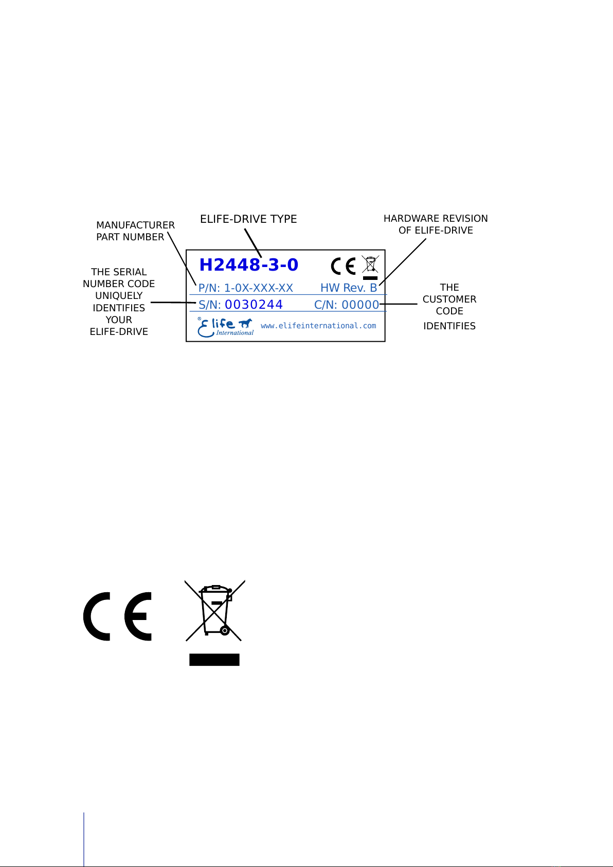
Product Identification Label
Most of information about your Elife-Drive - such as serial number, model, customer
information, etc - can be found on a label located on the front of the Elife-Drive (see
figure below). Some of these information might be requested when you contact the
technical assistance.
THE SERIAL
NUMBER CODE
UNIQUELY
IDENTIFIES
YOUR
ELIFE-DRIVE
ELIFE-DRIVE TYPE HARDWARE REVISION
OF ELIFE-DRIVE
THE
CUSTOMER
CODE
IDENTIFIES
www.elifeinternational.com
0030244 00000S/N: C/N:
HW Rev. B
P/N: 1-0X-XXX-XX
MANUFACTURER
PART NUMBER
H2448-3-0
Compliance with the EU regulatory requirement for electrical and electronic equipment.
When your Elife-Drive is no more usable, can’t be treated as generic garbage, but
must be disposed of at a collection point for recycling of electrical and electronic
equipment, in compliance with the
WEEE
regulation (Waste of Electrical and
Electronic Equipment).
4Chapter 1 Overview

2
Installation and Wiring
2.1 Mounting Elife-Drive on-board
The Elife-Drive can be mounted in any orientation, but you must choose a location
in order to keep the controller
clean
and
dry
, aways from sunlight, water and ice.
When you mount the Elife-Drive on-board you should
ensure an effective heat
dissipation between the Elife-Drive and the vehicle surface.
A thermal grease can be used on the rear side of the Elife-Drive heatsink to
improve the heat exchange between Elife-Drive and the vehicle surface.
Tips and Advice
Elife-Drive has a LED light on the front of the device that visually explains what the
driver is doing (see Section 4.1), if you want it to be visible you should take this into
consideration before choosing the location where your Elife-Drive will be mounted.
In order to ensure the proper functioning of the Elife-Drive you must keep the
controller clean and dry and ensure an effective heat exchange between the
Elife-Drive and the vehicle surface.
Warning
2.2 Connections
Elife-Drive on the front, see Figure 2.1, has different types of connectors:
High Power Connections
The three-phase alternating-current generated by Elife-Drive
is supplied through the
U
,
V
,
W
terminals. The
F+
,
B-
are the positive
1
and
negative terminals to connect to your battery.
Low Power Connections
A 24-pin male connector (
J1 - COMMAND
) for low power
logic control.
1For H4896-X-X Type you must connect an external fuse to the B+ terminal, see Section 2.2.1.
5

Feedback Connections
A 9-pin female low power connector (
J2 - FEEDBACK
) to
connect your feedback board.
Figure 2.1:
Elife-Drive has different types of connectors that can be categorized in: High
Power Connections (
U
,
V
,
W
,
F+
,
B-
,
B+
), Low Power Connections (
J1 - COMMAND
) and
Feedback Connector (J2 - FEEDBACK).
2.2.1 High Power Connections
High power connections are provided by: 3-phase supply terminals (
U
,
V
,
W
) and
two terminals for battery connections (F+ or B+,B-).
In order to connect correctly Elife-Drive, you should use the following instructions:
1.
Except the
H4896-X-X
Type, you must mount an appropriately sized fuse (See
Table 2.2) between
F+
and
B+
terminal to avoid damage to the controller.
All Elife-Drive models, except the
H4896-X-X Type
, have a fuse already
installed.
Note
2.
Connect the
battery positive
cable to the
F+
terminal and the
battery negative
cable to the B- terminal.
For
H4896-X-X
Type you must connect an external fuse to the
B+
terminal
(see Table 2.2 and the Wiring Diagrams).
6Chapter 2 Installation and Wiring

Table 2.1: A summary table of high-power connections, except the H4896-X-X Type.
TERMINAL CONNECT TO
F+ Battery positive terminal to the fuse link
B+ Fuse terminal
B- Battery negative terminal
U,V,W U, V, and W motor phases
3.
Connect the U, V, and W motor phases to the 3-phase supply terminals
(U,V,W).
The tightening torque for high-power connections must be 5.5 N·m.
Note
Make sure when you connect the high-power cables that the feedback cable
passes as far as possible from the power cables and they are not located close
to each other, in order to avoid electromagnetic interference.
Warning
Table 2.2: Fuse size in accordance with the Elife-Drive Type.
ELIFE-DRIVE TYPE FUSE RATING
H2448-2 40 A
H2424-3 100 A
H2436-3 70 A
H2448-3 50 A
H4896-6 70 A
Figure 2.2: Elife-Drive H Series - High-power connections.
2.2 Connections 7
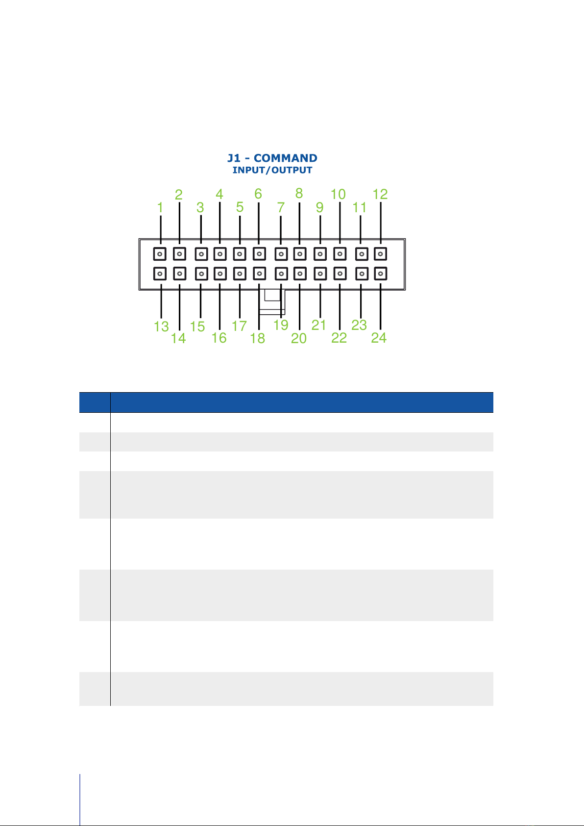
2.2.2 Low Power Connections
The low power logic control connections are provided by a 24-pin male connector
(J1 - COMMAND). The pins’ description is given in Table 2.3.
1
2
3
4
5
6
7
8
9
10
11
12
13
14
15
16
17
18
19
20
21
22
23
24
Table 2.3: The pins’ description for the J1 - COMMAND connector.
PIN I/O TYPE DESCRIPTION OPERATING RANGE
1IN1 Digital input 1 VMAX = 36 V, High > 11 V
2IN3 Digital input 3 VMAX = 36 V, High > 11 V
3IN5 Digital input 5 VMAX = 36 V, High > 11 V
4+24V INPUT
Power supply for output pins, it
should be protected with 4A
delayed fuse, type T
From 6 to 30 V
5BRAKE
Brake supply with
programmable dynamic power
reduction
Output Voltage in according
to the Input voltage on PIN 4
IMAX=2 A
6
LINE
CONTACTOR
OUT
Driver main contactor output
Output Voltage in according
to the Input voltage on PIN 4
IMAX=2 A
7OUT1 Digital output 1
Output Voltage in according
to the Input voltage on PIN 4
IMAX=250 mA
8PWR POT Speed potentiometer supply
output VOUT= 10 V IOUT=100 mA
Continued on next page . . .
8Chapter 2 Installation and Wiring

. . . continued from previous page
PIN I/O TYPE DESCRIPTION OPERATING RANGE
9ANALOG GND Analog Common /
Potentiometer Low Input /
10 CAN-
CAN_L bus line (dominant low)
Standard CAN
11 TX RS232
TX output, it is used to
communicate with RS232 in
order to realize Telemetry panel
Standard RS232
12 SERIAL GND
RS232 Common, it is used to
communicate with RS232 in
order to realize Telemetry panel
/
13 KEY (+BATT)
Internal logic circuits power
supply, it should be protected
with 1A delayed fuse, type T
From 18 to 80 V
(Only for H4896-X-X Type:
From 43 to 160 V)
14 IN2 Digital input 2 VMAX = 36 V, High > 11 V
15 IN4 Digital input 3 VMAX = 36 V, High > 11 V
16 SERVICE Do not use /
17 OUT2 Digital Output 2
Output Voltage in according
to the Input voltage on PIN 4
IMAX=250 mA
18 OUT3
Drive fault alarm output, it
changes its current state
whenever an alarm is present.
See Section 3.4.1, Pag. 37
Output Voltage in according
to the Input voltage on PIN 4
IMAX=250 mA
19 OUT4 Encoder emulator, single phase
Output Voltage in according
to the Input voltage on PIN 4
IMAX=250 mA
20 -BATT
Common ground, it should be
connected to the negative
terminal of battery
/
21 AIN /
WIPER POT
Analog input /
Wiper input for throttle
From 0 to +10 V
From 0 to +5 V
22 CAN+ CAN_H bus line (dominant
high) Standard CAN
23 GND CAN CAN bus common /
24 RX RS232
RX Input, it is used to
communicate with RS232 in
order to realize Telemetry panel
Standard RS232
Concluded
2.2 Connections 9

The digital inputs have over-voltage protection up to battery voltage and the
analog input up to 26 V.
Note
10 Chapter 2 Installation and Wiring

2.3 Standard Wiring Diagrams and Wiring
Instructions
This section contains standard wiring diagrams to be used to connect your
Elife-Drive
H Series
on your system. The following wiring diagrams cover only the standard
operating mode in which the Elife-Drive works to drive a Brushless Servomotor.
It’s also possible to connect two or more Elife-Drive together for specific application
(e.g: steering wheel control) and drive different types of servomotor. These advanced
installations will not be dealt with in the present manual.
The following wiring diagrams and operating instructions should be read
carefully and completed before wiring your Elife-Drive up on your system.
The wiring diagram must be chosen in according to the operating mode
(PLC, Standalone, CAN, RS323) that suits your needs.
Warning
For H4896-6-X Type you should mount an external fuse, see Section 2.2.1.
Note
2.3.1 Standalone Mode
The Standalone mode is designed to drive your motor with only two inputs: a throttle
and a emergency input.
Other optional inputs can be used to extend the functionality of this operating mode
(See Table 2.4).
For the correct functioning of this operating mode, special attention must be paid
to choose the correct value of Analog Input (See Section 3.4.3) in according to the
throttle characteristics.
If you’ve installed a 0-10V or 0-5V throttle the rotation direction of the motor
should be given through the FORWARD and the BACKWARD input.
Note
When
throttle is put to neutral position
- before bridge activation - you can indicate
the speed mode (FAST/SLOW input).
2.3 Standard Wiring Diagrams and Wiring Instructions 11

Table 2.4: Elife-Drive I/O definitions for Standalone Mode.
PIN I/O
TYPE NAME DESCRIPTION
1IN1 CRUISE
Rising Edge Signal = Enable/Disable
Active or Disable the Cruise Control if a
Rising Edge Signal is detected
Optional
14 IN2
FAST/SLOW
High = Slow mode, Low = Fast mode.
This input is processed only before bridge
activation
Optionala
2IN3 FORWARD High = Forward, Low = Stop
(only if BACKWARD is low) Optionalb
BACKWARD
High = Backward, Low = Stop.
This input is only processed if FORWARD
input is low.
Optionalb
15 IN4 REVERSE
High = Active, Low = Inactive.
If it’s active, invert the positive/negative
range of throttle.
Optionalc
3IN5
EMERGENCY
Emergency input should always be
supplied, otherwise Elife-Drive stops
motor rotation and unlocks motor brake.
Mandatory
7OUT1 REVERSE
It is the output to connect to buzzer, it
gets high when the rotation direction is
backward.
17 OUT2 STATUS
It gets steady high when motor is
running and blinking when motor is
stopped. It’s low when there is an alarm.
18 OUT3 ALARM
Alarm output, it changes its current state
whenever an alarm is present. See
Section 3.4.1, Pag. 37
aMandatory if you want to switch between Fast and Slow mode, see Section 3.4.2.
bMandatory only for 0–10V or 0-5V throttle, see Section 3.4.3
cOnly valid for 0–5-10V or 0-2.5-5V throttle, see Section 3.4.3
You can setup accurately the levels of your throttle in the
Tuning Tab
by the
Analog adjustment in Standalone parameters.
Tips and Advice
The Fast and Slow modes are designed to meet two different purposes:
Slow mode
It’s programmable so that the vehicle indoor moves slowly with accurate
operation.
Fast mode It allows a faster velocity for outdoor long distance path.
12 Chapter 2 Installation and Wiring

It’s scheduled both the configuration of the maximum motor velocity and the
maximum velocity at Slow mode (See Section 3.4.2).
The Standalone Mode has a
Cruise Control
. The controller - when the Cruise
Control is activated by a Rising Edge Signal on IN1 - read the actual target velocity
by the throttle state and keep this velocity stable also when the throttle is released.
The Cruise Control are disabled by the following actions:
•A Risign Edge Signal on IN1
•If the Emergency Input is unsupplied.
•For any Alarm Occours.
The
wiring diagram
for standalone mode is shown in Figure 2.3 for any Elife-Drive
H Series Type, except the H4896-X-X Type (Figure 2.4).
2.3 Standard Wiring Diagrams and Wiring Instructions 13

Standalone Mode - Wiring Diagram
BRAKE 24V
24V BUS
GND BUS
KEY
EMERGENCY
1A DELAYED
4A DELAYED
+IN -IN
+OUT -OUT
1A DELAYED
POWER
CONNECTIONS
U
V
W
F+ B+
M
3
B-
FORWARD
MAIN FUSE
24
11
12
16
10
22
23
14
21
18
7
6
20
SIGNAL CONNECTIONS
5
17
19
9
8
4
2
13
3
15
1
CAN PORT RS232
DIGITAL INPUTSDIGITAL OUTPUTS ANALOG I/O SUPPLY
BACKWARD/REVERSE
ALARM
REVERSE
CW
POT +
-
Alternative:
use a voltage source
in place of the pot.
FAST/SLOW
STATUS
RS232-2 TX
RS232-2 RX
RS232-2 GND
OPTIONAL
1A
2A
3A
4A
6A
7A
8A
9A
5A
J2 - FEEDBACK
MOTOR FEEDBACK
Elife-Drive
H Series
CONTACTOR 24V
BATTERY
24 to 48V
DC / DC
Vbatt → 24Vout
@ 6A
VENDOR SPECIFIC
Figure 2.3:
The wiring diagram to connect your
Elife-Drive H Series
- except the H4896-X-X
Type - to your system in Standalone Mode.
14 Chapter 2 Installation and Wiring
This manual suits for next models
7
Table of contents
Popular Servo Drive manuals by other brands

Parker
Parker PSD1-SW1200 installation instructions

Mitsubishi Electric
Mitsubishi Electric MR-J2S-11K Series Instructions and Cautions for Safe Use

Syntec
Syntec SVD-32C1-020 Hardware manual

Omron
Omron R88M-U03030HA user manual

Tsino Dynatron
Tsino Dynatron CoolDrive Series user manual

Estun
Estun Trio DX4 user manual


Omron
Omron OMNUC U Series user manual

Siemens
Siemens SINAMICS S210 FSA Quick installation guide

Metronix
Metronix DIS-2 310/2 FB FS STO Mounting instructions

Rockwell Automation
Rockwell Automation Allen-Bradley Ultra3000 Migration guide

THORLABS
THORLABS KBD101 user guide

Sanyo Denki
Sanyo Denki Sanmotion R manual