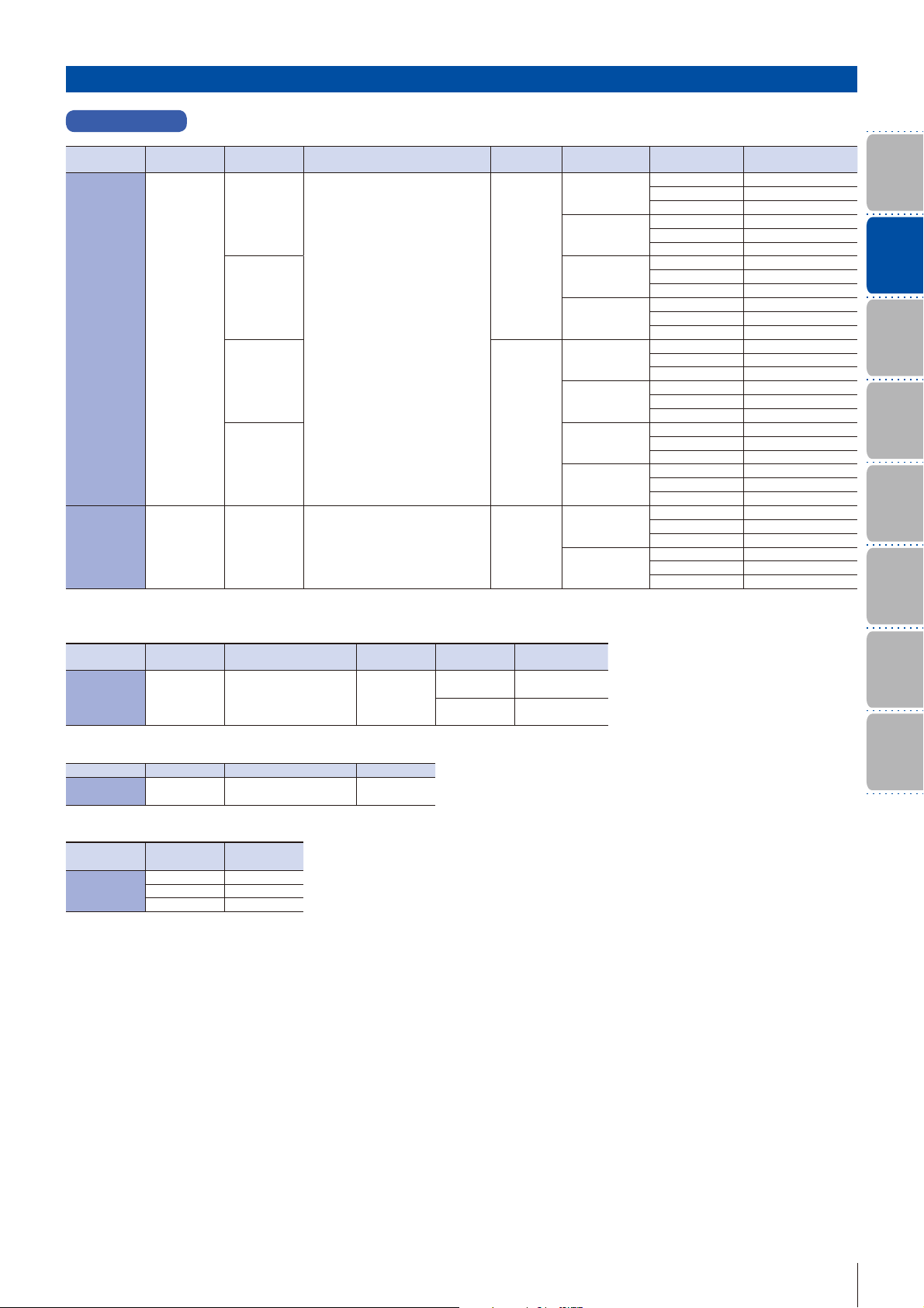
Sanyo Denki Sanmotion R User manual

-~
ARTISAN
®
~I
TECHNOLOGY
GROUP
Your definitive source
for
quality
pre-owned
equipment.
Artisan Technology
Group
Full-service,
independent
repair
center
with
experienced
engineers
and
technicians
on staff.
We
buy
your
excess,
underutilized,
and
idle
equipment
along
with
credit
for
buybacks
and
trade-ins
.
Custom
engineering
so
your
equipment
works
exactly as
you
specify.
•
Critical
and
expedited
services
•
Leasing
/
Rentals/
Demos
• In
stock/
Ready-to-ship
•
!TAR-certified
secure
asset
solutions
Expert
team
ITrust
guarantee
I
100%
satisfaction
All
tr
ademarks,
br
a
nd
names, a
nd
br
a
nd
s a
pp
earing here
in
are
th
e property of
th
e
ir
r
es
pecti
ve
ow
ner
s.
Find the Sanyo Denki RS1A01AC at our website: Click HERE

AC100 V 30 W
-
200 W, AC 200 V 30 W
-
1kW
Ver.6
Artisan Technology Group - Quality Instrumentation ... Guaranteed | (888) 88-SOURCE | www.artisantg.com

Input voltageAC100
V, 200 V
Servo amplifier
5
5
5
5
5
5
A
A
A
A
A
・
・
33
00
AA
A
・
・
55
00
AA
R2 Servo motor
444
4
4
4
4
00
0
0
0
0
0
m
m
mm
mm
・
6
6
6
00
m
m
m
m
・
・
88
8
8
00
mm
m
m
m
m
・
8
8
6
6
m
m
m
m
3
3
3
3
0
0
0
0
0
WW
W
W
W
W
・
55
0
0
W
W
・
・
11
1
0
0
0
0
0
0
0
WW
W
・
・
2
2
0
0
0
0
W
W
・
4
4
4
4
4
0
0
W
・
7
5
0
W
W
・
1
.
0
k
W
Amp. capacity
Flange size
Rated output
Artisan Technology Group - Quality Instrumentation ... Guaranteed | (888) 88-SOURCE | www.artisantg.com

Index
Features and Functions ・・・・・・・・・・・ P. 3
Standard Model Number List ・・・ P. 7
Model Number Nomenclature
・・P. 1 0
System Conguration ・・・・・・・・・・・・P. 1 3
Standard Specications・
Encoder Wiring Diagram ・・・・・・・・P. 1 5
External Wiring Diagram ・・・・・・・・P. 20
Dimensions ・・・・・・・・・・・・・・・・・・・・・・・・・・P. 24
Setup Software ・・・・・・・・・・・・・・・・・・・・・P. 28
Servo Amplier built-in
positioning function・・・・・・・・・・・・・・・P. 30
Optional Equipment・・・・・・・・・・・・・・・P. 31
Discontinued Models and
Replacement Models ・・・・・・・・・・・・・P. 34
Artisan Technology Group - Quality Instrumentation ... Guaranteed | (888) 88-SOURCE | www.artisantg.com

3
Easy Set-up for Optimal Operation
Auto-Tuning
A new auto-tuning algorithm improves system
response by providing functions such as inertia
identification, 5 auto-tuning modes, 30 levels of
response, and parameter setting auto-save.
Tuning start
Velocity command
value
Detected velocity value
Small Compact Servomotors
Motor size and volume is reduced by as much as 30%
and 25% respectively compared to current models.
The world's smallest high torque high performance
servomotor. (as of Sept 2006)
Multi-Axis Servo Amplifier
6-axis model can reduce installation width by up to
42% compared to six single-axis models.Power loss is
reduced by up to 20% compared to current single-axis
models.
Protection code IP67
Protection code is IP67 for all models.
All-in-One Control
Configurable parameters allow you to switch between
control modes for torque, position or velocity.
START
GOAL
Position
or
Velocity
Torque
control
Flat
Ascending
Power Supply Harmonic Suppression
Equipped with DC reactor connection terminals as
standard feature for supressing power supply
harmonics.
30% reduction
*Uniaxial servo amplier only
*Shaft feedthrough and cable end are excluded.
IP67
Water Dust
Artisan Technology Group - Quality Instrumentation ... Guaranteed | (888) 88-SOURCE | www.artisantg.com

4
Standard
Specifications
Model Number
Nomencalture
System
Configuration
Features and
Functions
Optional
Equipment
Dimensions
External Wiring
Diagram
Setup Software
5-digit LED Display, Built-in Operator
Parameter setting, monitoring and alarm tracing can
be easily done using the built-in operator.
Test Function (JOG)
On-board JOG operation function is available for
testing motor and amplifier connection without the
need to connect to host device.
Setup Software
The setup software allows you to set parameters,
view graphical displays of monitored position,
velocity or torque waveforms, and perform system
analysis.
Multiaxial Monitor Function
The setup software allows up to 15 amplifiers to be
monitored. (Single axis only)
Built-in Regeneration Resistor
It is possible to choose whether to equip regenerative
resistance or not. If the regenerative resistance
capability is insufficient, it is possible to use an
external regenerative resistance unit.
Built-in Dynamic Brake
A built-in dynamic brake provides emergency stop
capability. The six kinds of motion sequences for the
dynamic brake can be selected by parameter setting.
*Use optional cable
AL-00490833-01 for PC
connection
Parameter settings Position, velocity,
torque waveforms
*PC connection cable is optional
Maximum
15 units
Built-in
Regeneration
Resistor
External regenerative
resistor unit (Option)
Rotation speed
(min-1)
Time(s)
Controlled
state Dynamic braking state
*Multi-axis is done through a personal computer.
Capable of JOG operation
without connecting to host
device
*
RS232C
Daisy chain up to 15 units
Artisan Technology Group - Quality Instrumentation ... Guaranteed | (888) 88-SOURCE | www.artisantg.com

5
Improved Precision and Reduced CycleTime
High Response
A 4th-order notch filter reduces phase delay to
suppress mechanical resonance and improve velocity
response of equipment.
1
-20
-30
-40
-10
0
10
5 10 50 100 500 1000 1800
Gain (dB)
Frequency (Hz)
Shorter Position Settling Time
A new algorithm drastically shortens positioning
settling time for equipment.
5ms/div
Position deviation
Position complete signal
Settling time (0ms)
Example of positioning settling time
in highly rigid machinery
Vibration Suppression Control
With feed-forward vibration suppression control,
vibrations at the processing point and base of a
machine can be suppressed through simple tuning
procedures. Up to 4 types of vibration control
frequencies can be selected.
100ms/div
Position deviation during stop
Without vibration suppression control
With vibration suppression control
With vibration
suppression control Without vibration
suppression control
Disturbance Suppression
It is possible to control impacts from other axes in
case of multiaxial constitution, by using the new
disturbance observer with extended applicable
frequency.
Oscillation waveform
of direct drive section Oscillation waveform
of direct drive section
Disturbance observer function ON Disturbance observer function OFF
Disturbance
Disturbance
Expanded Power Range
Maximum instantaneous stall torque is improved by
5% to 26%, and maximum rotation speed is increased
from 5000min-1 to 6000min-1 compared to current
models.
07000600050004000300020001000
Rotation Speed
(
min-1
)
R motor
Current model
Increased torque
Increased rotation Speed
Torque (N・m )
Command Follow-up Control
Performance of the positioning doubled in comparison
with current models by adoption of new positioning
control algorithm and new speed control algorithm.
And position deviation≒0 is achieved.
20ms/div
Position deviation
Position command
Artisan Technology Group - Quality Instrumentation ... Guaranteed | (888) 88-SOURCE | www.artisantg.com

6
Standard
Specifications
Model Number
Nomencalture
System
Configuration
Features and
Functions
Optional
Equipment
Dimensions
External Wiring
Diagram
Setup Software
Reduced Running
Costs
Low Cogging Torque
Using our proprietary technology, the motor's low
cogging torque delivers smooth rotation that is ideal
for high precision processes and vibration-sensitive
conveyor applications.
H
i
g
h
R
e
s
o
l
u
t
i
o
n
1
7
b
i
t
(
1
3
1
,
0
7
2
d
i
v
i
s
i
o
n
s
)
A
b
s
o
l
u
t
e
E
n
c
o
d
e
r
20% Reduction in Power Loss
An energy conserving power module reduces main
circuit power loss by up to 20%.
SANMOTION R
50A
70%
60%
50%
40%
30%
20%
10%
0%
80%
90%
100%
Current model
Power loss reduction (%)
High Resolution
Support for encoders up to 17 bit (131,072 divisions) is
available for high resolution control.
R motor
Current model
Comparison of cogging torque waveforms
(*Image)
Artisan Technology Group - Quality Instrumentation ... Guaranteed | (888) 88-SOURCE | www.artisantg.com

7
200V System
Servo Motor Standard Model Number List
For specications on other model, please contact us.
Power Voltage Encoder models
Rated Output Motor Flange Size Holding Brake
CE·UL Model No.
200V
Battery backup method
absolute encoder
(PA035C)
30W 40mm sq.
――
R2AA04003FXP00
―Standard R2AA04003FXP00M
yes
(24V)―
R2AA04003FCP00
yes
(24V)Standard R2AA04003FCP00M
50W 40mm sq.
――
R2AA04005FXP00
―Standard R2AA04005FXP00M
yes
(24V)―
R2AA04005FCP00
yes
(24V)Standard R2AA04005FCP00M
100W
40mm sq. ――
R2AA04010FXP00
―Standard R2AA04010FXP00M
60mm sq.
――
R2AA06010FXP00
―Standard R2AA06010FXP00M
yes
(24V)―
R2AA06010FCP00
yes
(24V)Standard R2AA06010FCP00M
200W
60mm sq.
――
R2AA06020FXP00
―Standard R2AA06020FXP00M
yes
(24V)―
R2AA06020FCP00
yes
(24V)Standard R2AA06020FCP00M
80mm sq.
――
R2AA08020FXP00
―Standard R2AA08020FXP00M
yes
(24V)―
R2AA08020FCP00
yes
(24V)Standard R2AA08020FCP00M
400W
60mm sq. ――
R2AA06040FXP00
―Standard R2AA06040FXP00M
80mm sq.
――
R2AA08040FXP00
―Standard R2AA08040FXP00M
yes
(24V)―
R2AA08040FCP00
yes
(24V)Standard R2AA08040FCP00M
750W 80mm sq.
――
R2AA08075FXP00
―Standard R2AA08075FXP00M
yes
(24V)―
R2AA08075FCP00
yes
(24V)Standard R2AA08075FCP00M
1000W 86mm sq.
――
R2AAB8100FXP00
―Standard R2AAB8100FXP00M
yes
(24V)―
R2AAB8100FCP00
yes
(24V)Standard R2AAB8100FCP00M
Absolute encoder for
incremental System
(PA035S)
30W 40mm sq.
――
R2AA04003FXH00
―Standard R2AA04003FXH00M
yes
(24V)―
R2AA04003FCH00
yes
(24V)Standard R2AA04003FCH00M
50W 40mm sq.
――
R2AA04005FXH00
―Standard R2AA04005FXH00M
yes
(24V)―
R2AA04005FCH00
yes
(24V)Standard R2AA04005FCH00M
100W
40mm sq. ――
R2AA04010FXH00
―Standard R2AA04010FXH00M
60mm sq.
――
R2AA06010FXH00
―Standard R2AA06010FXH00M
yes
(24V)―
R2AA06010FCH00
yes
(24V)Standard R2AA06010FCH00M
200W
60mm sq.
――
R2AA06020FXH00
―Standard R2AA06020FXH00M
yes
(24V)―
R2AA06020FCH00
yes
(24V)Standard R2AA06020FCH00M
80mm sq.
――
R2AA08020FXH00
―Standard R2AA08020FXH00M
yes
(24V)―
R2AA08020FCH00
yes
(24V)Standard R2AA08020FCH00M
400W
60mm sq. ――
R2AA06040FXH00
―Standard R2AA06040FXH00M
80mm sq.
――
R2AA08040FXH00
―Standard R2AA08040FXH00M
yes
(24V)―
R2AA08040FCH00
yes
(24V)Standard R2AA08040FCH00M
750W 80mm sq.
――
R2AA08075FXH00
―Standard R2AA08075FXH00M
yes
(24V)―
R2AA08075FCH00
yes
(24V)Standard R2AA08075FCH00M
1000W 86mm sq.
――
R2AAB8100FXH00
―Standard R2AAB8100FXH00M
yes
(24V)―
R2AAB8100FCH00
yes
(24V)Standard R2AAB8100FCH00M
Artisan Technology Group - Quality Instrumentation ... Guaranteed | (888) 88-SOURCE | www.artisantg.com

8
Standard
Specifications
Model Number
Nomencalture
System
Configuration
Features and
Functions
Optional
Equipment
Dimensions
External Wiring
Diagram
Setup Software
200V System
Type Main Power Control Power Encoder Type Selectable
Output
Internal Registration
Resistor
Amplier
Capacity Model No.
CANopen
Interface
specications
AC200V
System
AC200V
System
Wire-saving incremental encoder,
Battery backup method absolute
encoder
NPN
―
15A RS1A01AL
30A RS1A03AL
50A RS1L05AL
With
15A RS1L01AL
30A RS1L03AL
50A RS1A05AL
DC24V
―
15A RS1J01AL
30A RS1J03AL
50A RS1J05AL
With
15A RS1K01AL
30A RS1K03AL
50A RS1K05AL
AC200V
System
PNP
―
15A RS1A01AU
30A RS1A03AU
50A RS1L05AU
With
15A RS1L01AU
30A RS1L03AU
50A RS1A05AU
DC24V
―
15A RS1J01AU
30A RS1J03AU
50A RS1J05AU
With
15A RS1K01AU
30A RS1K03AU
50A RS1K05AU
Built-in
positioning
function
model
AC200V
System AC200V
System
Wire-saving incremental encoder,
Battery backup method absolute
encoder
NPN
―
15A RS1A01AC
30A RS1A03AC
50A RS1L05AC
With
15A RS1L01AC
30A RS1L03AC
50A RS1A05AC
For specications on other model, please contact us.
Type Power Input Encoder Type Selectable
Output
Amplier
Capacity Model No.
Pulse train
interface DC280V Battery backup method
absolute encoder NPN
15A RR1A01AAB00
30A RR1A03AAB00
■
Multi-Axis Servo System Amplier Unit
Type Power Input
Internal Registration Resistor
Model No.
Pulse train
interface AC200V With RRPAA00
■
Multi-Axis Servo System Power Unit
Power Input
Number of Slots
(based on a 15A unit)
Model No.
AC200V
4RRMA400
6RRMA600
8RRMA800
■
Multi-Axis Servo System Motherboard
Servo Amplifier Standard Model Number List
Artisan Technology Group - Quality Instrumentation ... Guaranteed | (888) 88-SOURCE | www.artisantg.com

9
Power Voltage Encoder models
Rated Output Motor Flange Size
Holding Brake CE·UL Model No.
100V
Battery backup method
absolute encoder
(PA035C)
30W 40mm sq.
yes(24V) ―R2EA04003FCP00
yes(24V) Standard R2EA04003FCP00M
――
R2EA04003FXP00
―Standard R2EA04003FXP00M
50W 40mm sq.
yes(24V) ―R2EA04005FCP00
yes(24V) Standard R2EA04005FCP00M
――
R2EA04005FXP00
―Standard R2EA04005FXP00M
80W 40mm sq.
yes(24V) ―R2EA04008FCP00
yes(24V) Standard R2EA04008FCP00M
――
R2EA04008FXP00
―Standard R2EA04008FXP00M
100W 60mm sq.
yes(24V) ―R2EA06010FCP00
yes(24V) Standard R2EA06010FCP00M
――
R2EA06010FXP00
―Standard R2EA06010FXP00M
200W 60mm sq.
yes(24V) ―R2EA06020FCP00
yes(24V) Standard R2EA06020FCP00M
――
R2EA06020FXP00
―Standard R2EA06020FXP00M
Absolute encoder for
incremental System
(PA035S)
30W 40mm sq.
yes(24V) ―R2EA04003FCH00
yes(24V) Standard R2EA04003FCH00M
――
R2EA04003FXH00
―Standard R2EA04003FXH00M
50W 40mm sq.
yes(24V) ―R2EA04005FCH00
yes(24V) Standard R2EA04005FCH00M
――
R2EA04005FXH00
―Standard R2EA04005FXH00M
80W 40mm sq.
yes(24V) ―R2EA04008FCH00
yes(24V) Standard R2EA04008FCH00M
――
R2EA04008FXH00
―Standard R2EA04008FXH00M
100W 60mm sq.
yes(24V) ―R2EA06010FCH00
yes(24V) Standard R2EA06010FCH00M
――
R2EA06010FXH00
―Standard R2EA06010FXH00M
200W 60mm sq.
yes(24V) ―R2EA06020FCH00
yes(24V) Standard R2EA06020FCH00M
――
R2EA06020FXH00
―Standard R2EA06020FXH00M
Type Power Input Encoder Type Selectable
Output
Amplier
Capacity Model No.
Pulse train
interface DC140V Battery backup method
absolute encoder NPN
15A RR1E01AAB00
30A RR1E03AAB00
■
Multi-Axis Servo System Amplier Unit
Type Power Input
Internal Registration Resistor
Model No.
Pulse train
interface AC100V With RRPEA00
■
Multi-Axis Servo System Power Unit
Power Input
Number of Slots
(based on a 15A unit)
Model No.
AC100V
4RRME400
6RRME600
8RRME800
■
Multi-Axis Servo System Motherboard
Type Main Power Control Power Encoder Type Selectable
Output
Internal Registration
Resistor
Amplier
Capacity Model No.
Built-in
positioning
function
model
AC100V
System AC100V
System
Wire-saving incremental encoder,
Battery backup method absolute
encoder
NPN
With 15A RS1N01AC
30A RS1N03AC
―15A RS1E01AC
30A RS1E03AC
For specications on other model, please contact us.
100V System
Servo Amplifier Standard Model Number List
100V System
Servo Motor Standard Model Number List
For specications on other model, please contact us.
Artisan Technology Group - Quality Instrumentation ... Guaranteed | (888) 88-SOURCE | www.artisantg.com

10
Standard
Specifications
Model Number
Nomencalture
System
Configuration
Features and
Functions
Optional
Equipment
Dimensions
External Wiring
Diagram
Setup Software
Servo Motor Model Number Nomenclature
R
モータ種別
‥‥‥中慣性
Rated Output
003 ‥‥‥ 30W
005 ‥‥‥ 50W
010 ‥‥‥ 100W
020 ‥‥‥200W
040 ‥‥‥ 400W
075 ‥‥‥ 750W
100 ‥‥‥ 1kW
FC APM2 AA 06 020 00
A
B
C
D
E
S
T
U
V
1/3
1/5
1/9
1/15
1/25
1/5
1/11
1/21
1/33
Planetary
gear
Backlashless
planetary
gear
Symbol
R Series
Motor Type
‥‥Middle inertia
Supply Voltage
AA‥200V Motor
EA‥100V Motor
Flange Size
04 ‥‥‥40mm
06 ‥‥‥60mm
08 ‥‥‥80mm
B8‥‥‥86mm Encoder Type
P‥Battery backup method absolute encoder[PA035C]
H‥Absolute encoder for incremental System[PA035S]
W‥Absolute encoder without battery[RA035C]
S‥Wire-saving incremental encoder[PP031T]
Maximum Rotation Speed
‥‥6000min-1
Holding Brake
X‥‥Without Brake
B‥‥With Brake(90V DC)
C‥‥With Brake(24V DC)
00‥Standard
01‥With oil seal
Specification
Standard Identification
M ‥‥CE and UL
0 ‥‥Without standard
but with gear
Reducer type
Please consult with us about the
combination for the decelerator.
Reduction ratio
Example: The following model number defines a "R2" servomotor with 60mm flange size, 200W rated output,
6000min-1 maximum rotation speed, 24V brake, and an absolute encoder (131,072 divisions/
rotation),UL/CE approval and reduction ratio 1/3.(Planetary gear)
Servo Motor
Encoder Specification
PA035C
PA035S
131072(17bit) 65536(16bit) Battery backup method Absolute encoder
131072(17bit) ーAbsolute encoder for Incremental system
Partition number /
rotation
Multiple Rotations
Model Remarks
RA035C
PP031T
131072(17bit)
8000(2000P/R)
65536(16bit)
ー
Absolute encoder without battery
Wire-saving incremental encoder
Maximum 40000(Partition number/ rotation)
A reduction in the rating might be needed if an oil seal
and Brake is attached. Please consult with us about the details.
Our standard servo amplifier has attained the international
standards (UL, c-UL and EN Standards).
You can also employ servo motors that have attained the
international standards (UL, c-UL and EN Standards).
Conformance to Overseas Standards
Artisan Technology Group - Quality Instrumentation ... Guaranteed | (888) 88-SOURCE | www.artisantg.com

11
AMP. Capacity
Motor Type
L
A
AC200V
15A,30A
Model AMP. Capacity
A
L
N
E
AC100V
15A,30A
50A
50A
15A,30A
15A,30A
Power Input, Internal Registration Setting
W
Internal Registration
Resistor
W/O
W
W/O
W
W/O
K
J
DC24V W
W/O
AC200V
AC100V
AC200V
Control Power
Input Voltage
Power Input,
Input Voltage
15A,30A,50A
15A,30A,50A
01‥‥‥ 15A
03‥‥‥ 30A
05‥‥‥ 50A
‥‥‥Rotary Motor
AA 01RS1
Interface Type
Interface Specification:CAN open I/F
Encoder Specification:Absolute encoder,
Wire-saving incremental encoder
L‥‥NPN Output
U‥‥PNP Output
L
R Series
Single-Axis Servo
Amplifier
Servo Amplifier with CANopen
Servo Amplifier Model Number Nomenclature
Example: The model number shown below is "R" Series Servo Amplifier with 200V AC input voltage and 15A
amplifier capacity.
Single-Axis Servo Amplifier built-in Positioning Function model
Example: The model number shown below is "R" Series Servo Amplifier with 200V AC input voltage
(Main Power and Control Power) and 15A amplifier capacity.
R Series
Single-Axis Servo
Amplier
Amp. capacity
01‥‥‥ 15A
03‥‥‥ 30A
05‥‥‥ 50A Motor Type
‥‥‥Rotary Motor
ACA01RS1
L
A
AC200V
InputVoltage
W
Model
A
L
N
E
AC100V
Internal Registration Resistor
W/O
W
W/O
W
W/O
15A,30A
Amp. capacity
15A,30A
50A
50A
15A,30A
15A,30A
Power Input, Internal Registration Setting Interface Type
C‥‥Built-in Positioning Function Model
F‥‥Built-in positioning function model
with serial interface
*The motor parameters need to be set for the amplier for use. Use the setup software.
Artisan Technology Group - Quality Instrumentation ... Guaranteed | (888) 88-SOURCE | www.artisantg.com

12
Standard
Specifications
Model Number
Nomencalture
System
Configuration
Features and
Functions
Optional
Equipment
Dimensions
External Wiring
Diagram
Setup Software
R Series
Multi-Axis Servo System
Amplier Unit
Amp. capacity
01‥‥‥ 15A
03‥‥‥ 30A
Motor Type
‥‥‥Rotary Motor
Encoder Combination Description
‥‥‥Absolute encoder
Control Hardware Type
‥‥‥Pulse train interface
AAA01RR1 B00
Power Input
Specication
‥‥Standard
Amplier Unit
R Series
Multi-Axis Servo System
Motherboard
Control Hardware Type
‥‥‥Pulse train interface
A
A
RRP 00
Specication
‥‥Standard
4
A
RRM 00
Motherboard
Power Unit
R Series
Multi-Axis Servo System
Power Unit
A
‥‥
DC280V
E
‥‥
DC140V
Power Input
A
‥‥
AC200V
E
‥‥
AC100V
Power Input
A
‥‥
AC200V
E
‥‥
AC100V
Number of Slots
4‥‥‥4 Slots
6‥‥‥6 Slots
8‥‥‥8 Slots
Amplier Unit 15A:Use of 1 slot per 1 unit
Amplier Unit 30A:Use of 2 slots per 1 unit
Specication
‥‥Standard
Example: The model number shown below is a 4-axis "R" series multiaxis servo amplifier configuration
with 200V AC input voltage, 4 units of 15A amplifiers, and pulse train interface.
Amplier Unit RR1A01AAB00 ×4 units
Power Unit RRPAA00
×1 unit
Motherboard RRMA400
×1 unit
Multi-Axis Servo Amplifier
*The motor parameters need to be set for the amplier for use. Use the setup software.
Artisan Technology Group - Quality Instrumentation ... Guaranteed | (888) 88-SOURCE | www.artisantg.com

13
Single-Axis Servo Amplifier
T S R
CN2
PC
Model No.: AL-00490833-01
Wiring required for brake.
CN1 Host Devices
Parameter
conguration
and monitoring
is possible via
communication
with a PC.
Setup
Software
Cuts off power in the case
of an overload, to protect
the power line.
Circuit Breaker(MCCBM)
Attached to prevent
external noise from the
power source line.
Noise Filter
For special operations, such as
high frequency applications
that require greater power
dissipation than that provided
by the servo amplier’s
internal regenerative resistor.
External Regenerative Resistor
Use as necessary, for example
when operating loads with
large inertia.
Switches servo power on and
off. Installation of a surge
protector is required.
Create the protective circuit.
DC Reactor
Suppresses power harmonics.
Remove the short bar between
DL1-DL2 and connect this here,
when needed for high
frequency waves.
Electromagnetic Contactor
Required for use when the
servo motor is equipped
with a brake.
Brake Power
PLC
When using the unit with an
absolute system, mount the
optional battery inside the
digital operator cover.
Model No.: AL-00494635-01 Lithium battery
CANopen
System Configuration
Dedicated controller
PC and PLC are available
as the host device.
*Communication Profile: DS-301
Device Profile: DSP-402 compliance
Host Devices
Artisan Technology Group - Quality Instrumentation ... Guaranteed | (888) 88-SOURCE | www.artisantg.com

T
S
R
Host Devices
Parameter conguration
and monitoring is possible
via communication with a
PC.
Setup Software
Cuts off power in the case
of an overload, to protect
the power line.
Circuit Breaker(MCCB)
Attached to prevent
external noise from the
power source line.
Noise Filter
Required for use when the
servo motor is equipped
with a brake.
Brake Power
Wiring required for brake.
PLC
Switches servo power on and
off. Installation of a surge
protector is required.
Create the protective circuit.
Electromagnetic Contactor
DC Reactor
Suppresses power harmonics.
Remove the short bar between
DL1-DL2 and connect this here,
when needed for high
frequency waves.
For special operations, such as
high frequency applications
that require greater power
dissipation than that provided
by the servo amplier’s
internal regenerative resistor.
External Regenerative Resistor
Use as necessary, for example
when operating loads with
large inertia.
Model No.: AL-00490833-01
When using the unit with
an absolute system,
connect the battery to
CN5.
Lithium battery
14
Standard
Specifications
Model Number
Nomencalture
System
Configuration
Features and
Functions
Optional
Equipment
Dimensions
External Wiring
Diagram
Setup Software
Multi-Axis Servo Amplifier
Artisan Technology Group - Quality Instrumentation ... Guaranteed | (888) 88-SOURCE | www.artisantg.com

15
R2
Servo Motor
Capacity
40mm sq. to 86mm sq.
30W to 1000W
Features
High Efficiency and Low
Ripple (Medium Inertia)
Motor Model and Flange Size in mm R2AA04003F
《40》
R2AA04005F
《40》
R2AA04010F
《40》
Status Symbol
Unit
Rated Output ★PRW30 50 100
Rated Speed ★NRmin-1 3000
Maximum Speed ★Nmax min-1 6000
Rated Torque ★TRN・m0.098 0.159 0.318
Continuous Torque at Stall ★TSN・m0.108 0.167 0.318
Peak Torque at Stall ★TPN・m0.37 0.59 1.18
Rated Armature Current ★IRArms 0.51 0.67 0.81
Armature Current at Stall ★ISArms 0.56 0.69 0.81
Peak Armature Current at Stall ★IPArms 2.15 2.8 3.3
Torque Constant ☆KTN・m/Arms 0.201 0.246 0.424
Voltage Constant Per Phase ☆KEφmV/min-1 78.614.8
Phase Resistance ☆RφΩ12 9 9.3
Rated Power Rate ★QRkW/s3.9 6.7 16
Electrical Time Constant ☆te ms 0.55 0.67 0.82
Mechanical Time Constant (Not including Encoder)
☆tm ms 2.2 1.7 0.97
Rotor Moment of Inertia (Not including Encoder)
JM
×10-4 kg・m2
(GD2/4)
0.0247 0.0376 0.0627
Rotor Moment of Inertia (Encoder) JS
×10-4 kg・m2
(GD2/4)
0.0033 (Note 3)
Mass including Encoder WE kg 0.35 0.39 0.51
Brake Static Friction Torque TB N・m0.32 MIN.
Brake Rated Voltage VB V DC90V /DC24V ±10%
Brake Rated Current IB A 0.07 /0.27
Rotor Moment of Inertia (Brake) JB
×10-4 kg・m2
(GD2/4)
0.0078
Brake Mass Wkg 0.27
Motor Operating Temp, Rel. Humidity
Operating Temperature: 0 to 40°C, Relative Humidity: 90% Maximum, no condensation
Amplier Model
(Single-Axis
)
RS1A01A□
Amplier Model
(Multi-Axis
)
RR1A01AAB00
Amplier Power Supply AC200V to 230V +10, −15% 50/60Hz ±3Hz (Note 2)
Amp. Operating Temp. and RH
Operating Temperature: 0 to 55°C (Note1), Relative Humidity: 90%
M
aximum, no condensation
Rated power supply kVA 0.2 0.4
Amplier Mass
(
Weight
)
[Single / CAN / Multi]
(Note4)
kg 0.9 /1.0 /0.48
Motor Dwgs
P24
★:Indicates a typical value
after warm-up and thermal
stabilization, together with
a standard amplifier.
☆:Indicates a typical
value when the winding
temperature is 20℃.
200V System
ES+
ES−
EBAT+
EBAT−
ES+
ES−
EBAT+
EBAT−
CN2 13
14
1
2
9
10
11
12
17
18
19
20
+5V
0V
Note1)
Note3)
Note2)
Note2)
Brown
Blue
Pink
Purple
Red
Black
+5V
0V
FG(Shielded)
Encoder
Plug:10120-3000PE
Shell:10320-52A0-008
Note4)
SERVO AMPLIFIER SERVO MOTOR
Note 1)
Note 2)
Note 3)
Note 4)
Use a Awg24 0.2mm2encoder cable
When the Absolute encoder for incremental system or absolute encoder
without battery is used, battery lines (EBAT+, EBAT-) are not required.
+5V DC Wiring Connect pin 19
(Do not connect pins12,17)
Connect pin 20
(Do not connect pins11,18)
Connect pin 17,19
(Do not connect pins12)
Connect pin 18,20
(Do not connect pins11)
Connect pin 12,17,19
Connect pin 11,18,20
0V DC Wiring
10m MAX. 25m MAX. 40m MAX.
Use a twisted-pair shielded cable.
Encoder power connections depend on encoder cable length. See the following
Encoder cable length
Battery backup method absolute encoder [ PA035C ]
Absolute encoder for incremental system [ PA035S ]
Absolute encoder without battery [ RA035C ]
Single-Axis Servo Amplifier
Note 1) The multi-axis type Servo amplifier has an ambient
operating temperature of 0 to 40℃. The operating
temperature with forced air cooling is 0 to 55℃.
Note 2) In case of the amplifier for CANopen, there is also
control power source DC24V type.
Note 3) This is a instance with the battery-backup method
absolute encoder
〔PA035〕.
For the following encoders, please make inquiries:
・Absolute encoder without battery[RA035C ]
・Red. Wiring Incremental Encoder[PP031T ]
Note 4) The weight in the multi-axial specifications is of amplifier
unit only.
* For models with oil seal or brake, reduction in rated value
may become necessary.
・
Multi-Axis Servo Amplier Wiring diagram →page17
Standard Specifications
Encoder Wiring Diagram
0
7000600050004000300020001000
0
0.1
0.2
0.4
0.3
0.5
Speed [min-1]
Torque [N
・m]
0
7000600050004000300020001000
0
Speed [min-1]
Torque [N
・m]
0.2
0.4
0.6
0.8
0
7000600050004000300020001000
0
Speed [min-1]
Torque [N
・m]
0.5
1
1.5
Artisan Technology Group - Quality Instrumentation ... Guaranteed | (888) 88-SOURCE | www.artisantg.com

16
Standard
Specifications
Model Number
Nomencalture
System
Configuration
Features and
Functions
Optional
Equipment
Dimensions
External Wiring
Diagram
Setup Software
R2AA06010F
《60》
R2AA06020F
《60》
R2AA06040F
《60》
R2AA08020F
《80》
R2AA08040F
《80》R2AA08075F
《80》
R2AAB8100F
《86》
100 200 400 200 400 750 1000
3000
6000
0.318 0.637 1.27 0.637 1.27 2.39 3.18
0.353 0.686 1.37 0.686 1.37 2.55 3.92
1.13 2.2 4.8 2.2 4.4 8.5 14.3
0.86 1.5 2.8 1.5 2.6 4.6 6.0
0.86 1.6 2.8 1.5 2.6 4.6 6.8
3.5 5.6 10.8 4.8 8.9 15.5 25.7
0.375 0.476 0.524 0.516 0.559 0.559 0.582
13.1 16.6 18.3 18.0 19.5 19.5 20.3
4.8 2.7 1.36 2.3 0.93 0.4 0.44
8.6 19 39 81631 42
2.0 2.6 3.2 2.2 2.5 3.0 4.3
1.2 0.78 0.61 1.3 0.93 0.70 0.93
0.117 0.219 0.412 0.52 1.04 1.82 2.38
0.0033 (Note 3)
0.71 0.96 1.4 1.3 1.7 2.7 3.6
0.36 MIN. 1.37 MIN. 2.55 MIN. 3.92 MIN.
DC90V /DC24V ±10%
0.07 /0.27 0.11 /0.32 0.12 /0.37 0.30 /0.09
0.060 0.060 0.25 0.34
0.34 0.37 0.89 0.84
Operating Temperature: 0 to 40°C, Relative Humidity: 90%
M
aximum, no condensation
RS1A01A□RS1A03A□RS1A01A□RS1A03A□RS1A05A□
RR1A01AAB00 RR1A03AAB00 RR1A01AAB00 RR1A03AAB00 ―
AC200V to 230V +10, −15% 50/60Hz ±3Hz (Note 2)
Operating Temperature: 0 to 55°C(Note), Relative Humidity: 90%
M
aximum, no condensation
0.4 0.8 1.0 0.8 1.0 1.7 2.5
0.9 /1.0 /0.48 1.0 /1.1 /0.77 0.9 /1.0 /0.48 1.0 /1.1 /0.77 2.2 /2.3 /–
SERVO AMPLIFIER SERVO MOTOR
3
4
5
6
7
8
9
10
11
12
16
17
18
19
20
CN2
Aor U
channel input
Aor U
channel input
Bor V
channel input
Bor V
channel input
Cor W
channel input
Cor W
channel input
+DC 5V
GND(0V)
+DC 5V
GND(0V)
Aor U
channel output
Aor U
channel output
Bor V
channel output
Bor V
channel output
Cor W
channel output
Cor W
channel output
Blue
Brown
Green
Purple
White
Yellow
Red
Black
Note 2)
Note 2)
Note 1)
Note 3)
Note 3)
FG(Shielded)
Plug : 10120-3000PE,
Shell : 10320-52A0-008
Incremental encoder Note 1)
Note 2)
Use a twisted-pair shielded cable.
Encoder power connections depend on encoder cable length. See the following
Note 3) Use a Awg24 0.2mm2encoder cable
Encoder cable length
+5V DC Wiring Connect pin 19
(Do not connect pins 9,12,17)
Connect pin 20
(Do not connect pins10,11,16,18)
Connect pin 17,19
(Do not connect pins 9,12)
Connect pin 18,20
(Do not connect pins 10,11,16)
9,12,17,19 Connect pin
10,11,16,18,20Connect pin
0V DC Wiring
5m MAX. 10m MAX. 30m MAX.
Connect pin 12,17,19
(Do not connect pins 9)
Connect pin 11,18,20
(Do not connect pins 10,16)
20m MAX.
Wire-saving incremental encoder [ PP031T ]
Single-Axis Servo Amplifier
0
7000600050004000300020001000
0
Speed [min-1]
Torque [N
・m]
2
4
8
6
10
0
7000600050004000300020001000
0
Speed [min-1]
Torque [N
・m]
0.5
1
1.5
0
7000600050004000300020001000
0
Speed [min-1]
Torque [N
・m]
1
2
3
0
7000600050004000300020001000
0
Speed [min-1]
Torque [N
・m]
1
2
3
4
5
6
0
7000600050004000300020001000
0
Speed [min-1]
Torque [N
・m]
1
2
3
0
7000600050004000300020001000
0
Speed [min-1]
Torque [N
・m]
1
2
3
4
5
6
Torque [N
・m]
Speed [min-1]
0
7000600050004000300020001000
0
5
10
15
Artisan Technology Group - Quality Instrumentation ... Guaranteed | (888) 88-SOURCE | www.artisantg.com

17
R2
Servo Motor
Capacity
40mm sq. to 60mm sq.
30W to 200W
(5models)
Features
High Efficiency and Low
Ripple (Medium Inertia)
Motor Model and Flange Size in mm R2EA04003F
《40》
R2EA04005F
《40》
Status Symbol
Unit
Rated Output ★PRW30 50
Rated Speed ★NRmin-1 3000
Maximum Speed ★Nmax min-1 6000
Rated Torque ★TRN・m0.098 0.159
Continuous Torque at Stall ★TSN・m0.108 0.167
Peak Torque at Stall ★TPN・m0.37 0.59
Rated Armature Current ★IRArms 0.94 1.2
Armature Current at Stall ★ISArms 1.0 1.3
Peak Armature Current at Stall ★IPArms 3.7 4.9
Torque Constant ☆KTN・m/Arms 0.116 ±10% 0.142 ±10%
Voltage Constant Per Phase ☆KEφmV/min-1 4.04 ±10% 4.97 ±10%
Phase Resistance ☆RφΩ43
Rated Power Rate ★QRkW/s3.9 6.7
Electrical Time Constant ☆te ms 0.55 0.67
Mechanical Time Constant (Not including Encoder)
☆tm ms 2.2 1.7
Rotor Moment of Inertia (Not including Encoder)
JM
×10-4 kg・m2
(GD2/4)
0.0247 0.0376
Rotor Moment of Inertia (Encoder) JS
×10-4 kg・m2
(GD2/4)
0.0033 (Note 2)
Mass including Encoder WE kg 0.35 0.39
Brake Static Friction Torque TB N・m0.32 MIN.
Brake Rated Voltage VB V DC90V /DC24V ±10%
Brake Rated Current IB A 0.07 /0.27
Rotor Moment of Inertia (Brake) JB
×10-4 kg・m2
(GD2/4)
0.0078
Brake Mass Wkg 0.27
Motor Operating Temp, Rel. Humidity
Operating Temperature: 0 to 40°C, Relative Humidity: 90% Maximum, no condensation
Amplier Model
(Single-Axis
)
RS1E01A□
Amplier Model
(Multi-Axis
)
RR1E01AAB
Amplier Power Supply AC100V to 115V +10,− 15% 50/60Hz ± 3Hz
Amp. Operating Temp. and RH
Operating Temperature: 0 to 55°C (Note1), Relative Humidity: 90%
M
aximum, no condensation
Rated power supply kVA 0.2
Amplier Mass
(
Weight
)
[Single / Multi]
kg 0.9 /0.48
Motor Dwgs
P24
★:Indicates a typical value
after warm-up and thermal
stabilization, together with
a standard amplifier.
☆:Indicates a typical
value when the winding
temperature is 20℃.
100V System
0
7000600050004000300020001000
0
Torque [N
・m]
Speed [min-1]
0.1
0.2
0.4
0.3
0.5
0
7000600050004000300020001000
0
Torque [N
・m]
Speed [min-1]
0.2
0.4
0.6
0.8
Note 1) The multi-axis type Servo amplifier has an ambient
operating temperature of 0 to 40℃. The operating
temperature with forced air cooling is 0 to 55℃.
Note 2) This is a instance with the battery-backup method
absolute encoder
〔PA035〕.
For the following encoders, please make inquiries:
・Absolute encoder without battery[RA035C ]
・Red. Wiring Incremental Encoder[PP031T ]
Note 3) The weight in the multi-axial specifications is of amplifier
unit only.
* For models with oil seal or brake, reduction in rated value
may become necessary.
Multi-Axis Servo Amplifier
SERVO AMPLIFIER SERVO MOTOR
0V
+5V
+5V
0V
+5
0V
1
2
3
4
5
6
N.C.
N.C.
10
9
8
7
EBAT
-
ES+
EBAT+
ES
-
EBAT
-
ES+
EBAT+
ES
-
Note 2)
Plug:36320-0100JL
Shell:36310-3200-008
Note 1)
Black
Red
Purple
Pink
Blue
Brown
Note 3)
The sheathed shield wire should be connected to the metal case (ground) on CN2 side,
before connecting to ground on encoder side.
Color symbols shown on the diagram for signal lines on encoder side refer to lead-wire
type sensors.
Note 1)
Note 2)
Note 3)
Note 4) The allowable connection distance between amplifier and encoder varies according to
the diameter(impedence) of the electric wire of the cable used.The power voltage
specification for encoders is 5V±5%. If the cable is too long, the voltage on encoder side
may fall below 5V.Measure the voltage on encoder side to ensure that the cable used is
within specification limits.
Use a twisted-pair shielded cable.
Encoder
FG(Shielded)
Battery backup method absolute encoder [ PA035C ]
For the following encoders, please make inquiries:
・
Absolute encoder without battery
[RA035C ]
Standard Specifications
Encoder Wiring Diagram
Artisan Technology Group - Quality Instrumentation ... Guaranteed | (888) 88-SOURCE | www.artisantg.com

18
Standard
Specifications
Model Number
Nomencalture
System
Configuration
Features and
Functions
Optional
Equipment
Dimensions
External Wiring
Diagram
Setup Software
R2EA04008F
《40》
R2EA06010F
《60》
R2EA06020F
《60》Unit
80 100 200 W
3000 min-1
6000 min-1
0.255 0.318 0.637 N・m
0.255 0.318 0.686 N・m
0.86 1.0 2.2 N・m
1.3 1.7 3.1 Arms
1.3 1.7 3.2 Arms
4.5 5.6 11.9 Arms
0.221 ±10% 0.206 ±10% 0.224 ±10% N・m/Arms
7.7 ±10% 7.2 ±10% 7.82 ±10% mV/min-1
2.9 1.5 0.6 Ω
10 8.6 19 kW/s
0.81 1.9 2.6 ms
0.98 1.2 0.79 ms
0.0627 0.117 0.219
×10-4 kg・m2
(GD2/4)
0.0033 (Note 2)
×10-4 kg・m2
(GD2/4)
0.51 0.71 0.76 kg
0.32 MIN. 0.36 MIN. 1.37 MIN. N・m
DC90V /DC24V ±10%V
0.07 /0.27 0.07 /0.27 0.11 /0.32 A
0.0078 0.06
×10-4 kg・m2
(GD2/4)
0.27 0.34 0.39 kg
Operating Temperature: 0 to 40°C, Relative Humidity: 90%
M
aximum, no condensation
RS1E01A□RS1E03A□
RR1E01AAB RR1E03AAB
AC100V to 115V +10, −15% 50/60Hz ±3Hz
Operating Temperature: 0 to 55°C (Note1), Relative Humidity: 90%
M
aximum, no condensation
0.4 0.5 0.8 kVA
0.9 /0.48 1.0 /0.77 kg
0
7000600050004000300020001000
0
1
2
3
Torque [N
・m]
Speed [min-1]
0
7000600050004000300020001000
0
0.5
1
1.5
Torque [N
・m]
Speed [min-1]
0
7000600050004000300020001000
0
0.5
1
1.5
Torque [N
・m]
Speed [min-1]
Artisan Technology Group - Quality Instrumentation ... Guaranteed | (888) 88-SOURCE | www.artisantg.com
Other manuals for Sanmotion R
3
This manual suits for next models
72
Table of contents
Other Sanyo Denki Servo Drive manuals