Button: Save retentively (Copy RAM to ROM)
Button: Support information
Button: Call control panel
Active view of the Web server (in the example: View after user login)
Navigation toolbar (see following "Navigation of the Web server")
Icon: Start page
Message display of the converter: Displays the status of the converter and active faults and alarms
Line with general information
Drop-down list for the language selection and to log out from the Web server.
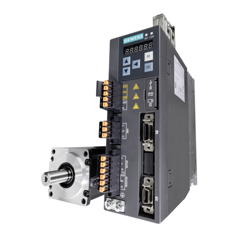
For more detailed information, please refer to the S210 Operating Instructions.
Fault Cause of fault (see 'Fault cases and remedial measures' below
Motor does not start A B
Motor starts slowly A C F
Humming sound when starting C F
Humming sound in operation A C F
High temperature rise under no-load
operation D I
High temperature rise under load A C I
High temperature rise of individual
winding sections F
Uneven running JK
Grinding sound, running noise L
Radial vibrations M N O P R
Axial vibrations O Q R
No. Fault cause Remedial measures
AOverload Reduce load
BInterruption of a phase in the supply
cable / motor winding
Check the converter and supply cables, measure the winding
resistances and insulation resistances, repair after
consultation with manufacturer
CInterrupted phase in the feeder
cable after switching on
Check the frequency converter, supply cables and the winding
resistances
DConverter output voltage too high,
frequency too low
Check the settings on the frequency converter, perform
automatic motor identication
FWinding short-circuit or phase short-
circuit in stator winding
Measure the winding resistances and insulation resistances,
repair after consultation with the manufacturer, if required,
replace the motor
I
Heat dissipation impeded by
deposits
Clean the surface of the drives and ensure that the cooling air
can ow in and out unimpeded
Cooling air inlet/outlet is blocked by
foreign bodies
Remove the reason for the blocking and ensure that the
cooling air can ow in and out unimpeded
JInsufcient shielding for motor and/
or encoder cable Check the shielding and grounding
KExcessive drive controller gain Adjust the controller
L
Rotating parts are grinding Determine cause and adjust parts
Foreign bodies inside the motor Replace the motor
Bearing damage Replace the motor
M Rotor not balanced Replace the motor
N Rotor out of true, shaft bent Consult the manufacturer
OPoor alignment Align motor set, check coupling
PCoupled machine not balanced Re-balance coupled machine
QShocks from coupled machine Check coupled machine
RFault originating from the gearbox Adjust/repair gearbox
Commissioning with web server
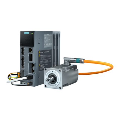
Use the web server integrated in the converter for the commissioning. The Web server integrated in the
converter supports the following browsers:
• Microsoft Internet Explorer 11
• Microsoft Edge ≥ V14
• Mozilla Firefox ≥ 48
• Google Chrome ≥ V52
Preparation for commissioning
• Mount the motor on the mechanical system. Connect the motor to the converter.
• Connect the converter to your Commissioning-PC via the Ethernet interface (X127).
• Switch the converter on.
The converter powers up and reads the motor data.
• Start the Internet-Browser for commissioning.
• Enter the IP address of the converter in the input line of your browser.
Default-IP-Address: 169.254.11.22 (Subnet-Mask: 255.255.0.0).
Note
If the RDY LED is blinking fast in yellow after the rst power up of the converter, then a power cycle is
required after an update of a motor component. Turn the 24V supply of the converter off and back on
again.
WARNING
Danger due to moving parts of the machine
During the following steps the motor will rotate. Please make sure that the motor is mounted and
connected correctly and that the connected mechanics may be moved without causing a damage or
injury.
Perform a One-Button-Tuning
For the optimization of the control parameters, perform the following procedure:
1. Select 'Commissioning'
2. Select 'Tuning'
3. Click on „Take Control“ and conrm the conrmation prompt (Orange/white bar appears).
4. Choose a Dynamic setting according to the mechanical capabilities of your machine.
5. Click on „Start tuning“.
6. Enter the permissible angle of rotation for the required measurement about which the motor and the
connected machine are permitted to turn without causing a damage to the mechanics (the angle
should at least be 60°, a greater angle leads to better results).
7. Conrm with OK and the tuning will start.
Control panel
If it is required to move the axis this can be done using the control panel. Click on the button 'Control panel'
in the footer, take over the control and enter the desired speed.
Now the axis can be moved by holding the 'Rotate Left/Right' buttons.
Diagnostic of the converter
Besides the diagnose with the Webserver troubleshooting can be done directly on the
device. The alarms and faults are shown in the display of the converter according to the
message classes dened in PROFIdrive.
Display and operational elements
The converter displays the current operating state via two LEDs.
• RDY: Status of the converter
• COM: Status of the communication
Faults can be acknowledged with the OK button.
When using an SD-Card, push it into the slot (label to the left). When parameters were
saved on the card after commissioning, an easy exchange of the converter is possible in
case of a defect. Switch the converter off to plug-in or remove the SD card.
Message number Description
1Hardware/software error
Hardware or software malfunction
2Network fault
A line supply fault has occurred (phase failure, voltage level, etc.)
3Supply voltage fault
Power supply fault (24 V) has been identied
4DC link overvoltage
The DC-link voltage is too high
5Power electronics fault
Failure in power electronics (overcurrent, overtemperature, IGBT failure,…)
6Overtemperature electronic component
Temperature of electronics exceeded the highest permissible limit
7Ground fault / inter-phase short-circuit detected
Failure in the power cables or motor windings
8Motor overload
The motor has exceeded its limits
9Communication error to PLC
Interrupted or failed network communications
10 Safety monitoring channel detected an error
A safe operation function has detected an error
11 Position actual value/speed value error
Encoder signal error detected (track signals, zero marks, absolute values…)
12 Internal (DRIVE-CLiQ) communication error
Communications between SINAMICS components is faulty or has been interrupted
13 Fault infeed
The infeed is faulty or has failed.
14 Braking controller / Braking Module error
Braking Module fault or overloaded
15 Line lter fault
The line lter exceeded temperature limits or has non-permissible state
16 External value/signal out of the range
Digital/Analog inputs error (or temperature)
17 Application / technology fault
Application or technology function has exceeded a limit (position, velocity, torque…)
18 Error in the conguration/commissioning
Error in the commissioning procedure, or the conguration of the device
19 General drive fault
Group fault
20 Auxiliary unit fault
Auxiliary unit has identied an illegal state.
SIMATIC S210 Operating Instructions
www.siemens.com/sinamics-s210
Assigning an Administrator password
In order to get full access to the converter you have to log-in as Administrator.
For the access as Administrator a password is required.
After powering up the converter a dialog to enter the Administrator password appears for 10 min.
The following mask appears only if the Administrator password has not been assigned and only for the
duration of 10 minutes after powering up the converter.
Assign an Administrator password.
Note
Note down the password and store it carefully in a secure place!
Login
After assigning the Administrator password the Log-in page is displayed.
Enter the login „ Administrator“ and the password which you have assigned in the step before.
After a successful log-in the Overview page appears.
Additional functions
Further adjustments can be made by selecting the menu item 'Parameters'.
You can also save the parameter settings and restore them later if required or you can reset the
converter to the factory defaults.
For this choose the menu item 'Backup &Restore'.
In the 'System' menu you can change passwords and enable the access to the web server via the
Pronet interface (X150).
Saving changes
In order to save the changes permanently click on the oppy disk symbol in the footer.
Messages
In the menu choose 'Diagnostics' and 'Messages' to display the Warnings and Alarms including
information concerning cause and remedy. A detailed description of the events is available in the
manual.
Safety functions
A detailed description of the Safety commissioning can be found in the S210 operation
instructions under
www.siemens.com/sinamics-s210
Underwriters Laboratories
For United States / Canadian installations (UL/cUL): The products are cULus listed under File
E355661 Vol. 3 Sec. 8.
Solid State Motor Overload Protection: 300% of motor FLA.
Suitable for use on a circuit capable of delivering not more than 65 kA rms (symmetrical), 240 V maximum.
Branch circuit protection for individual drives shall be provided by Class J fuses stated in Technical Data.
Branch circuit protection for group installation shall be provided by 30 Amps Class J fuses.
For further protective devices and SCCRs for individual drives and group installation refer to:
https://support.industry.siemens.com/cs/document/109748999
This equipment is to be installed in an enclosure that provides a pollution degree 2 (controlled) environment.
Equipment does not provide internal motor overtemperature protection. Overtemperature protection is
provided by evaluation of thermal sensor.
Use 75°C rated copper wires for all power conductors.
Additional requirements for CSA compliance:
Overvoltage Category OVC III must be ensured for all primary circuit connections of the equipment. This
may require Surge Protective Devices (SPD) to be installed on the line side of the equipment. The SPDs
shall be rated 240V (phase to phase and phase to ground) and shall provide protection for a rated impulse
withstand voltage peak of 4kV.
