manuals.online logo
Brands
  1. Home
  2. •
  3. Brands
  4. •
  5. Omron
  6. •
  7. Servo Drive
  8. •
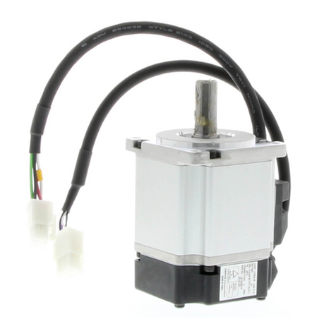
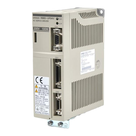
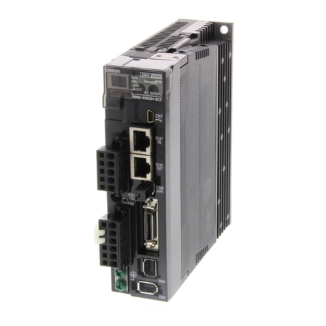
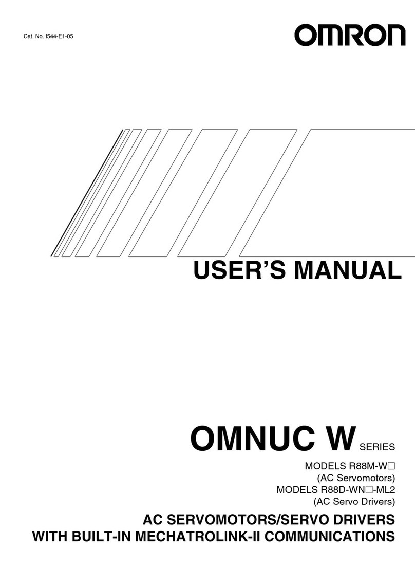
  9. Omron R88M-U03030HA User manual

Omron R88M-U03030HA User manual

Thank you for choosing this OMNUC UP-series product.
This manual provides details on the installation, wiring, troubleshooting, and maintenance of OMNUC
UP-series products along with parameter settings for the operation of the products.
General Instructions
1. Refer to Precautions first and carefully read and be sure to understand the information provided.
2. Familiarize
yourself with this manual and understand the functions and performance of the Servomotor and
Ser
-
vo Driver for proper use.
3. The
Servomotor and Servo Driver must be wired and the Parameter Unit must be operated by experts in electri
-
cal
engineering.
4. We
recommend that you add the following precautions to any instruction manuals you prepare for the system
into which the product is being installed.
SPrecautions on the dangers of high-voltage equipment.
SPrecautions
on touching the terminals of the product even after power has
been turned of
f. (These terminals
are live even with the power turned off.)
5. Do
not perform withstand voltage or other megameter tests on the product. Doing so may damage internal com
-
ponents.
6. Servomotors
and Servo Drivers have a finite service life. Be sure to keep replacement products on hand and to
consider the operating environment and other conditions affecting the service life.
7. Do
not set any parameter not described in this manual, otherwise the Servomotor or Servo Driver may malfunc
-
tion. Contact your OMRON representatives if you have any inquiry.
8. The
functions and specifications dif
fer
for the various models, as shown below
. Be sure to check which models
are being used before proceeding.
SHA/LA/V/W AC Servo Drivers: R88D-UPjjHA, R88D-UPjjLA, R88D-UPjjV, and R88D-UPjjW
SH/L AC Servo Drivers: R88D-UPjjH and R88D-UPjjL
NOTICE
Before using the product under the following conditions, consult your OMRON representatives, make
sure
that the ratings and performance characteristics of the product are good enough for the systems,
machines,
or equipment, and be sure to provide the systems, machines, or equipment with double safety
mechanisms.
1. Conditions not described in the manual.
2. The
application of the product to nuclear control systems, railroad systems, aviation systems, vehicles, com
-
bustion systems, medical equipment, amusement machines, or safety equipment.
3. The
application of
the product to systems, machines, or equipment that may have a serious influence on human
life and property if they are used improperly.
Items to Check After Unpacking
Check the following items after removing the product from the package:
SHas the correct product been delivered (i.e., the correct model number and specifications)?
SHas the product been damaged in shipping?
The product is provided with this manual. No connectors or mounting screws are provided.
SMake
sure that actual users of this product will read this manual thoroughly and handle and operate the product with care.
SRetain this manual for future reference.
SThis
manual describes the specifications and functions of the product and relations with other products. Assume that noth
-
ing described in this manual is possible.
SSpecifications and functions may change without notice to improve product performance.
SForward
and reverse rotation of AC Servomotors described in this
manual are defined as looking at the end of the output
shaft of the motor as follows: counterclockwise rotation (CCW) is forward and clockwise rotation (CW) is reverse.

USER’S MANUAL
MODELS R88M-Uj
(AC Servomotors)
MODELS R88D-UPj
(AC Servo Drivers)
AC SERVOMOTORS/DRIVERS (30 to 750-W Pulse-train Inputs)
OMNUC USERIES
1
No. 6182
OMRON Corporation
Please read and understand this manual before using the product. Please consult your OMRON
representative if you have any questions or comments.
Read and Understand this Manual
Warranty and Limitations of Liability
WARRANTY
OMRON's exclusive warranty is that the products are free from defects in materials and workmanship for a
period of one year (or other period if specified) from date of sale by OMRON.
OMRON MAKES NO WARRANTY OR REPRESENTATION, EXPRESS OR IMPLIED, REGARDING NON-
INFRINGEMENT, MERCHANTABILITY, OR FITNESS FOR PARTICULAR PURPOSE OF THE
PRODUCTS. ANY BUYER OR USER ACKNOWLEDGES THAT THE BUYER OR USER ALONE HAS
DETERMINED THAT THE PRODUCTS WILL SUITABLY MEET THE REQUIREMENTS OF THEIR
INTENDED USE. OMRON DISCLAIMS ALL OTHER WARRANTIES, EXPRESS OR IMPLIED.
LIMITATIONS OF LIABILITY
OMRON SHALL NOT BE RESPONSIBLE FOR SPECIAL, INDIRECT, OR CONSEQUENTIAL DAMAGES,
LOSS OF PROFITS OR COMMERCIAL LOSS IN ANY WAY CONNECTED WITH THE PRODUCTS,
WHETHER SUCH CLAIM IS BASED ON CONTRACT, WARRANTY, NEGLIGENCE, OR STRICT
LIABILITY.
In no event shall the responsibility of OMRON for any act exceed the individual price of the product on which
liability is asserted.
IN NO EVENT SHALL OMRON BE RESPONSIBLE FOR WARRANTY, REPAIR, OR OTHER CLAIMS
REGARDING THE PRODUCTS UNLESS OMRON'S ANALYSIS CONFIRMS THAT THE PRODUCTS
WERE PROPERLY HANDLED, STORED, INSTALLED, AND MAINTAINED AND NOT SUBJECT TO
CONTAMINATION, ABUSE, MISUSE, OR INAPPROPRIATE MODIFICATION OR REPAIR.
2
No. 6182
Application Considerations
SUITABILITY FOR USE
OMRON shall not be responsible for conformity with any standards, codes, or regulations that apply to the
combination of products in the customer's application or use of the products.
At the customer's request, OMRON will provide applicable third party certification documents identifying
ratings and limitations of use that apply to the products. This information by itself is not sufficient for a
complete determination of the suitability of the products in combination with the end product, machine,
system, or other application or use.
The following are some examples of applications for which particular attention must be given. This is not
intended to be an exhaustive list of all possible uses of the products, nor is it intended to imply that the uses
listed may be suitable for the products:
• Outdoor use, uses involving potential chemical contamination or electrical interference, or conditions or
uses not described in this manual.
• Nuclear energy control systems, combustion systems, railroad systems, aviation systems, medical
equipment, amusement machines, vehicles, safety equipment, and installations subject to separate
industry or government regulations.
• Systems, machines, and equipment that could present a risk to life or property.
Please know and observe all prohibitions of use applicable to the products.
NEVER USE THE PRODUCTS FOR AN APPLICATION INVOLVING SERIOUS RISK TO LIFE OR
PROPERTY WITHOUT ENSURING THAT THE SYSTEM AS A WHOLE HAS BEEN DESIGNED TO
ADDRESS THE RISKS, AND THAT THE OMRON PRODUCTS ARE PROPERLY RATED AND INSTALLED
FOR THE INTENDED USE WITHIN THE OVERALL EQUIPMENT OR SYSTEM.
PROGRAMMABLE PRODUCTS
OMRON shall not be responsible for the user's programming of a programmable product, or any
consequence thereof.
No. 6182
3
Disclaimers
CHANGE IN SPECIFICATIONS
Product specifications and accessories may be changed at any time based on improvements and other
reasons.
It is our practice to change model numbers when published ratings or features are changed, or when
significant construction changes are made. However, some specifications of the products may be changed
without any notice. When in doubt, special model numbers may be assigned to fix or establish key
specifications for your application on your request. Please consult with your OMRON representative at any
time to confirm actual specifications of purchased products.
DIMENSIONS AND WEIGHTS
Dimensions and weights are nominal and are not to be used for manufacturing purposes, even when
tolerances are shown.
PERFORMANCE DATA
Performance data given in this manual is provided as a guide for the user in determining suitability and does
not constitute a warranty. It may represent the result of OMRON's test conditions, and the users must
correlate it to actual application requirements. Actual performance is subject to the OMRON Warranty and
Limitations of Liability.
ERRORS AND OMISSIONS
The information in this manual has been carefully checked and is believed to be accurate; however, no
responsibility is assumed for clerical, typographical, or proofreading errors, or omissions.
!
!
!
Notice:
OMRON products are manufactured for use according to proper procedures by a qualified
operator and only for the purposes described in this manual.
The following conventions are used to indicate and classify precautions in this manual. Al-
ways heed the information provided with them. Failure to heed precautions can result in inju-
ry to people or damage to property.
DANGER Indicates
an imminently hazardous situation which, if not avoided, will
result in death
or serious injury.
WARNING Indicates
a potentially hazardous situation which, if not avoided, could result in death
or serious injury.
Caution Indicates
a potentially hazardous situation which, if not avoided, may result in minor
or moderate injury, or property damage.
OMRON Product References
All OMRON products are capitalized in this manual. The word “Unit” is also capitalized when
it refers to an OMRON product, regardless of whether or not it appears in the proper name
of the product.
The abbreviation “Ch,” which appears in some displays and on some OMRON products, of-
ten means “word” and is abbreviated “Wd” in documentation in this sense.
The abbreviation “PC” means Programmable Controller and is not used as an abbreviation
for anything else.
Visual Aids
The following headings appear in the left column of the manual to help you locate different
types of information.
Note Indicates information of particular interest for efficient and convenient operation of the product.
OMRON, 1994
All rights reserved. No part of this publication may be reproduced, stored in a retrieval sys-
tem, or transmitted, in any form, or by any means, mechanical, electronic, photocopying,
recording, or otherwise, without the prior written permission of OMRON.
No patent liability is assumed with respect to the use of the information contained herein.
Moreover, because OMRON is constantly striving to improve its high-quality products, the
information contained in this manual is subject to change without notice. Every precaution
has been taken in the preparation of this manual. Nevertheless, OMRON assumes no re-
sponsibility for errors or omissions. Neither is any liability assumed for damages resulting
from the use of the information contained in this publication.
!
!
!
!
!
!
!
!
!
!
General Warnings
Observe the following warnings when using the OMNUC Servomotor and Servo Driver.
This manual may include illustrations of the product with protective covers removed in order
to describe the components of the product in detail. Make sure that these protective covers
are on the product before use.
Consult your OMRON representative when using the product after a long period of storage.
WARNING Always
connect the frame ground terminals of the Servo Driver and the Servomotor
to
a class-3 ground (to 100
Ω
or less). Not connecting to
a class-3 ground may result
in electric shock.
WARNING Do not touch the inside of the Servo Driver. Doing so may result in electric shock.
WARNING Do
not remove the front cover
, terminal covers, cables, Parameter Units, or optional
items while the power is being supplied. Doing so may result in electric shock.
WARNING Operation,
maintenance, or inspection must be performed by authorized personnel.
Not doing so may result in electric shock or injury.
WARNING Wiring
or inspection must be performed at least
5 minutes after turning of
f the power
supply. Doing so may result in electric shock.
WARNING Do
not damage, press, or put excessive stress or heavy
objects on the cables. Doing
so may result in electric shock.
WARNING Do not touch the rotating parts of the Servomotor under operation. Doing so may
result in injury.
WARNING Do
not modify the product. Doing so may result in injury or damage to the
product.
Caution Use the Servomotors and Servo Drivers in a specified combination.
Doing so may
result in fire or damage to the products.
Caution Do
not store or install in the following places. Doing so may result in fire or damage to
the Product.
SLocations subject to direct sunlight.
SLocations subject to temperatures or humidity outside the range specified in the
specifications.
SLocations
subject to condensation as the result of severe changes in
temperature.
SLocations subject to corrosive or flammable gases.
SLocations subject to dust (especially iron dust) or salts.
SLocations subject to shock or vibration.
SLocations subject to exposure to water, oil, or chemicals.
!
!
!
!
!
!
!
!
!
!
!
!
!
Caution Do
not touch the Servo Driver radiator or Servomotor while the power is being sup
-
plied or soon after the power is turned of
f. Doing so may
result in a skin burn due to
the hot surface.
Storage and Transportation Precautions
Caution Do not hold by the cables or motor shaft while transporting the product. Doing so
may result in injury or malfunction.
Caution Do
not place any load exceeding the figure indicated on the product.
Doing so may
result in injury or malfunction.
Caution Use
the motor eye-bolts only for transporting the
Motor
. Using them for transporting
the machinery may result in injury or malfunction.
Installation and Wiring Precautions
Caution Do
not step on or place a heavy object on the
product. Doing so may result in injury
.
Caution Do
not cover the inlet or outlet ports and prevent any foreign objects from entering
the product. Doing so may result in fire.
Caution Be
sure to install the product in the correct direction. Not doing so may result in mal
-
function.
Caution Provide
the specified clearances between the Servo Driver and the
control panel or
with other devices. Not doing so may result in fire or malfunction.
Caution Do not apply any strong impact. Doing so may result in malfunction.
Caution Be sure to wire correctly and securely. Not doing so may result in motor runaway,
injury, or malfunction.
Caution Be
sure that all
the mounting screws, terminal screws, and cable connector screws
are tightened to the torque specified in the relevant manuals. Incorrect tightening
torque may result in malfunction.
Caution Use
crimp terminals for wiring. Do not connect bare stranded wires directly to termi
-
nals. Connection of bare stranded wires may result in burning.
Caution Always use the power supply voltage specified in the User’s Manual. An incorrect
voltage may result in malfunction or burning.
!
!
!
!
!
!
!
!
!
!
!
Caution Take
appropriate
measures to ensure that the specified power with the rated voltage
and
frequency is supplied.
Be particularly careful in places where the power supply
is unstable. An incorrect power supply may result in malfunction.
Caution Install
external breakers and take other safety measures against short-circuiting in
external wiring. Insufficient safety measures against short-circuiting may result in
burning.
Caution Provide an appropriate stopping device on the machine side to secure safety. (A
holding
brake is not a stopping device
for securing safety
.) Not doing so may result in
injury.
Caution Provide
an external emergency stopping device that allows an instantaneous stop
of
operation and power interruption. Not doing so may result in injury.
Caution Take
appropriate and suf
ficient
countermeasures when installing systems in the fol
-
lowing locations:
SLocations subject to static electricity or other forms of noise.
SLocations subject to strong electromagnetic fields and magnetic fields.
SLocations subject to possible exposure to radioactivity.
SLocations close to power supplies.
Operation and Adjustment Precautions
Caution Check
the newly
set parameters for proper execution before actually running them.
Not doing so may result in equipment damage.
Caution Do not make any extreme adjustments or setting changes. Doing so may result in
unstable operation and injury.
Caution Separate the Servomotor from the machine, check for proper operation, and then
connect to the machine. Not doing so may cause injury.
Caution When an alarm occurs, remove the cause, reset the alarm after confirming safety,
and then resume operation. Not doing so may result in injury.
Caution Do not come close to the machine immediately after resetting momentary power
interruption
to avoid an unexpected restart. (T
ake appropriate measures to secure
safety against an unexpected restart.) Doing so may result in injury.
Caution Do
not use the built-in brake
of the Servomotor for ordinary braking. Doing so may
result in malfunction.
!
!
Maintenance and Inspection Precautions
WARNING Do
not attempt to disassemble, repair
, or modify any Units. Any attempt to do so may
result in malfunction, fire, or electric shock.
Caution Resume operation only after transferring to the new Unit the contents of the data
required for operation. Not doing so may result in an unexpected operation.
Warning Labels
Warning labels are pasted on the product as shown in the following illustration. Be sure to
follow the instructions given there.
Warning
labels
Warning Labels for Non-conforming Models
Warning
label 1
W
arning label 2
Warning Labels for Models Conforming to EC Directives
Warning
label 1
W
arning label 2
VISUAL INDEX
For users who wish to operate soon.
-The
following portions of
this manual provide the minimum information required for operation.
Be
sure you fully understand at least the
information in these portions before attempting opera
-
tion.
Chapter
2 System Design and Installation, and sections
3-1,
3-2,
3-3,
3-4,
3-5, and
3-6 of Chap
-
ter 3 Operation.
Instructions for jog operation using a Parameter Unit are provided in 3-6.
OMNUC U is a series of fully
software-controlled AC servo
drivers
built on advanced
OM
-
RON software servo technol-
ogy. It provides high perfor-
mance, a sensitive man-ma-
chine
interface, and economy
.
SYSMAC CS1/C/CV
Programmable Controller
Pulse input
Controller Connecting Cable
Chapter 5: 5-3-1
Setting Functions
-Setting User Parameters: Section 3-5-1
-Internally Set Speed Control: Section 3-5-3
-Electronic Gears: Section 3-5-4
-Encoder Dividing: Section 3-5-5
-Bias: Section 3-5-6
-Torque Control: Section 3-5-7
-Brake Interlock: Section 3-5-8
Adjustments and Troubleshooting
-Adjustments: Section 3-7
-Displays: Section 4-1
-Monitor Outputs: Section 4-2
-Protections and Diagnostics: Section 4-3
-Troubleshooting: Section 4-4
Position Control Unit
C200HW-NC113
C200HW-NC213
C200HW-NC413
C200H-NC112
C200H-NC211
C500-NC113
C500-NC211
OMNUC U Series
OMNUC U-series AC Servo Driver
I/O Operations
Chapter 5: 5-1-3
Cable Specifications
Chapter 5: 5-3-2, 5-3-3
Power
signals
Encoder
signals
Motor Specifications
Chapter 5: 5-2
OMNUC U-series
AC Servomotor
Operation Method
Chapter 3: 3-3, 3-4, 3-5
Parameter Units
Table of Contents
Chapter 1. Introduction .
. . . . . . . . . . . . . . . . . . . . . . . . . . . . . . . . . . . .
1-1 Features . . . . . . . . . . . . . . . . . . . . . . . . . . . . . . . . . . . . . . . . . . . . . . . . . . . . . . . . . . . . . . . . . . .
1-2 System Configuration . . . . . . . . . . . . . . . . . . . . . . . . . . . . . . . . . . . . . . . . . . . . . . . . . . . . . . . .
1-3 Servo Driver Nomenclature . . . . . . . . . . . . . . . . . . . . . . . . . . . . . . . . . . . . . . . . . . . . . . . . . . . .
1-4 Applicable Standards and Models . . . . . . . . . . . . . . . . . . . . . . . . . . . . . . . . . . . . . . . . . . . . . . .
1-4-1 UL/cUL Standards . . . . . . . . . . . . . . . . . . . . . . . . . . . . . . . . . . . . . . . . . . . . . . . . . . . .
1-4-2 EC Directives . . . . . . . . . . . . . . . . . . . . . . . . . . . . . . . . . . . . . . . . . . . . . . . . . . . . . . . .
Chapter
2. System Design and Installation
.
. . . . . . . . . . . . . . . . . . . . .
2-1 Installation . . . . . . . . . . . . . . . . . . . . . . . . . . . . . . . . . . . . . . . . . . . . . . . . . . . . . . . . . . . . . . . . .
2-1-1 External Dimensions (Unit: mm) . . . . . . . . . . . . . . . . . . . . . . . . . . . . . . . . . . . . . . . . .
2-1-2 Installation Conditions . . . . . . . . . . . . . . . . . . . . . . . . . . . . . . . . . . . . . . . . . . . . . . . . .
2-2 Wiring Products Conforming to UL/cUL
and Wiring Products Not Conforming to Any Standards . . . . . . . . . . . . . . . . . . . . . . . . . . . . .
2-2-1 Connecting OMRON Servo Controllers . . . . . . . . . . . . . . . . . . . . . . . . . . . . . . . . . . . .
2-2-2 Connector-Terminal Conversion Unit . . . . . . . . . . . . . . . . . . . . . . . . . . . . . . . . . . . . .
2-2-3 Wiring Servo Drivers . . . . . . . . . . . . . . . . . . . . . . . . . . . . . . . . . . . . . . . . . . . . . . . . . .
2-2-4 Wiring for Noise Resistance . . . . . . . . . . . . . . . . . . . . . . . . . . . . . . . . . . . . . . . . . . . . .
2-2-5 Peripheral Device Connection Examples . . . . . . . . . . . . . . . . . . . . . . . . . . . . . . . . . . .
2-3 Wiring Products Conforming to EC Directives . . . . . . . . . . . . . . . . . . . . . . . . . . . . . . . . . . . . .
2-3-1 Connecting Servo Controllers . . . . . . . . . . . . . . . . . . . . . . . . . . . . . . . . . . . . . . . . . . . .
2-3-2 Wiring Servo Drivers . . . . . . . . . . . . . . . . . . . . . . . . . . . . . . . . . . . . . . . . . . . . . . . . . .
2-3-3 Wiring Products Conforming to EMC Directives . . . . . . . . . . . . . . . . . . . . . . . . . . . .
2-3-4 Peripheral Device Connection Examples . . . . . . . . . . . . . . . . . . . . . . . . . . . . . . . . . . .
Chapter
3. Operation
.
. . . . . . . . . . . . . . . . . . . . . . . . . . . . . . . . . . . . . .
3-1 Operational Procedure . . . . . . . . . . . . . . . . . . . . . . . . . . . . . . . . . . . . . . . . . . . . . . . . . . . . . . . .
3-2 Turning On Power and Checking Displays . . . . . . . . . . . . . . . . . . . . . . . . . . . . . . . . . . . . . . . .
3-2-1 Items to Check Before Turning On Power . . . . . . . . . . . . . . . . . . . . . . . . . . . . . . . . . .
3-2-2 Turning On Power and Confirming the Display . . . . . . . . . . . . . . . . . . . . . . . . . . . . .
3-3 Using Parameter Units . . . . . . . . . . . . . . . . . . . . . . . . . . . . . . . . . . . . . . . . . . . . . . . . . . . . . . . .
3-3-1 Parameter Unit Keys and Functions . . . . . . . . . . . . . . . . . . . . . . . . . . . . . . . . . . . . . . .
3-3-2 Modes and Changing Modes . . . . . . . . . . . . . . . . . . . . . . . . . . . . . . . . . . . . . . . . . . . .
3-3-3 Mode Changes and Display Contents . . . . . . . . . . . . . . . . . . . . . . . . . . . . . . . . . . . . . .
3-4 Initial Settings: Setup Parameters . . . . . . . . . . . . . . . . . . . . . . . . . . . . . . . . . . . . . . . . . . . . . . .
3-4-1 Setting and Checking Setup Parameters (Cn-01, 02) . . . . . . . . . . . . . . . . . . . . . . . . . .
3-4-2 Setup Parameter Contents . . . . . . . . . . . . . . . . . . . . . . . . . . . . . . . . . . . . . . . . . . . . . . .
3-4-3 Important Setup Parameters (Cn-01 and Cn-02) . . . . . . . . . . . . . . . . . . . . . . . . . . . . .
3-5 Setting Functions: User Parameters . . . . . . . . . . . . . . . . . . . . . . . . . . . . . . . . . . . . . . . . . . . . . .
3-5-1 Setting and Checking User Parameters (Cn-04 to 29) . . . . . . . . . . . . . . . . . . . . . . . . .
3-5-2 User Parameter Chart . . . . . . . . . . . . . . . . . . . . . . . . . . . . . . . . . . . . . . . . . . . . . . . . . .
3-5-3 Internal Speed Control Settings . . . . . . . . . . . . . . . . . . . . . . . . . . . . . . . . . . . . . . . . . .
3-5-4 Electronic Gear Function: Position Control . . . . . . . . . . . . . . . . . . . . . . . . . . . . . . . . .
3-5-5 Encoder Dividing Function . . . . . . . . . . . . . . . . . . . . . . . . . . . . . . . . . . . . . . . . . . . . . .
3-5-6 Bias Function: Position Control . . . . . . . . . . . . . . . . . . . . . . . . . . . . . . . . . . . . . . . . . .
3-5-7 Torque Limit Function . . . . . . . . . . . . . . . . . . . . . . . . . . . . . . . . . . . . . . . . . . . . . . . . .
3-5-8 Brake Interlock (For Motors with Brakes) . . . . . . . . . . . . . . . . . . . . . . . . . . . . . . . . . .
3-6 Trial Operation . . . . . . . . . . . . . . . . . . . . . . . . . . . . . . . . . . . . . . . . . . . . . . . . . . . . . . . . . . . . . .
3-6-1 Preparations for Trial Operation . . . . . . . . . . . . . . . . . . . . . . . . . . . . . . . . . . . . . . . . . .
3-6-2 Jog Operations . . . . . . . . . . . . . . . . . . . . . . . . . . . . . . . . . . . . . . . . . . . . . . . . . . . . . . .
Table of Contents
3-7 Making Adjustments . . . . . . . . . . . . . . . . . . . . . . . . . . . . . . . . . . . . . . . . . . . . . . . . . . . . . . . . .
3-7-1 Auto-tuning . . . . . . . . . . . . . . . . . . . . . . . . . . . . . . . . . . . . . . . . . . . . . . . . . . . . . . . . . .
3-7-2 Manually Adjusting Gain . . . . . . . . . . . . . . . . . . . . . . . . . . . . . . . . . . . . . . . . . . . . . . .
3-8 Regenerative Energy Absorption . . . . . . . . . . . . . . . . . . . . . . . . . . . . . . . . . . . . . . . . . . . . . . . .
3-8-1 Calculating Regenerative Energy . . . . . . . . . . . . . . . . . . . . . . . . . . . . . . . . . . . . . . . . .
3-8-2 Servo Driver Absorbable Regenerative Energy . . . . . . . . . . . . . . . . . . . . . . . . . . . . . .
3-8-3 Absorption of Regenerative Energy with the External Regeneration Resistor
(Models Conforming to UL/cUL Standards
and Models Not Conforming to Any Standards) . . . . . . . . . . . . . . . . . . . . . . . . . . . . .
3-8-4 Processing Regenerative Energy with Multiple Axes
(Models Conforming to EC Directives) . . . . . . . . . . . . . . . . . . . . . . . . . . . . . . . . . . . .
Chapter
4. Application
.
. . . . . . . . . . . . . . . . . . . . . . . . . . . . . . . . . . . . .
4-1 Using Displays . . . . . . . . . . . . . . . . . . . . . . . . . . . . . . . . . . . . . . . . . . . . . . . . . . . . . . . . . . . . . .
4-1-1 Display Functions . . . . . . . . . . . . . . . . . . . . . . . . . . . . . . . . . . . . . . . . . . . . . . . . . . . . .
4-1-2 Status Display Mode . . . . . . . . . . . . . . . . . . . . . . . . . . . . . . . . . . . . . . . . . . . . . . . . . . .
4-1-3 Monitor Mode (Un-) . . . . . . . . . . . . . . . . . . . . . . . . . . . . . . . . . . . . . . . . . . . . . . . . . . .
4-1-4 Checking Servomotor Parameters (Cn-00 Set to 04) . . . . . . . . . . . . . . . . . . . . . . . . . .
4-2 Using the Monitor Output . . . . . . . . . . . . . . . . . . . . . . . . . . . . . . . . . . . . . . . . . . . . . . . . . . . . .
4-3 Protective and Diagnostic Functions . . . . . . . . . . . . . . . . . . . . . . . . . . . . . . . . . . . . . . . . . . . . .
4-3-1 Alarm Displays and Alarm Code Outputs . . . . . . . . . . . . . . . . . . . . . . . . . . . . . . . . . .
4-3-2 Alarm Output . . . . . . . . . . . . . . . . . . . . . . . . . . . . . . . . . . . . . . . . . . . . . . . . . . . . . . . .
4-3-3 Overload Characteristics (Electron Thermal Characteristics) . . . . . . . . . . . . . . . . . . .
4-3-4 Alarm History Display Mode . . . . . . . . . . . . . . . . . . . . . . . . . . . . . . . . . . . . . . . . . . . .
4-4 Troubleshooting . . . . . . . . . . . . . . . . . . . . . . . . . . . . . . . . . . . . . . . . . . . . . . . . . . . . . . . . . . . . .
4-5 Periodic Maintenance . . . . . . . . . . . . . . . . . . . . . . . . . . . . . . . . . . . . . . . . . . . . . . . . . . . . . . . .
Chapter
5. Specifications
.
. . . . . . . . . . . . . . . . . . . . . . . . . . . . . . . . . . .
5-1 Servo Driver Specifications . . . . . . . . . . . . . . . . . . . . . . . . . . . . . . . . . . . . . . . . . . . . . . . . . . . .
5-1-1 General Specifications . . . . . . . . . . . . . . . . . . . . . . . . . . . . . . . . . . . . . . . . . . . . . . . . .
5-1-2 Performance Specifications . . . . . . . . . . . . . . . . . . . . . . . . . . . . . . . . . . . . . . . . . . . . .
5-1-3 I/O Specifications . . . . . . . . . . . . . . . . . . . . . . . . . . . . . . . . . . . . . . . . . . . . . . . . . . . . .
5-1-4 Explanation of User Parameters . . . . . . . . . . . . . . . . . . . . . . . . . . . . . . . . . . . . . . . . . .
5-2 Servomotor Specifications . . . . . . . . . . . . . . . . . . . . . . . . . . . . . . . . . . . . . . . . . . . . . . . . . . . . .
5-2-1 General Specifications . . . . . . . . . . . . . . . . . . . . . . . . . . . . . . . . . . . . . . . . . . . . . . . . .
5-2-2 Performance Specifications . . . . . . . . . . . . . . . . . . . . . . . . . . . . . . . . . . . . . . . . . . . . .
5-2-3 Torque and Rotational Speed Characteristics . . . . . . . . . . . . . . . . . . . . . . . . . . . . . . . .
5-2-4 Allowable Loads on Servomotor Shafts . . . . . . . . . . . . . . . . . . . . . . . . . . . . . . . . . . . .
5-2-5 Encoder Specifications . . . . . . . . . . . . . . . . . . . . . . . . . . . . . . . . . . . . . . . . . . . . . . . . .
5-3 Cable Specifications . . . . . . . . . . . . . . . . . . . . . . . . . . . . . . . . . . . . . . . . . . . . . . . . . . . . . . . . .
5-3-1 Controller Connecting Cables . . . . . . . . . . . . . . . . . . . . . . . . . . . . . . . . . . . . . . . . . . .
5-3-2 Encoder Cables . . . . . . . . . . . . . . . . . . . . . . . . . . . . . . . . . . . . . . . . . . . . . . . . . . . . . . .
5-3-3 Power Cable . . . . . . . . . . . . . . . . . . . . . . . . . . . . . . . . . . . . . . . . . . . . . . . . . . . . . . . . .
5-4 Parameter Unit Specifications . . . . . . . . . . . . . . . . . . . . . . . . . . . . . . . . . . . . . . . . . . . . . . . . . .
5-5 Regeneration Unit Specifications . . . . . . . . . . . . . . . . . . . . . . . . . . . . . . . . . . . . . . . . . . . . . . .
5-6 Front-surface Mounting Bracket Specifications . . . . . . . . . . . . . . . . . . . . . . . . . . . . . . . . . . . .
Chapter
6. Supplementary Materials
.
. . . . . . . . . . . . . . . . . . . . . . . . .
6-1 Connection Examples . . . . . . . . . . . . . . . . . . . . . . . . . . . . . . . . . . . . . . . . . . . . . . . . . . . . . . . .
6-2 Servo Connector Terminal Connection Unit . . . . . . . . . . . . . . . . . . . . . . . . . . . . . . . . . . . . . . .
6-3 OMNUC U-series Standard Models . . . . . . . . . . . . . . . . . . . . . . . . . . . . . . . . . . . . . . . . . . . . .
6-4 Parameter Setting Forms . . . . . . . . . . . . . . . . . . . . . . . . . . . . . . . . . . . . . . . . . . . . . . . . . . . . . .
Chapter 1
Introduction
1-1 Features
1-2 System Configuration
1-3 Servo Driver Nomenclature
1-4 Applicable Standards and Models
1
1-2
1-1 Features
OMNUC
AC Servo Drivers control the power supplied to AC Servomotors with pulse-train input signals
and perform precision position control. There are 7 types of AC Servomotors: 30-W, 50-W, 100-W,
200-W, 300-W, 400-W, and 750-W.
HMotor Output Capacity
AC Servomotors with the following output capacities are available.
SFor 200/230-VAC (170 to 253 V) single-phase, 50/60-Hz Input
30 W, 50 W, 100 W, 200 W, 400 W, and 750 W
SFor 100/115-VAC (85 to 127 V) single-phase, 50/60-Hz Input
30 W, 50 W, 100 W, 200 W, and 300 W
The Servomotors also come with and without brakes, and with and without keys on the straight
shaft. Servomotors that conform to EC Directives, however, are available only with keys on the
shaft.
HModels Conforming to UL/cUL Standards Available (UL/cUL Markings)
AC
Servomotors and Servo Drivers that conform to UL/cUL Standards are now available. Their
per
-
formance,
functionality
, and appearance are the same as the conventional U-series (HA/LA) mod
-
els. They are useful for obtaining approvals required for specific applications.
Models
conforming to UL/cUL Standards have the same
product names as conventional U-series
(HA/LA)
models. As shown in the following table, they are distinguished by
the manufacturing date.
Model Manufacturing date Type Remarks
Models not conforming to
any standards Before April 1998
H/L, HA/LA
Production of H/L models
discontinued.
Models conforming to
UL/cUL Standards After May 1998 HA/LA UL/cUL markings are
attached to products.
HEC Directives (CE Markings)
AC Servomotors and Servo Drivers that conform to EC low-voltage and EMC directives are now
available.
These provide the same performance and functions as the rest of the
U Series (HA/LA),
and will aid in obtaining specifications.
HControl Functions
Any one of the following 4 control modes can be selected in the parameter settings.
SPosition Control (Factory Setting)
Controls
the position and speed of the Servomotor very precisely with pulse-train input signals.
Any one of the following 3 pulse trains can be selected: forward/reverse pulses, feed pulses/
directional signals, or 90_differential phase (A/B phases) signals.
SPosition Control with Pulse Stop Input Enabled (HA/LA/V/W Models)
Turning
ON the Pulse Stop Input (IPG) prevents the control signals from being read by the
Unit
during position control.
Introduction Chapter 1
1-3
SInternal Speed Control Settings
The
speed of the motor is controlled with the three speeds (No. 1, No. 2, and No. 3 internal speed
settings) set in the parameters. This mode is effective for simple position control or speed-
switching operation.
SInternal Speed Control Setting + Position Control (HA/LA/V/W Models)
Speed
control can be performed with the internal speed settings and position control can be per
-
formed with pulse-train inputs.
HAuto-tuning
The
gain can be adjusted automatically when the responsiveness has been selected to match the
rigidity of the mechanical system. The auto-tuning feature automatically finds the optimum adjust
-
ment to match the load, with no need for difficult operations.
HMonitor
Displays the driver’s operating status on the Parameter Unit.
The following items can be monitored: speed feedback, speed commands, torque commands,
number of pulses from the U-phase edge, electrical angle, internal status (bit display), command
pulse’s speed, position deviation, and the input pulse counter.
HJog Operation
Forward/Reverse
motor operation can be controlled from the Parameter Unit. Rotational speed can
be set in the parameters.
HElectronic Gear Function (Position Control)
The
number of pulses used to rotate the motor is calculated by multiplying the number of command
pulses by the electronic gear ratio. This function is useful in the following kinds of cases.
SWhen
you want to finely adjust the position and speed of two lines that need to be synchronized
SWhen
you want to increase the control pulse frequency of a controller with a low pulse frequency
SWhen you want to set the movement/pulse to a certain amount, such as 0.01 mm/pulse
The
electronic gear ratio is set with parameters G1 and G2 (G1=numerator and G2=denominator).
The
setting range for parameters G1 and G2 is 1 to 65,535. The setting range for the gear ratio is
0.01 to 100, i.e., 0.01 ≤G1/G2 ≤100.
HEncoder Resolution Function
This
function allows the encoder
signal output from the driver to be set anywhere from 16 to 2,048
pulses/revolution.
HSoftware Start Function (Internal Speed Control Settings)
This
function causes the motor to be started/stopped in the preset acceleration/deceleration times,
allowing
a
simple position control system to be constructed without a Positioner or Host Controller
.
The acceleration and deceleration times are set separately, and the setting range is 0 to 10 s for
each.
Introduction Chapter 1
1-4
HPulse Smoothing Function (Position Control)
Even
high-frequency commands
can be executed smoothly by including acceleration/deceleration
in the command pulses. The same setting is used for
both
the acceleration and deceleration times,
and the setting range is 0 to 64 ms.
HReverse Mode
Forward/Reverse
commands can be switched
in the parameters, without changing the wiring to the
motor or encoder.
HBrake Interlock Output
Outputs
a timing signal interlocked with the motor
’
s ON/OFF status and rotational speed. The hold
-
ing brake of a motor with a brake can be operated reliably.
HOvertravel Sequence
An
overtravel sequence compatible with the system can be selected. There are three deceleration
methods
available: dynamic brake deceleration, free-run deceleration, and emergency-stop torque
deceleration (parameter setting).
HFeed-forward and Bias Functions (Position Control)
These functions reduce the position control time.
SFeed-forward Function
Reduces
the position control time by reducing the number of pulses accumulated in the
deviation
counter.
SBias Function
Reduces
the position control time by adding the bias revolutions to
the speed control when the
deviation counter value exceeds the position completion range.
HComputer Monitor Software (HA/LA/V/W Models)
The special Servo Driver Communications Software allows parameter setting, speed and current
monitoring,
I/O monitoring, auto-tuning, and jog operations to be performed from
a personal com
-
puter.
It is also possible to perform multiple-axis communications that set the parameters and moni
-
tor the operation of several drivers. Refer to the
Computer Monitor Software Instruction Manual
(I513)
for OMNUC U-series Servo Drivers for more details.
Introduction Chapter 1
1-5
1-2 System Configuration
Parameter Units
OMNUC U-series
AC Servo Driver
OMNUC U-series
AC Servomotor
SYSMAC CS1/C/CV
Programmable Controller
C200HW-NC113
C200HW-NC213
C200HW-NC413
C200H-NC112
C200H-NC211
C500-NC113
C500-NC211
Position Control Unit
Introduction Chapter 1

This manual suits for next models

130

Other Omron Servo Drive manuals

Omron R88L-EA-AF User manual

Omron

Omron R88L-EA-AF User manual

Omron R88D-KTA5L User manual

Omron

Omron R88D-KTA5L User manual

Omron R88M-1L Series User guide

Omron

Omron R88M-1L Series User guide

Omron R88M-K Series User manual

Omron

Omron R88M-K Series User manual

Omron R88M-W60010T User manual

Omron

Omron R88M-W60010T User manual

Omron R88M-K Series User manual

Omron

Omron R88M-K Series User manual

Omron R88D-KN ML2 Sries User manual

Omron

Omron R88D-KN ML2 Sries User manual

Omron OMNUC G Series User manual

Omron

Omron OMNUC G Series User manual

Omron sysmac 1S Series User guide

Omron

Omron sysmac 1S Series User guide

Omron OMNUC U Series Quick start guide

Omron

Omron OMNUC U Series Quick start guide

Omron OMNUC W Series User manual

Omron

Omron OMNUC W Series User manual

Omron SMARTSTEP R7M-A Series User manual

Omron

Omron SMARTSTEP R7M-A Series User manual

Omron CK M-CPU1 1 Series User guide

Omron

Omron CK M-CPU1 1 Series User guide

Omron JUNMA Series User manual

Omron

Omron JUNMA Series User manual

Omron OMNUC W Series User manual

Omron

Omron OMNUC W Series User manual

Omron OMNUC U Series User manual

Omron

Omron OMNUC U Series User manual

Omron 3G3RX Series User manual

Omron

Omron 3G3RX Series User manual

Omron G5 Series User manual

Omron

Omron G5 Series User manual

Omron R88L-EC Series User manual

Omron

Omron R88L-EC Series User manual

Omron R88M-W User manual

Omron

Omron R88M-W User manual

Omron 1S Series User guide

Omron

Omron 1S Series User guide

Omron OMNUC R88D-WT15HF User manual

Omron

Omron OMNUC R88D-WT15HF User manual

Omron OMNUC G5 Series User manual

Omron

Omron OMNUC G5 Series User manual

Omron G User manual

Omron

Omron G User manual

Popular Servo Drive manuals by other brands

SYNAPTICON SOMANET Circulo 7 Documentation

SYNAPTICON

SYNAPTICON SOMANET Circulo 7 Documentation

Elife Elife-Drive HR Series Reference manual

Elife

Elife Elife-Drive HR Series Reference manual

Danfoss VLT series Programming guide

Danfoss

Danfoss VLT series Programming guide

Kollmorgen AKM11B Technical description, Installation, Setup

Kollmorgen

Kollmorgen AKM11B Technical description, Installation, Setup

Parker Hauser COMPAX 25 S F1 Series operating instructions

Parker

Parker Hauser COMPAX 25 S F1 Series operating instructions

Higen FDA6000C Series user manual

Higen

Higen FDA6000C Series user manual

CNCPROM 110ST-M06030 Technical manual

CNCPROM

CNCPROM 110ST-M06030 Technical manual

Parker Compax3S025V2 manual

Parker

Parker Compax3S025V2 manual

Mitsubishi Electric TM-RFM Series user manual

Mitsubishi Electric

Mitsubishi Electric TM-RFM Series user manual

Applied Motion Products SV7-IP Quick setup guide

Applied Motion Products

Applied Motion Products SV7-IP Quick setup guide

Elmo SimplIQ Series installation guide

Elmo

Elmo SimplIQ Series installation guide

INGENIA Everest XCR product manual

INGENIA

INGENIA Everest XCR product manual

Inovance SV660N Series Startup Procedure

Inovance

Inovance SV660N Series Startup Procedure

Festo CMMT-AS Series Translation of the original instructions

Festo

Festo CMMT-AS Series Translation of the original instructions

Eurotherm 637 Series product manual

Eurotherm

Eurotherm 637 Series product manual

Siemens SINAMIC S120 Equipment manual

Siemens

Siemens SINAMIC S120 Equipment manual

Terasic Servo Motor Kit user manual

Terasic

Terasic Servo Motor Kit user manual

Wecon VD2 SA Series user manual

Wecon

Wecon VD2 SA Series user manual

manuals.online logo
manuals.online logoBrands
  • About & Mission
  • Contact us
  • Privacy Policy
  • Terms and Conditions

Copyright 2025 Manuals.Online. All Rights Reserved.