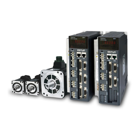
Estun Trio DX4 User manual


DX4 Product Manual
D
ocument Version:
V1.04
(
Jan, 2021
)
© 2020 Trio Motion Technology Ltd. All right reserved. i
About this Manual
Purpose
This manual provides the information required for the Selection, Wiring, Connection, Setup, Trial
Operation, Tuning and Functions of the DX4 Servo Drive (referred to as DX4).
Please read and understand this manual to ensure correct usage of the product.
Terms
Terms that may be used in this manual are defined as follows.
Term Meaning
Motor A Rotary Servo Motor.
Drive A Servo Drive, which is used for controlling the motion of the Motor.
Servo System A Servo Control System that includes a Motor, a Drive with a host controller and
peripheral devices.
Servo ON Supplying power to the Motor.
Servo OFF Not supplying power to the Motor.
Motion Perfect The PC Tool for commissioning and programming the Trio product suite.
STO The Safe Torque Off function provides a safe means for preventing the Drive from
generating torque in the Motor.
Fully Closed Loop Dual encoder feedback

DX4 Product Manual
D
ocument Version:
V1.04
(
Jan, 2021
)
© 2020 Trio Motion Technology Ltd. All right reserved. ii
Symbols
The symbols that may be found in this document are defined as follows.
Symbol Description
DANGER
Indicates a hazard with a high level of risk that, if not avoided, may result in death or
serious injury.
WARNING
Indicates a hazard with a medium or low level of risk which, if not avoided, could result in
minor or moderate injury.
CAUTION
Indicates a potentially hazardous situation that, if not avoided, could cause equipment
damage, loss of data, performance degradation, or unexpected results.
IMPORTANT
Indicates precautions or restrictions that must be observed.
Also indicates alarm displays and other precautions that will not result in machine damage.
NOTE
Provides additional information to emphasize or supplement important points of the main
text.
The names of inverted signals (ones that are taken effect when low) are written with a forward slash (/)
before the signal abbreviation. For example:
S-ON = /S-ON P-CON = /P-CON
Parameters are referenced as PnXXX where XXX refers to a unique number. Some parameters have
multiple functions encoded within a single parameter. For these parameters, sub-indices are used to
reference the multiple functions.
For example:
Pn112 Speed Feedforward - is a single value without any sub-indices
Pn000 Basic Function Selection 0 - is made up of 4 sub-indexes describing different functions
Pn000.0 Servo ON
Pn000.1 Forward Drive Prohibit Input (P-OT)
Pn000.2 Reverse Drive Prohibit Input (N-OT)
Pn000.3 Reserved parameter (Do not change)

DX4 Product Manual
D
ocument Version:
V1.04
(
Jan, 2021
)
© 2020 Trio Motion Technology Ltd. All right reserved. iii
Safety Precautions
General Precautions
DANGER
Never remove covers, cables, connectors, or optional devices while power is being
supplied to the Drive.
Wait for five minutes after turning the power supply OFF and then make sure that
the CHARGE indicator is not lit before starting wiring or inspection work.
Never touch the power supply terminals after turning OFF the power supply while
the CHARGE lamp is lit, because high voltages may still be present in the Drive.
WARNING
Use a power supply that is appropriate for the product, check number of phases,
voltage, frequency, and AC/DC type.
Connect the ground terminals on the Drive and Motor to ground poles according to
local electrical codes.
Never damage, pull on, apply excessive force to, place heavy objects on, or pinch
cables.
Never attempt to disassemble, repair, or modify the product.
Make sure that the device in an emergency stop state at any time when the product
has been connected to the machine and ready for the operation.
Never touch inside the Drive.
CAUTION
The Drive heat sinks, regenerative resistors, Motor, and other components can be
very hot while power is ON or soon after the power is turned OFF. Implement safety
measures, such as installing covers, so that hands and parts such as cables do not
come into contact with hot components.
For the control power supply, use a power supply device with double insulation or
reinforced insulation.
Never use the product in an environment that is subject to water, corrosive gases,
or flammable gases, or near flammable materials.
Never attempt to use a Drive or Motor that is damaged or that has missing parts.
Install external emergency stop circuits that shut OFF the power supply and stops
operation immediately when an error occurs.
In locations with poor power supply conditions, install the necessary protective
devices (such as AC reactors) to ensure that the input power is supplied within the
specified voltage range.
Always use a Noise Filter to minimize the effects of electromagnetic interference.
Always use a Motor and Drive in one of the specified combinations.
Never touch a Drive or Motor with wet hands.

DX4 Product Manual
D
ocument Version:
V1.04
(
Jan, 2021
)
© 2020 Trio Motion Technology Ltd. All right reserved. iv
Storage Precautions
CAUTION
Follow all instructions on the packages, and never place an excessive load on the
product during storage.
Never install or store the product in any of the following locations.
Locations that are subject to direct sunlight
Locations that are subject to ambient temperatures that exceed product specifications
Locations that are subject to relative humidity that exceed product specifications
Locations that are subject to corrosive or flammable gases
Locations that are subject to dust, salts, or iron powder
Locations that are subject to water, oil, or chemicals
Locations that are subject to vibration or shock that exceeds product specifications
Locations that are subject to radiation
Installation Precautions
CAUTION
Install the Drive in a control cabinet that provides fire and electrical protection.
Install the Drive and Motor in a way that will support their mass.
Never install or store the product in any of the following locations.
Locations that are subject to direct sunlight
Locations that are subject to ambient temperatures that exceed product specifications
Locations that are subject to relative humidity that exceed product specifications
Locations that are subject to corrosive or flammable gases
Locations that are subject to dust, salts, or iron powder
Locations that are subject to water, oil, or chemicals
Locations that are subject to vibration or shock that exceeds product specifications
Locations that are subject to radiation
Never allow any foreign matter to enter a Drive or a Motor with a Cooling Fan.
Never cover the outlet from cooling fan of Drive or Motor.
Never step on or place a heavy object on the product.
Install the Drive in the specified orientation.
Provide the specified clearances between the Drive and the control cabinet as well
as with other devices.
Wiring Precautions
CAUTION
Never bypass the electromagnetic contactor in the wiring between the Drive and the
Motor.
Firmly connect the power terminal to the Motor terminal.
Provide an adequate air gap around the Drive installation.
Use shielded twisted-pair cables or screened unshielded multi-twisted-pair cables for
I/O Signal Cables and Encoder Cables.
The wiring length of the command input line is up to 3 meters, and the wiring length
of the encoder is up to 20 meters.
Minimize the frequency that the power supply is turned ON and OFF.

DX4 Product Manual
D
ocument Version:
V1.04
(
Jan, 2021
)
© 2020 Trio Motion Technology Ltd. All right reserved. v
Operation Precautions
CAUTION
In order to prevent accidents, please test the Motor with no load (not connected to
the Drive shaft).
When starting to operate on the supporting machine, set the user parameters that
match the machine in advance.
Note that the signals for the Forward Drive Prohibit (P-OT) and the Reverse Drive
Prohibit (N-OT) are disabled during JOG operation.
When overtravel occurs, the power supply to the Motor is turned OFF and the brake is
released. If the Motor is used to drive a vertical load, set the Motor to enter a ‘zero-
clamped’ state after the Motor stops. Also, install safety devices (such as an external
brake or counterweight) to prevent the moving parts of the machine from falling.
If not using auto-tuning, make sure that an appropriate moment of inertia ratio is
setup to avoid vibration.
If an alarm occurs, reset it after troubleshooting the cause and ensuring safety.
Never use the brake of the Motor for normal braking.
Maintenance Precautions
WARNING
Wiring and inspections must be performed only by qualified engineers.
Disconnect all connections to the Drive when testing the insulation resistance of the
Drive.
Never use gasoline, thinner, alcohol, acid or alkaline detergent to avoid discoloration
or damage to the casing.
When replacing the Drive, transfer the user parameters from the replaced Drive to
new Drive.
Never change the wiring while the power is on.
Never disassemble the Motor without permission.
Disposal Precautions
CAUTION
When disposing of the product, treat it as ordinary industrial waste. However,
local ordinances and national laws must be observed. Implement all labeling
and warnings as required.

DX4 Product Manual
D
ocument Version:
V1.04
(
Jan, 2021
)
© 2020 Trio Motion Technology Ltd. All right reserved. i
Contents
Chapter 1 DX4 Servo Drive ...................................................................... 1-1
1.1 Product Features ........................................................................................ 1-1
1.2 Interpreting the Nameplate ........................................................................... 1-2
1.3 Model Designations ..................................................................................... 1-2
1.4 Part Names ............................................................................................... 1-3
1.5 Ratings and Specifications ............................................................................. 1-4
1.6 External Dimensions .................................................................................... 1-6
1.7 System Configuration ................................................................................... 1-7
Chapter 2 Installation ............................................................................ 2-1
2.1 Installation Precautions ................................................................................ 2-1
2.2 Mounting Types and Orientation ...................................................................... 2-1
2.3 Mounting Hole Dimensions ............................................................................. 2-2
2.4 Mounting Interval ....................................................................................... 2-2
Chapter 3 Wiring and Connections ............................................................. 3-1
3.1 Precautions for Wiring .................................................................................. 3-1
3.2 Basic Wiring Diagrams .................................................................................. 3-7
3.3 Power Supply (X1, X2) .................................................................................. 3-8
3.4 Motor Power (X3) ...................................................................................... 3-13
3.5 EtherCAT Communication (X4, X5) ................................................................. 3-14
3.6 Connecting STO Function Signals (X6) ............................................................. 3-15
3.7 I/O Connector (X7) ................................................................................... 3-15
3.8 Encoder (X8) ........................................................................................... 3-16
Chapter 4 STO .................................................................................... 4-19
4.1 Introduction ............................................................................................ 4-19
4.2 Environmental Conditions ........................................................................... 4-22
4.3 Terminals Arrangement (X6) ......................................................................... 4-23
4.4 Function Description ................................................................................. 4-24
4.5 Safety Function Device Connection ................................................................ 4-27
4.6 Procedure .............................................................................................. 4-30
Chapter 5 Status Display ......................................................................... 5-1
5.1 Motor Control Status Display .......................................................................... 5-1
5.2 Network Status Indicators ............................................................................. 5-3
Chapter 6 Commissioning ........................................................................ 6-1
6.1 Motion Perfect ........................................................................................... 6-1
6.2 Setup ...................................................................................................... 6-1
6.3 Drive Commissioning Screens ......................................................................... 6-4
6.4 Basic Operation ......................................................................................... 6-7
Chapter 7 Tuning .................................................................................. 7-1
7.1 Tuning Process ........................................................................................... 7-2
7.2 Tuning Modes............................................................................................. 7-4
7.3 Compensation ......................................................................................... 7-12
7.4 Vibration Suppression ................................................................................ 7-17
7.5 Gain Scheduling ....................................................................................... 7-21
7.6 Model Control Following ............................................................................. 7-24

DX4 Product Manual
D
ocument Version:
V1.04
(
Jan, 2021
)
© 2020 Trio Motion Technology Ltd. All right reserved. ii
7.7 Load Identification.................................................................................... 7-25
Chapter 8 Fully Closed Loop Operation ..................................................... 8-31
8.1 Commissioning Procedure ........................................................................... 8-32
8.2 Enable External Encoder ............................................................................. 8-32
8.3 Motor Direction and Machine Movement ............................................................ 8-1
8.4 Alarm Detection Settings .............................................................................. 8-1
Chapter 9 Appendix ............................................................................... 9-3
9.1 EtherCAT Communications ............................................................................. 9-3
9.2 Object Dictionary ....................................................................................... 9-1
9.3 Parameter List ......................................................................................... 9-16
9.4 Alarms Displays ........................................................................................ 9-29
Chapter 10 Revision History ................................................................ 10-39

DX4 Product Manual
DX4 Servo Drive
Document Version: V1.04 (Jan, 2021)
©
20
20
Trio Motion Technology Ltd.
All right reserved.
1
-
1
Chapter 1 DX4 Servo Drive
1.1 Product Features
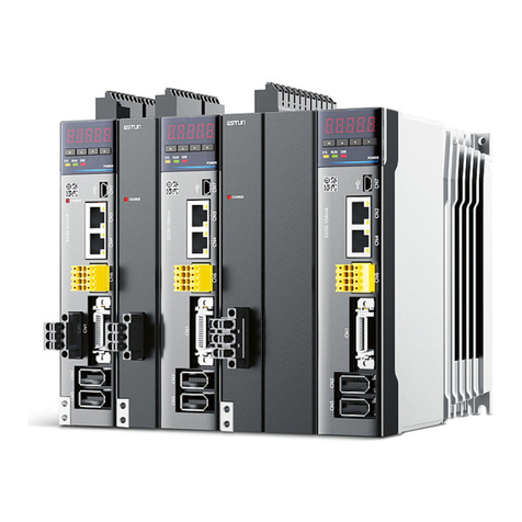
The DX4 single axis AC servo drive is designed to work seamlessly with Trio controller and is fully
integrated into Trio’s application development tool, Motion Perfect. It comes in power ratings from 50 W
to 3 kW. Matched with the MX motors it offers a high-speed, high-precision machine solution.
Integration into Motion Perfect allows complete machine configuration from one tool: commissioning,
diagnostics and programming.
With a focus on performance and ease-of-use the DX4 maximizes machine performance while minimizing
application development time.
Features
Drive and Motion Controller fully integrated into Motion Perfect
EtherCAT support, update rates down to 125 µs
Compact size
Zero stacking gap installation
Functional Safety Dual STO (SIL3, PLe)
200 V ac from 50 W to 3 kW
Matched with MX motor range of low and medium inertia motors
20-bit incremental or 23-bit absolute encoder interface
Internal drive protection functions
7 digital inputs, 2 dedicated touch probe inputs for position latching
4 digital outputs, external encoder interface for dual encoder applications
Comprehensive tuning technology including: Auto-tuning function, adaptive vibration suppression,
friction compensation
EtherCAT® is a registered trademark and patented technology, licensed by Beckhoff Automation GmbH,
Germany.

DX4 Product Manual
DX4 Servo Drive
Document Version: V1.04 (Jan, 2021)
©
20
20
Trio Motion Technology Ltd.
All right reserved.
1
-
2
1.2 Interpreting the Nameplate
1.3 Model Designations
DX4 -
1 Single axis A5 50W A 200VAC J EtherCAT + STO A -
01 100W
02 200W
04 400W
08 750W
10 1kW
15 1.5kW
20 2kW
30 3kW
Options Design SequenceNumber of axes Output Power Voltage
Drive Model
Rated Input Rated Output
Serial Number

DX4 Product Manual
DX4 Servo Drive
Document Version: V1.04 (Jan, 2021)
©
20
20
Trio Motion Technology Ltd.
All right reserved.
1
-
3
1.4 Part Names
No. Name Description
X1 Control Circuit Connector Control power supply (5 pins)
X2 Main Circuit Connector Main circuit power supply (6 pins)
a Status Display Drive status display
b CHARGE Indicator Lamp Main circuit power supply indicator
(1)
X3 Motor Connector Motor power
c Grounding Terminal Ground terminal for motor power cable
X4 EtherCAT Input Connector EtherCAT input (RJ45)
X5 EtherCAT Output Connector EtherCAT output (RJ45)
X6 Safety Connector Safe Torque Off (STO)
X7 I/O Signal Connector Digital I/O and external encoder input
X8 Encoder Connector Encoder signals
(1): When the main circuit power is turned OFF, the CHARGE indicator will be lit as long as the internal capacitor
remains charged. Do not touch the main circuit or Motor terminals while this indicator is illuminated as there is
possibility of electric shock.
X1
X2
a
b
X3
X4
X5
X6
X7
X8
c

DX4 Product Manual
DX4 Servo Drive
Document Version: V1.04 (Jan, 2021)
©
20
20
Trio Motion Technology Ltd.
All right reserved.
1
-
4
1.5 Ratings and Specifications
Drive Model: DX4 1A5A 101A 102A 104A 108A 110A 115A 120A 130A
Continuous Output Current [Arms] 0.9 1.1 1.5 2.9 5.1 6.9 8.2 11.3 16.0
Instantaneous Maximum Output
Current [Arms] 3.3 4.0 5.8 11.5 19.5 21.0 24.6 33.9 54.0
Power Supply
Capacity [kVA]
Single-phase 0.2 0.3 0.6 1.2 1.9 2.6 4.0 - -
Three-phase 0.2 0.3 0.5 0.9 1.6 2.0 3.0 3.5 4.5
Power Supply
Main Circuit
Single-phase or Three-phase 200 V ac to 240 V ac
-15% to +10%, 50 Hz or 60 Hz
270 V dc to 324 V dc
-15% to +10%
DX4-115* is de-rated to 1.2kW when used with a single-phase
supply
DX4-120* and DX4-130* can only be used with a three-phase
supply
Control Circuit
Single-phase 200 V ac to 240 V ac
-15% to +10%, 50 Hz or 60 Hz
270 V dc to 324 V dc
-15% to +10%
Control Method SVPWM
Feedback
Serial encoder:
20-bits single-turn incremental encoder
23-bits single-turn, 16-bits multi-turn absolute encoder
Environmental
Conditions
Temperature
Ambient temperature: -5˚C to 55˚C (less than 40˚C for zero-
stacking gap installation)
Storage temperature: -20˚C to +85˚C
Humidity Both operating and storage: 5% to 95% (with no condensation)
Protection Class IP20
Altitude 1,000 m or less
Vibration
Resistance 4.9 m/s2
Shock Resistance 19.6 m/s2
Power System TN System
Mounting Base-mounted
Performance
Speed Control
Range 1:5000
Coefficient of
Speed
Fluctuation
±0.01% of rated speed max. (For a load fluctuation of 0% to 100%)
0% of rated speed max. (For a rated voltage fluctuation of ±10%)
±0.1% of rated speed max. (For a temperature fluctuation of
25°C±25°C)

DX4 Product Manual
DX4 Servo Drive
Document Version: V1.04 (Jan, 2021)
©
20
20
Trio Motion Technology Ltd.
All right reserved.
1
-
5
I/O Signals
External Encoder
Input
Supports A, B, and Z TTL differential type sensor signal.
Maximum line frequency of 500kHz.
Input Signals
Allowable voltage range: 24 V dc ±20%
Number of input points: 7 (2 for high-speed optocoupler inputs,
fixed as Touch Probe)
Touch Probe Signals are TP1 (Touch Probe 1), TP2 (Touch Probe
2).
All other inputs are general purpose but can be assigned specific
functions during commissioning. These inputs can also be
inverted so act as active-low.
Output Signals
Allowable voltage range: 5 V dc to 30 V dc
Number of output points: 4
All outputs are general purpose but can be assigned specific
functions during commissioning. These outputs can also be
inverted so act as active-low.
EtherCAT
Communications
Applicable
Communications
Standards
IEC 61158 Type12, IEC 61800-7 CiA402 Drive Profile
Physical Layer 100BASE-TX (IEEE802.3)
Communications
Connectors
X4-IN (RJ45): EtherCAT signal input connector
X5-OUT (RJ45): EtherCAT signal output connector
Cable Category 5, Shielded/Foiled Twisted Pairs (CAT5e SF/UTP)
Sync Manager SM0: Mailbox output, SM1: Mailbox input, SM2: Process data
output, and SM3: Process data input
FMMU
FMMU 0: Mapped in process data output (RxPDO) area.
FMMU 1: Mapped in process data input (TxPDO) area.
FMMU 2: Mapped to mailbox status.
EtherCAT
Commands
(Data Link Layer)
APRD, FPRD, BRD, LRD, APWR, FPWR, BWR, LWR, ARMW, FRMW
(APRW, FPRW, BRW, and LRW commands are not supported.)
Process Data Assignments can be changed with PDO mapping.
MailBox (CoE) Emergency messages, SDO requests, SDO responses
(TxPDO/RxPDO and remote TxPDO/RxPDO are not supported.)
Distributed
Clocks
Free-Run Mode and DC Mode (Can be switched)
Applicable DC cycles: 125 μs to 8 ms
Slave
Information
Interface
256 bytes (read-only)
CiA402 Drive Profile
Cyclic Synchronous Position Mode
Cyclic Synchronous Velocity Mode
Cyclic Synchronous Torque Mode
Touch Probe Function
Torque Limit Function
Display One 7-segment LED

DX4 Product Manual
DX4 Servo Drive
Document Version: V1.04 (Jan, 2021)
©
20
20
Trio Motion Technology Ltd.
All right reserved.
1
-
6
1.6 External Dimensions
DX4-1A5*
to
DX4-104*
DX4-108
* to
DX4-115*
Indicator Lamps CHARGE, POWER, RUN, SYS, ERR, L/A IN, L/A OUT
Regenerative Processing
DX4-1A5*, DX4-101*, DX4-102* and DX4-104* must connect an
external regenerative resistor.
Other models are built in.
Protective Functions Overcurrent, Overvoltage, Undervoltage, Overload, Regeneration
Error, Overspeed, etc.
Utility Functions Alarm history, Jogging, Load inertia identification, Auto-Tuning,
etc.
Safe Torque Off According to IEC 61800-5-2. Cat.4, PLe according to ISO 13849-1,
SIL3 according to IEC 61508, IEC 62061.

DX4 Product Manual
DX4 Servo Drive
Document Version: V1.04 (Jan, 2021)
©
20
20
Trio Motion Technology Ltd.
All right reserved.
1
-
7
DX4-120
* to
DX4-130*
1.7 System Configuration
Example Diagram

DX4 Product Manual
DX4 Servo Drive
Document Version: V1.04 (Jan, 2021)
©
20
20
Trio Motion Technology Ltd.
All right reserved.
1
-
8
Minimum system configuration is:
Power Supply
Breaker
Filter
Contactor
Regen resistor
Drive
Motor
Controller
PC for commissioning
Cables (encoder, motor power, EtherCAT, Ethernet, STO, IO cable)
Peripheral Devices Specification
Device Name Description Specification
Circuit Breaker
Used to protect the power supply
line and cut off the circuit when an
overcurrent occurs.
The minimum rated current of the circuit
breaker depends on the Drive model.
Use Type C MCB
Drive Model Circuit Breaker
DX4-1A5*
DX4-101*
5A
DX4-102*
DX4-104*
10 A
DX4-108*
DX4-110*
25 A
DX4-115* 35 A
DX4-120* 55 A
DX4-130* 70 A
Noise Filter
Used to prevent external noise
interference from the power
supply.
The rated current is 10 A or 20 A.

DX4 Product Manual
DX4 Servo Drive
Document Version: V1.04 (Jan, 2021)
©
20
20
Trio Motion Technology Ltd.
All right reserved.
1
-
9
Device Name Description Specification
External
Regenerative
Resistor
When the busbar capacitance is
insufficient, remove the short
wiring between B2 and B3, and
connect an external regenerative
resistor between B1 and B2. (1)
Ensure that Pn535 and Pn536 are
both set to reflect the resistor
value.
The minimum value of the regenerative
resistor depends on the Drive model.
Drive Model Regenerative Resistor
DX4-1A5*
DX4-101*
DX4-102*
DX4-104*
DX4-108*
DX4-110*
25 Ω
DX4-115*
DX4-120*
DX4-130*
10 Ω
(1): DX4-1A5*, DX4-101*, DX4-102* and DX4-104* must connect an external regenerative resistor.

Document Version: V1.04 (Jan, 2021)
©
20
20
Trio Motion Technology Ltd.
All right reserved.
2
-
1
Chapter 2 Installation
2.1 Installation Precautions
Installation Near Sources of Heat
Implement measures to prevent temperature increases caused by external heat sources so that the
ambient temperature of the Drive is within the specified limits.
Installation Near Sources of Vibration
Install a vibration absorber on the installation surface of the Drive so that the Drive will not be subjected
to vibration.
Other Precautions
Never install the Drive in a location subject to high temperatures, high humidity, water drops, cutting oil,
excessive dust, excessive dirt, excessive iron powder, corrosive gasses, or radioactivity.
2.2 Mounting Types and Orientation
The Drives are based mounted and should be fitted to a non-painted metal surface. Mount the Drive
vertically, as is shown in Figure 2-1.
Mount the Drives so that the Display Panel is facing toward the operator. Prepare two or three mounting
holes for the Drive and mount it securely in the mounting holes (The number of mounting holes depends
on the size of the Drive).
Figure 2-1 Base-mounted diagram

Document Version: V1.04 (Jan, 2021)
©
20
20
Trio Motion Technology Ltd.
All right reserved.
2
-
2
2.3 Mounting Hole Dimensions
Use all mounting holes to securely mount the Drive to the mounting surface.
To mount the Drive, use a screwdriver that is longer than the depth of the Drive.
2.4 Mounting Interval
Installing One Drive in a Control Cabinet
When installing a single Drive use Figure 2-2 as a reference for free space around the installation.
Figure 2-2 Installing a single Drive in a control cabinet

Document Version: V1.04 (Jan, 2021)
©
20
20
Trio Motion Technology Ltd.
All right reserved.
2
-
3
Installing multiple Drives in a Control Cabinet
When installing a multiple Drives use Figure 2-3 as a reference for free space around the installation.
Figure 2-3 Installing multiple Drives in a control cabinet
NOTE
The DX4 can be mounted so that the distance between adjacent Drives is 1mm.
Other manuals for Trio DX4
1
Table of contents
Other Estun Servo Drive manuals
Popular Servo Drive manuals by other brands

Welcon
Welcon WEC-D048/08-FS0025-E Hardware manual

Indel
Indel GIN-SAC4x4 Series Hardware user manual

Omron
Omron SMARTSTEP Junior user manual

Rockwell Automation
Rockwell Automation Allen-Bradley Kinetix 5500 user manual

Rockwell Automation
Rockwell Automation Allen-Bradley Kinetix 7000 user manual

Kinco
Kinco FD3 User Guidance Manual