Elisa EPR628S1 Datasheet
Installation Instructions Guide
Instructions d’installation Guide
Guía de Instrucciones para Instalación
READ AND SAVE THESE INSTRUCTIONS
INSTRUCTIONS D’INSTALLATION GUIDE
LEA Y GUARDE ESTAS INSTRUCCIONES
Model: EPR628SS
English p. 3
Français p. 14
Español p. 25
Model: EAS428SS
LI31MB


3
WARNING: TO REDUCE THE RISK OF FIRE, ELECTRIC
SHOCK, OR INJURY TO PERSONS, OBSERVE THE
FOLLOWING:
■Use this unit only in the manner intended by the
manufacturer. If you have questions, contact the
manufacturer.
■Before servicing or cleaning the unit, switch power off at
service panel and lock the service disconnecting means to
prevent power from being switched on accidentally. When
the service disconnecting means cannot be locked, securely
fasten a prominent warning device, such as a tag to the
service panel.
■Installation work and electrical wiring must be done by
qualiedperson(s)inaccordancewithallapplicablecodes
andstandards,includingre-ratedconstruction.
■Sufcientairisneededforpropercombustionand
exhaustingofgasesthroughtheue(chimney)offuel
burning equipment to prevent backdrafting. Follow the
heating equipment manufacturer’s guideline and safety
standards such as those published by the National Fire
ProtectionAssociation(NFPA),theAmericanSocietyfor
Heating, Refrigeration and Air Conditioning Engineers
(ASHRAE),andthelocalcodeauthorities.
■When cutting or drilling into wall or ceiling; do not damage
electrical wiring and other utilities.
■Ducted fans must always be vented outdoors.
CAUTION: For general ventilating use only. Do not use to
exhaust hazardous or explosive materials and vapors.
CAUTION: Toreduceriskofreandtoproperlyexhaustair,
besuretoductairoutside-donotventexhaustairinto
spaces within walls or ceilings, attics or into crawl spaces, or
garages.
WARNING: TO REDUCE THE RISK OF FIRE, USE ONLY
METAL DUCTWORK
READ AND SAVE THESE INSTRUCTIONS
IMPORTANT SAFETY INSTRUCTIONS
WARNING: TO REDUCE THE RISK OF A RANGE TOP
GREASE FIRE:
■Never leave surface units unattended at high settings.
Boilovers cause smoking and greasy spillovers that may
ignite. Heat oils slowly on low or medium settings.
■Always turn hood ON when cooking at high heat or when
ambeingfood(i.e.CrepesSuzette,CherriesJubilee,
PeppercornBeefFlambé).
■Clean ventilating fans frequently. Grease should not be
allowedtoaccumulateonfanorlter.
■Use proper pan size. Always use cookware appropriate for
the size of the surface element.
WARNING: TOREDUCETHERISKOFINJURYTO
PERSONS IN THE EVENT OF A RANGE TOP GREASE FIRE,
OBSERVE THE FOLLOWING:a
■SMOTHERFLAMESwithaclosettinglid,cookiesheet,or
metal tray, then turn off the burner. BE CAREFUL TO
PREVENTBURNS.Iftheamesdonotgoout
immediately, EVACUATE AND CALL THE FIRE
DEPARTMENT.
■NEVERPICKUPAFLAMINGPAN-youmaygetburned.
■DONOTUSEWATER,includingwetdishclothsortowels-
a violent steam explosion will result.
■Use an extinguisher ONLY if:
-YouknowyouhaveaclassABCextinguisher,andyou
already know how to operate it.
–Thereissmallandcontainedintheareawhereit
started.
–Theredepartmentisbeingcalled.
–Youcanghttherewithyourbacktoanexit.
aBased on “Kitchen Fire Safety Tips” published by NFPA.
WARNING: Toreducetheriskofreorelectricalshock,
donotusethisfanwithanysolid-statespeedcontrol
device.
APPROVED FOR RESIDENTIAL APPLIANCES
FOR RESIDENTIAL USE ONLY
READ AND SAVE THESE INSTRUCTIONS
PLEASE READ ENTIRE INSTRUCTIONS BEFORE PROCEEDING.
INSTALLATION MUST COMPLY WITH ALL LOCAL CODES.
IMPORTANT: Save these Instructions for the Local Electrical
Inspector’s use.
INSTALLER: Please leave these Instructions with this unit for
the owner.
OWNER: Please retain these instructions for future
reference.
Safety Warning:Turn off power circuit at service panel and lock
out panel before wiring this appliance.
Requirement 120 VAC, 60 Hz. 15 or 20 A Branch Circuit
Table of Contents
Important Safety Notice .......................................................... 3
Tools and parts ........................................................................ 4
Location Requirements ...................................................... 4
Product Dimensions ........................................................... 4
Venting Requirements ........................................................5
Venting Methods ................................................................ 6
Calculating Vent System Length ........................................ 6
Electrical Requirements...........................................................6
Installation Instructions .......................................................... 7
Prepare Location.................................................................7
Install range hood.....................................................................9
Connect the Vent System....................................................10
Complete Installation...........................................................10
Range Hood Use....................................................................... 11
Range Hood Care......................................................................11
Available Accessories.............................................................. 12
Warranty.....................................................................................13

4
Tools and Parts
Gather the required tools and parts before starting installation.
Read and follow the instructions provided with any tools listed
here.
Tools needed (all models)
■Level
■Drill
■ ¹⁄8”(3.0mm)drillbit
■Pencil
■Pliers
■Tape measure or ruler
■Caulking gun and weatherproof caulking compound
■ Flat-bladescrewdriver
■Phillips screwdriver
■Saber or keyhole saw
■Metal snips
■Vent clamps
Parts Supplied
Remove parts from packages. Check that all parts are included.
■ 1-30”x12”(76.2x30.5cm)facepanel
■Damper
■ 2-40Wincandescentlamps(onlymodelEAS428SS)
■ 2-50Whalogenlamps(onlymodelEPR628SS)
■ 2-Metalgreaselters
■ 2-Mountingbrackets
■ 2-Metalspacers(forusewhencabinetdepthisgreater
than12”)
■Hardware package. Includes:
• Installation Instructions and Use and Care Guide
• 8-metalwashers
• 8-plasticwashers
• 8-4.5x13mmwoodscrews
• 2-4.2x15mmmachinescrews
• 4-3.5x9.5mmat-headsheetmetalscrews
• 8-4.2x19mmsheetmetalscrews
• 6-3.5x9.5mmsheetmetalscrews
• T10 TORX®† adapter
Parts needed
■ 6”(15.2cm)roundmetalventsystem
†®TORX is a registered trademark of Saturn Fasteners, Inc.
Location Requirements
IMPORTANT: Observe all governing codes and ordinances.
Haveaqualiedtechnicianinstalltherangehood.Itisthe
installer’s responsibility to comply with installation clearances
speciedonthemodel/serialratingplate.Themodel/serialrating
plateislocatedinsidethelinerbehindthelterontheleftwallof
the range hood.
Range hood location should be away from strong draft areas,
such as windows, doors, and strong heating vents.Cabinet open-
ing dimensions that are shown must be used. Given dimensions
provideminimumclearance.Consultyourcooktop/rangemanu-
facturer installation instructions before making any cutouts.
Grounded electrical outlet is required. See “Electrical Require-
ments” section.
The range hood is factory set for vented installations through the
rooforwall.Fornon-vented(recirculating)installationssee“Non-
Vented(recirculating)InstallationThroughtheSoft/Cabinet”in
the “Prepare Location” section. Recirculation Kit Part is available
from your dealer or an authorized parts distributor. All openings
in ceiling and wall where range hood will be installed must be
sealed.
For Mobile Home Installations
The installation of this range hood must conform to the
Manufactured Home Construction Safety Standards, Title 24
CFR,Part328(formerlytheFederalStandardforMobileHome
ConstructionandSafety,title24,HUD,Part280)orwhensuch
standard is not applicable, the standard for Manufactured Home
Installation1982(ManufacturedHomeSites,Communitiesand
Setups)ANSIA225.1/NFPA501A,orlatestedition,orwithlocal
codes.
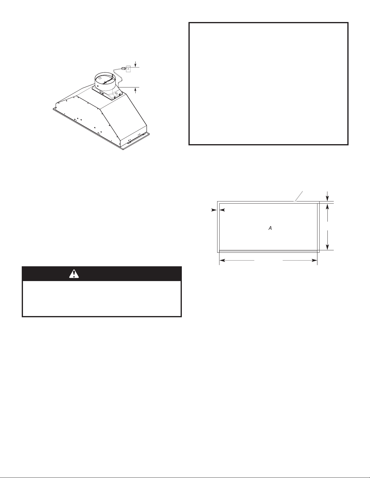
Product Dimensions
I*
I*
I*-Metallicspacers
Spacers has to be installed
and used when cabinet depth
is greater than 12”.
EAS428SS / EPR628SS range hood models
Dimension
DIM A 281⁄4”(71.8cm)
DIM B 26”(66cm)
DIM C 1⅛”(2.9cm)
DIM D 10¾”(27.3cm)
DIM E 9½”(24.2cm)
DIM F 5⁄16”(.85cm)
DIM G 14 9⁄16”(37cm)
DIM H 6”(14.8cm)
DIM I ½”(1.27cm)

5
Installation Clearances
A.12”(30.5cm)min.upper
cabinet height
B.30”(76.2cm)
cabinet opening width*
C.24”(61cm)min.36”(91.4cm)
suggested max. bottom of
cabinet to cooking surface
D.12”(30.48cm)cabinet
opening depth*
E.15”(38.1cm)min.clearance
upper cabinet to countertop
F.36”(91.4cm)basecabinet
height
For gas range installation: Mount this hood so that the bottom
edgeisatminimum27”(68,5cm)abovethecookingsurface.
For electric range installation: mount this hood so that the bottom
isnotlessthan24”(61cm).
*NOTE:Thisrangehoodissetto30”(76.2cm)cabinetwidthx
12”(30.5cm)deepcabinets.
VENTING REQUIREMENTS
■Vent system must terminate to the outdoors, except for no
vented(recirculating)installations.
■Do not terminate the vent system in an attic or other enclosed
area.
■ Donotusea4”(10.2cm)laundry-typewallcap.
■Use metal vent only. A rigid metal vent is recommended.
Plastic or metal foil vent is not recommended.
■The length of the vent system and number of elbows should
bekepttoaminimumtoprovideefcientperformance.
Forthemostefcientandquietoperation:
■Use no more than three 90° elbows.
■ Makesurethereisaminimumof24”(61.0cm)ofstraight
vent between the elbows if more than 1 elbow is used.
■Do not install 2 elbows together.
■The vent system must have a damper.
■Use clamps to seal all joints in the vent system.
■Use caulking to seal exterior wall or roof opening around the
cap.
■The size of the vent should be uniform.
Cold weather installations
An additional back draft damper should be installed to minimize
backwardcoldairowandathermalbreakshouldbeinstalledto
minimize conduction of outside temperatures as part of the vent
system. The damper should be on the cold air side of the thermal
break.
The break should be as close as possible to where the vent
system enters the heated portion of the house.
Makeup air
Local building codes may require the use of makeup air systems
whenusingventilationsystemswithgreaterthanspeciedCFM
ofairmovement.ThespeciedCFMvariesfromlocaletolocale.
ConsultyourHVACprofessionalforspecicrequirementsinyour
area.

6
Venting Methods
This range hood is factory set for venting through the roof or
through the wall. You can apply the recirculating venting method
by purchasing the Recirculation Kit.
The vent system needed for installation is not included.
A6”(15.2cm)roundventsystemisrecommended.
Roof Venting
A.6”(15.2cm)vent
through the roof
B. Roof cap
Wall Venting
A.6”(15.2cm)vent
through the wall
B. Wall cap
Recirculating
A.6”(15.2cm)vent
through the cabinet
B. Round recirculating grid
Calculating Vent System Length
Therecommendedventsystemis6”(15.2cm)roundventwitha
maximumlengthof35ft(10.7m).Forthebestperformance,use
no more than three 90° elbows.
To calculate the length of the system, add the equivalent feet
(meters)foreachoftheventpiecesusedinthesystem.
Vent Piece 6” (15.2 cm)
45° elbow 2.5 ft
(0.8m)
90° elbow 5.0 ft
(1.5m)
Example Vent System
90° elbow Wall cap
2ft(0.6m)
6ft(1.8m)
Maximum Recommended Length = 35 ft (10.7 m)
1-90°elbow =5.0ft(1.5m)
1-wallcap =0.0ft(0.0m)
9ft(2.8m)straight =9.0ft(2.8m)
Length of 6” (15.2 cm) system = 14.0 ft (4.3m)
WARNING
Plug into a grounded 3 prong outlet.
Do not remove ground prong.
Do not use an adapter.
Do not use an extension cord.
Failure to follow these instructions can result in
death, re, or electrical shock.
IMPORTANT: The range hood must be electrically grounded in
accordance with local codes and ordinances, or in the absence
oflocalcodes,withtheNationalElectricalCode,ANSI/NFPA70
(latestedition)orCanadianElectricalCode,CSAC22.1
No.0-M91(latestedition).
If codes permit and a separate ground wire is used, it is
recommendedthataqualiedelectricalinstallerdeterminethat
the ground path is adequate.
Electrical Requirements
A copy of the above code standards can be obtained from:
National Fire Protection Association
1 Batterymarch Park
Quincy,MA02169-7471
CSA International
8501 East Pleasant Valley Road
Cleveland,Ohio44131-5575
■ A 120 volt, 60 Hz, AC only, 15- or 20-amp, fused electrical
circuitisrequired.Atime-delay fuseorcircuitbreakeris also
recommended. It is recommended that a separate circuit
serving only this range hood be provided.
■This range hood is equipped with a power supply cord having
a 3 prong grounding plug.
■To minimize possible shock hazard, the cord must be
plugged into a mating, 3 prong, grounding-type outlet,
grounded in accordance with local codes and ordinances. If a
mating outlet is not available, it is the personal responsibility
and obligation of the customer to have the properly grounded
outletinstalledbyaqualiedelectrician.
7
Installation Instructions
■The grounded 3 prong outlet is to be located inside the
cabinet above the range hood at a maximum distance of
337⁄16” (85.0 cm) from where the power cord exits the hood.
The grounded 3 prong outlet must be accessible after
installation of the range hood. See illustration.
33 7⁄16(85cm)
GROUNDING INSTRUCTIONS
■ Foragrounded,cord-connectedrangehood:
This range hood must be grounded. In the event of an
electrical short circuit, grounding reduces the risk of electric
shock by providing an escape wire for the electric current.
This range hood is equipped with a cord having a grounding
wire with a grounding plug. The plug must be plugged into an
outlet that is properly installed and grounded.
WARNING: Improper grounding can result in a risk of electric
shock.
Consultaqualiedelectricianifthegroundinginstructionsare
not completely understood, or if doubt exists as to whether
the range hood is properly grounded.
Do not use an extension cord. If the power supply cord is too
short,haveaqualiedelectricianinstallanoutletnearthe
range hood.
SAVE THESE INSTRUCTIONS
Prepare Location
■It is recommended that the vent system be installed before
the range hood is installed.
■Before making cutouts, make sure there is proper clearance
withintheceilingorwallforventttings.
■Making the cutout to the bottom of the cabinet may be easier
to do prior to mounting the cabinet to the wall.
1. Disconnect power.
2. Determine which venting method to use: roof, wall, or non
vented.
3. Selectaatsurfaceforassemblingtherangehood.Place
covering over that surface.
WARNING
Excessive Weight Hazard
Use two or more people to move and install
range hood.
Failure to do so can result in back or other injury.
4. Using 2 or more people, lift range hood onto covered surface
Range Hood Cabinet Cutout
1. Use a saber saw or keyhole saw to cut out the cabinet
bottom inside the cabinet frame.
NOTE:Framelesstypecabinetsrequire¾”(1.9cm)frontlip
inthecabinetbottom.A¾”(1.9cm)thickllerstrip(not
supplied)mayberequiredforsometypesofcabinets.(See
Step3inthe“InstallRangeHood”section).
Cut out dimensions (without spacers)
261⁄8”(66.3cm)
107⁄8”
(27.62cm)
3⁄4”
(1.9cm)
1⁄2”
(1.27cm)
A. Bottom of cabinet cutout
2. Complete cabinet preparation following the instructions for
your type of venting. Determine venting cutout locations and
cutoutventopeningsinthecabinets,wallsand/orsoft.
8
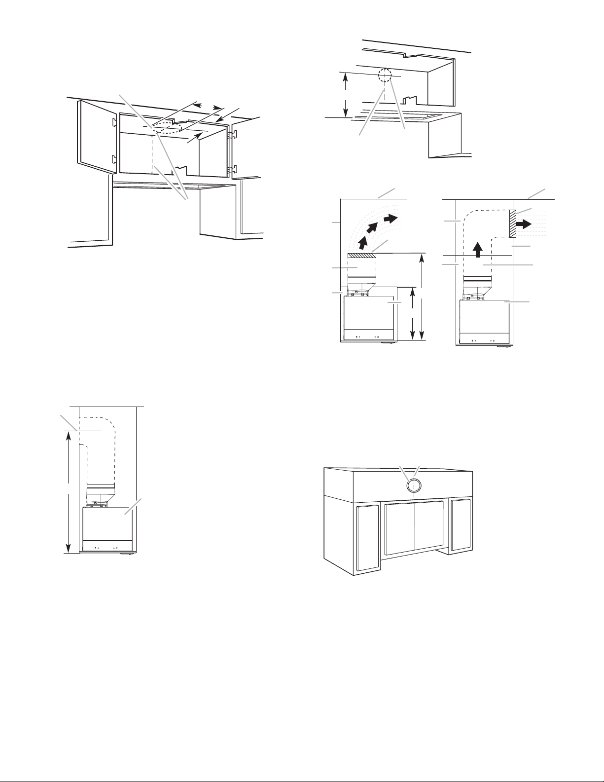
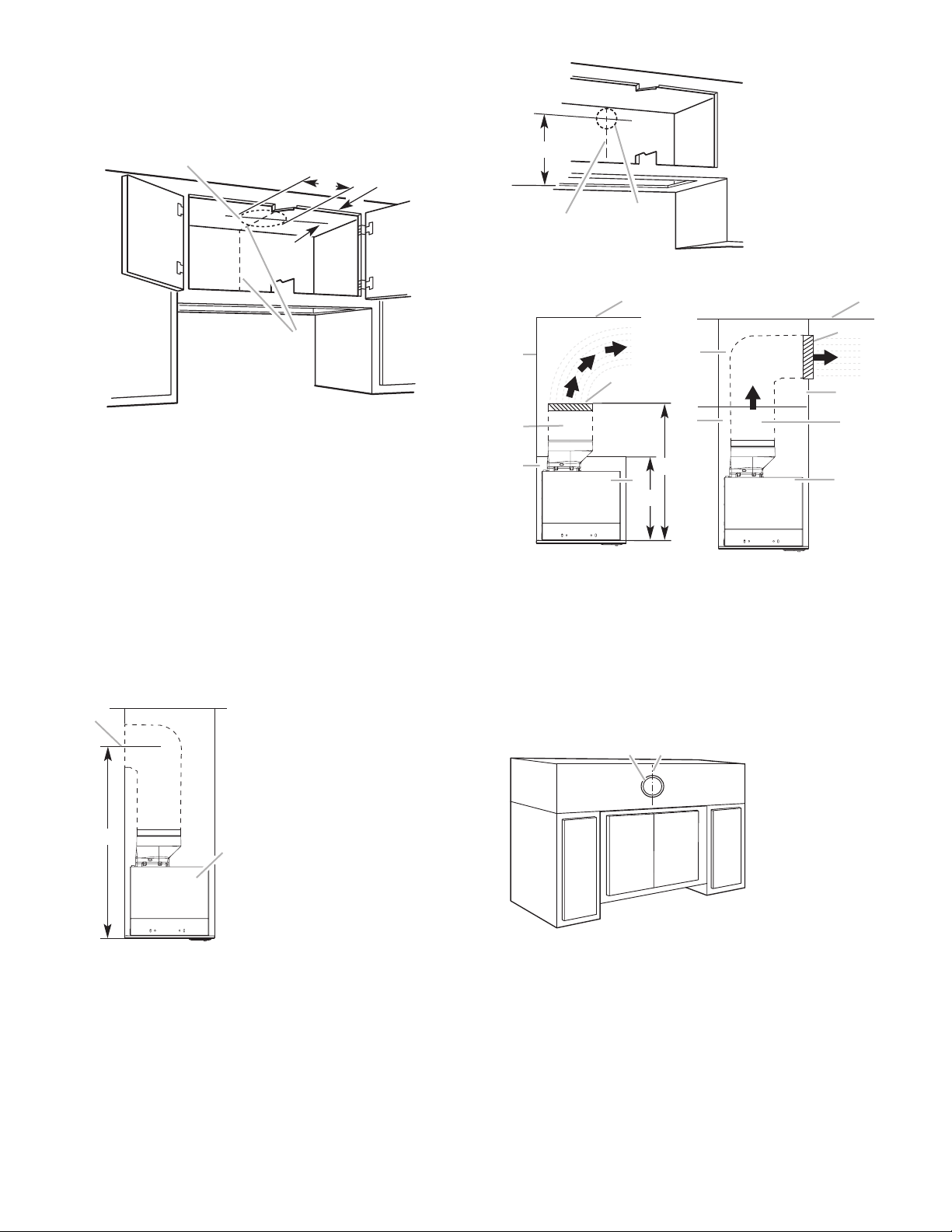
Venting Outside Through the Roof
1. Measure and mark the lines as shown. Use a saber saw or
keyhole saw to cut an opening through the top of the cabinet
and the roof for the vent.
A
B* C
D
A. Cutout
B.6¼”(15.9cm)*
C. 7¾”(19.7cm)centerlinetocabinetfront
D. Centerline
*NOTE:For12”(30.5cm)highcabinetsa6¼”deepx8”wide
(14.6cmx20.3cm)rectangularopeninginthecabinettopis
required for damper transition clearance.
Venting Outside Through the Wall
1. Installthe6”(15.2cm)venttransitiontothetopoftherange
hood liner using two 3.5 x 9.5 mm screws. Assemble the vent
ductthatyouwilluseoverthe6”(15.2cm)venttransition.
2. Measure from the bottom of the range hood liner to the
horizontalcenterlineoftheventopening(A)
A
B
C
A. Measurement A
B. Horizontal centerline of vent opening
C. Range hood liner
3. Remove the vent duct from the range hood liner.
Transfer measurement A to the cabinet back wall. Measure
from the underside of the cabinet.
4. Mark the cutout as shown. Use a saber saw or keyhole saw to
cut a round opening through the back of the cabinet and the
exterior wall for the vent. Go to Step 3.
A
B
C
A. Measurement A
B. Centerline
C.6¼”(15.9cm)round
cutout
Non-Vented (recirculating) Installation Through the
Soft/Cabinet
E
A
B
G
D
F
H
I
A
B
G
F
C
D
E
A. Ceiling
B. Vent cover
C. Soffit
D.6”(15.2cm)vent
E. Range hood
F. Cabinet
G.Wall
H.12”(30.5cm)min.cabinetheight
I.17”(43.2cm)min.ventcoverheight
1. Measureandmarkthecenterlineofthecabinettothesoft
above.
2. Measure from the bottom of the cabinet to the centerline of
thewheretheventwillcomethroughthesoft.Markthe
location and use a saber saw or keyhole saw to cut a 5¾”
(14.6cm)holefortheventcover.
AB
A. Vent cover
B. Centerline
*NOTE:For12”(30.5cm)highcabinetsa6¼”deepx8”wide
(14.6cmx20.3cm)rectangularopeninginthecabinettopis
required for damper transition clearance.
Measure and mark the centerline location for the cutout in the
cabinet top. Use a saber saw or keyhole saw to cut an
opening for the vent.
9
ABC
D
A. Cutout
B. See chart below
C. 7¾”(19.7cm)center-
line to cabinet front
D. Centerline
Cabinet Height Hole Shape and Size
12”(30.5cm) A6¼”deepx8”wide(15.9cmx20.3cm)
rectangular opening in the cabinet top is
required for damper transition clearance.
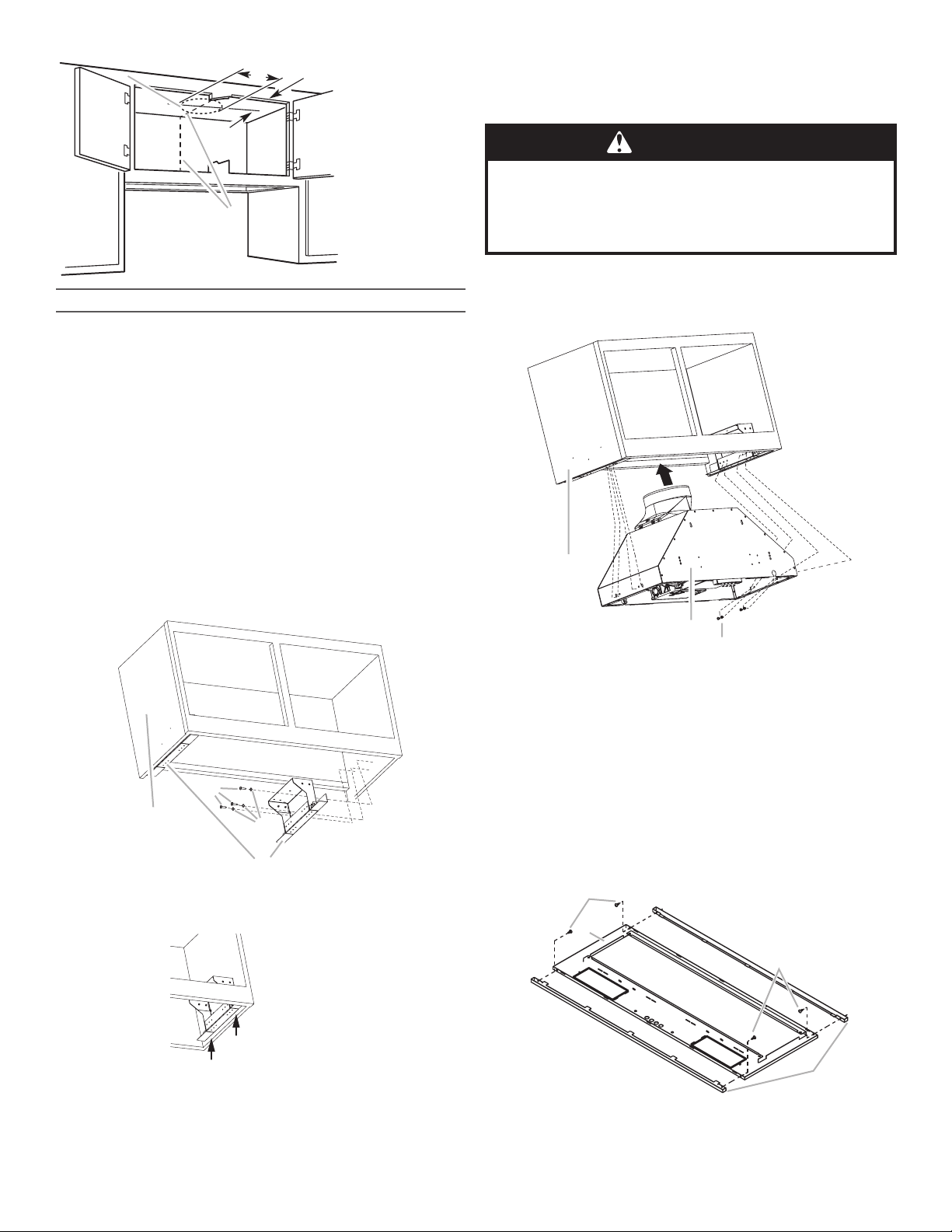
Complete Preparation
1. Ifnotyetattached,installthe6”(15.2cm)venttransitionthe
top of the range hood liner using two 3.5 x 9.5 mm screws.
2. Locatesidemountingbracketush1cmtothebottomofthe
cabinet side and against the inside of the front cabinet face.
Orient the bracket depending on the width of your cabinet as
depictedinthediagramsbelow.Drill⅛”(3mm)pilotholesin
6 places, attach a bracket using three 4.5 x 13 mm screws to
each side of the cabinet, and tighten. Additional washers in
hardware package are supplied as spacers for cabinet walls
thinnerthan½”(13mm).
BracketOrientationfor30”(76.2cm)Cabinet
A
B
C
D
A.30”(76.2cm)cabinet
B.Screws-4.5x13mm(8)
C.Washers(optional)
D.Mountingbracket(2)(positionfor30”[76.2cm]cabinet)
Move the bracket 6⁄16”(1cm)fromthebottom
side of the cabinet
3. Install the vent system according to the method needed.
Use caulking to seal the exterior wall or roof opening.
WARNING
Excessive Weight Hazard
Use two or more people to move and install
range hood.
Failure to do so can result in back or other injury.
1. Using 2 or more people, lift the hood liner into its mounted
location. Attach with four 4.2 x 19 mm screws into the slotted
openings. Do not tighten screws.
A
B
C
A.Cabinet
B.Hood liner canopy assembly C.Screws-4.2x19mm(8)
2. Center the canopy in the cabinet. Align the bottom of the
canopy with the bottom of the cabinet. Install four 4.2 x 19 mm
screws into the round mounting plate openings and tighten all
(8)mountingscrews.
3. Removethemetalgreaseltersfromthefacepanel.Seethe
“Range Hood Care” section.
Attach the face plate to the hood insert.
NOTE: If cabinet depth is greater than 12”, it is recommended
thatthetwo1/2”metalspacersareinstalled.
Install to front and rear sides of the face plate with 3.5 x 9.5
mm screws as shown in drawing.
C
A
C
B
A.Face Panel
B.Front and rear spacer C.Screws-3.5x9.5mm(4)
Install Range Hood

10
B
C
D
A
A.Screws-3.5x9.5mmflat-head(4)
B.Faceplate(30”x12”[76.2cmx30.5cm]shown)
C.Cabinet(30”x12”[76.2cmx30.5cm]shown)
D.Screws-4.2x15mmtruss-head(2)
For cabinet size - 30” x 12” (76.2 cm x 30.5 cm)
Attach the 281⁄4” x 10 ¾”(71.8cmx27.3cm)facepanel(supplied
withrangehood)tothehoodlinerusingfour3.5x9.5mm
at-headscrewsandtwo4.2x15mmtrussheadscrews.
Tighten to secure.
Connect the lamp electrical connector.
Connect the Vent System
Vented Installations
1. Connect the vent system to the range hood vent opening.
Seal the connection with clamps.
Non-Vented (recirculating) Installations
1. Connect the vent system to the range hood vent opening.
Seal the connection with clamps.
2. Installcharcoallters.Seethe“Availableaccesories”section.
Complete Installation
1. Replacegreaselters.Seethe“RangeHoodCare”section.
WARNING
Electrical Shock Hazard
Plug into a grounded 3 prong outlet.
Do not remove ground prong.
Do not use an adapter.
Do not use an extension cord.
Failure to follow these instructions can result in
death, re, or electrical shock.
2. Plug3-prongpowercordintoagrounded3-prongoutlet
located inside the cabinet above the range hood.
3. Check the operation of the range hood fan and light. See
“Range Hood Use” section.
If range hood does not operate, check to see whether a
circuit breaker has tripped or a household fuse has blown.
Disconnect power and check wiring connections.
NOTE:Togetthemostefcientusefromyournewrangehood,
read the “Range Hood Use” section.

11
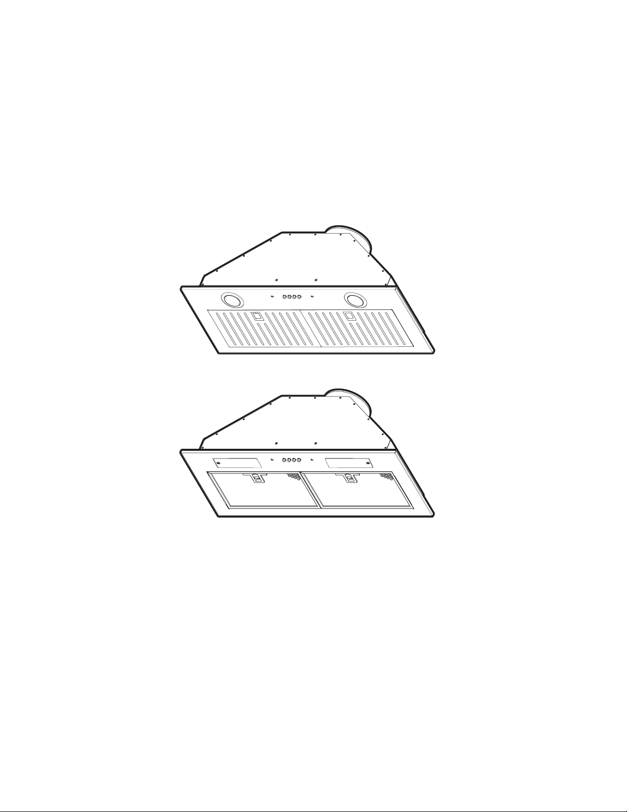
Range Hood Use
The range hood is designed to remove smoke, cooking vapors
and odors from the cooktop area. For best results, start the hood
before cooking and allow it to operate several minutes after the
cooking is complete to clear all smoke and odors from the
kitchen.
The hood controls are located on the center of the front of the
range hood liner.
D
C
A
B
A. Blower and light controls
B. Grease filter
C. Grease filter handle
D.HalogenorIncandescentlamps(dependingofhoodmodel)
Range Hood Controls
A B C D
A.On/Offlightbutton
B. Blower off and speed minimum button
C. Blower speed medium button
D. Blower speed maximum button
Operating the Light
TheOn/Offlightbuttoncontrolsalllights.PressonceforOnand
again for Off.
Operating the Blower
The BLOWER SPEED buttons turn the blower on and control the
blower speed and sound level for quiet operation. The speed can
be changed anytime during fan operation by pressing the desired
blower speed button.
Press the BLOWER OFF button a second time to turn off the
blower.
Range Hood Care
Range Hood Controls
IMPORTANT:Cleanthehoodandgreaseltersfrequently
accordingtothefollowinginstructions.Replacegreaselters
before operating hood.
Exterior Surfaces:
To avoid damage to the exterior surface, do not use steel wool or
soap-lledscouringpads.
Always wipe dry to avoid water marks.
Cleaning Method:
■ Liquiddetergentsoapandwater,orall-purposecleanser
■Wipe with damp soft cloth or nonabrasive sponge, then rinse
with clean water and wipe dry.
Metal Grease Filter
Theltersshouldbewashedfrequently.Placemetalltersin
dishwasher or hot detergent solution to clean.
Letlterdrythoroughlybeforereplacingit.
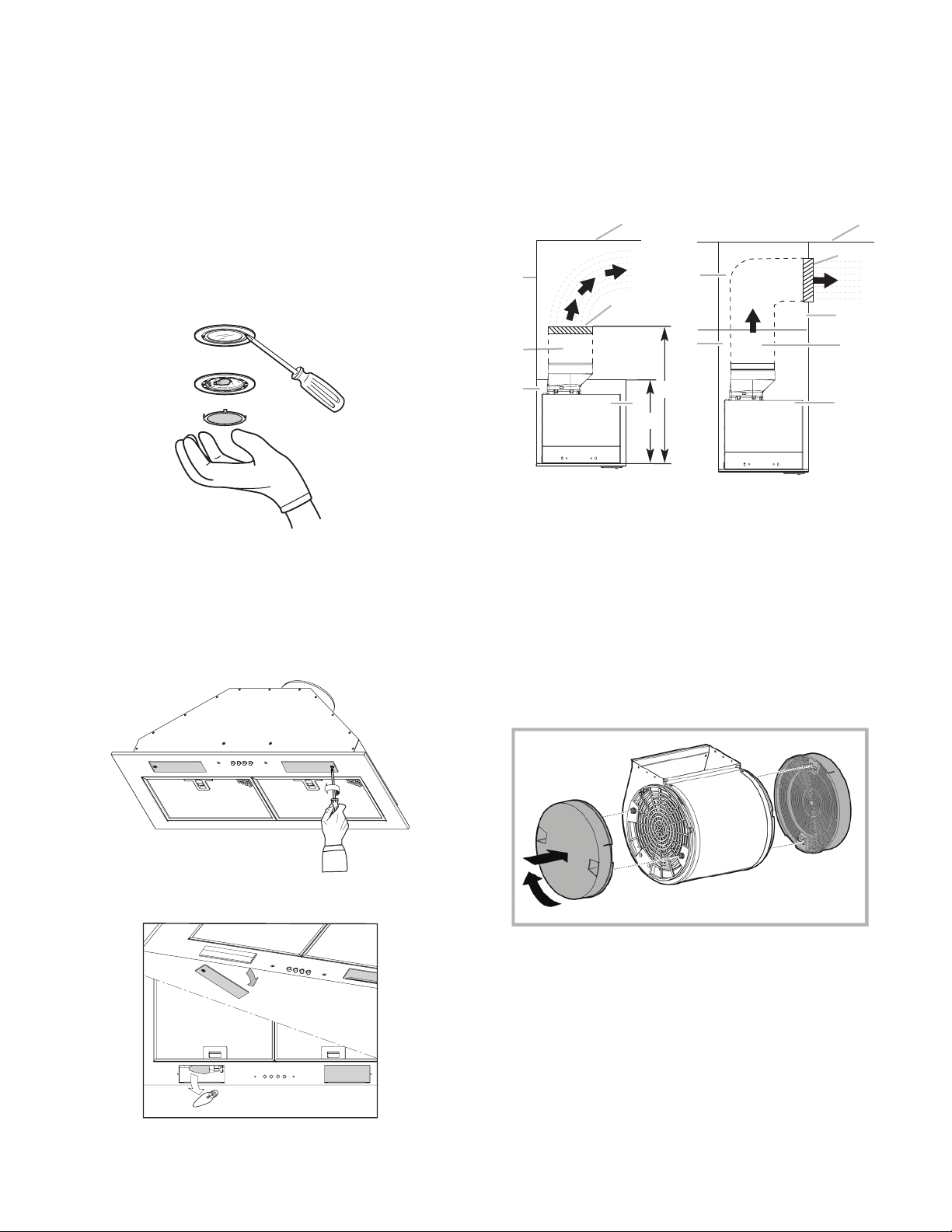
Turn off fan and lights. Allow lamps to cool.
1. Removeeachlterbypullingthespringreleasehandleand
thenpullingdownthelter.
A
A. EPR628SS model spring release handle
A
A. EAS428SS model Spring release handle
2. Washmetalltersasneededindishwasherorhotdetergent
solution.
3. Reinstallthelterbymakingsurethespringreleasehandles
aretowardthefront.Insertmetalgreaselterintoupper
track.
4. Pull the spring release handle down.
5. Pushuponmetallterandreleasehandletolatchintoplace.
6. Repeatsteps1-5fortheotherlter.
12
Replacing the halogen lamp (EPR628SS models)
CAUTION: Before replacing the lamps, disconnect power off
to prevent from being switched on accidentally.
Turnofftherangehoodandallowthehalogen/incandescent
lamp to cool. To avoid damage or decreasing the life of the new
bulb,donottouchbulbwithbarengers.Replacebulb,using
tissue or wearing cotton gloves to handle bulb.
If new lamps do not operate, make sure the lamps are inserted
correctly before calling service.
1. Disconnect power.
2. Useaat-bladescrewdriverandgentlyprythelightcover
loose.
3. Removethelampandreplacewitha120-volt,40-watt
maximum,halogenlampmadeforaG-9base.
4. Replace the light cover.
5. Reconnect power.
Replacing the incandescent lamps (EAS428SS models)
1. Disconnect power.
2. Use a Phillips # 2 screw driver to remove the lamp cover.
Remove it carefully from its housing.
3. Removethedamagedlampbulb(turncounterclockwise)and
replace it with a new bulb. E12 Philips Lamp 120V, 40W.
Reconnect power.
Available Accessories
Recirculating Kit
If it is not possible to vent cooking fumes and vapors to the
outside,therangehoodcanbeusedinthenon-vented
(recirculating)version,usingacharcoallter.RecirculationKit
model number EXXRCK10 is available from the dealer or an
authorized parts distributor.
E
A
B
G
D
F
H
I
A
B
G
F
C
D
E
A. Ceiling
B. Vent cover
C. Soffit
D.6”(15.2cm)vent
E. Range hood
F. Cabinet
G.Wall
H.12”(30.5cm)min.cabinetheight
I.17”(43.2cm)min.ventcoverheight
NOTE:12”(30.5cm)highcabinetswithoutasoftmayallowthe
6” vent and vent cover to be seen.
1. Cover the grill that protects the suction motor with the carbon
ltersothattheslotsontheltercorrespondtothepinson
the sides of the motor protection grill.
2. Turnthecarbonlterclockwisetoblockthem(bayonetxing).
NOTE:Thecharcoallterscannotbecleaned.Itshouldbe
replacedevery4-6months(dependingonhoodusage).
Extension Liner Kit
• 30” wide x 17” or 20” deep liner is available for both EAS428SS
and EPR628SS which provides complete protection of the
cabinets (modelnumberEXXHDL30).
• 36” wide x 17” or 20” deep liner is available for both EAS428SS
and EPR628SS which provides complete protection of the
cabinets(modelnumberEXXHDL36).
See Liner installation instructions for more detail.

13
WARRANTY
ELICA North America TWO-YEAR LIMITED WARRANTY
TO OBTAIN SERVICE UNDER WARRANTY
Ownermustpresentproofoforiginalpurchasedate.Pleasekeepacopyofyourdatedproofofpurchase(salesslip)inorderto
obtain service under warranty.
PARTS AND SERVICE WARRANTY
Fortheperiodoftwo(2)yearfromthedateoftheoriginalpurchase,Elicawillprovidefreeofcharge,nonconsumablepartsor
componentsthatfailedduetomanufacturingdefects.Duringthesetwo(2)yearlimitedwarranty,Elicawillalsoprovidefreeof
charge,alllaborandin-homeservicetoreplaceanydefectiveparts.
WHAT IS NOT COVERED
• DamageorfailuretotheproductcausedbyaccidentoractofGod,suchas,ood,reorearthquake.
• Damageorfailurecausedbymodicationoftheproductoruseofnon-genuineparts.
• Damage or failure to the product caused during delivery, handling or installation.
• Damage or failure to the product caused by operator abuse.
• Damage or failure to the product caused by dwelling fuse replacement or resetting of circuit breakers.
• Damage or failure caused by use of product in a commercial application.
• Service trips to dwelling to provide use or installation guidance.
• Lightbulbs,metalorcarbonltersandanyotherconsumablepart.
• Normalwearofnish.
• Weartonishduetooperatorabuse,impropermaintenance,useofcorrosiveorabrasivecleaningproducts/padsandoven
cleaner products.
WHO IS COVERED
ThiswarrantyisextendedtotheoriginalpurchaserforproductspurchasedforordinaryresidentialuseinNorthAmerica(Including
theUnitedStates,Guam,PuertoRico,USVirginIslands&Canada).
Thiswarrantyisnon-transferableandappliesonlytotheoriginalpurchaseranddoesnotextendtosubsequentownersofthe
product. This warranty is made expressly in lieu of all other warranties, expressed or implied, including, but not limited to any
impliedwarrantyofmerchantabilityortnessforaparticularpurposeandallotherobligationsonthepartofElicaNorthAmerica,
provided, however, that if the disclaimer of implied warranties is ineffective under applicable law, the duration of any implied
warrantyarisingbyoperationoflawshallbelimitedtotwo(2)yearfromthedateoforiginalpurchaseatretailorsuchlongerpe-
riod as may be required by applicable law.
Thiswarrantydoesnotcoveranyspecial,incidentaland/orconsequentialdamages,norlossofprots,sufferedbytheoriginal
purchaser,itscustomersand/ortheusersoftheProducts.
WHO TO CONTACT
To obtain service under warranty or for any service related question:
• ElicaNorthAmericaAuthorizedService-(714)428-0046
• elica@servicepower.com

14
APPROUVÉ POUR LES APPAREILS
DE TYPE RÉSIDENTIEL
POUR UNE UTILISATION
RÉSIDENTIELLE SEULEMENT
LISEZ CES INSTRUCTIONS ET CONSERVEZ-LES
VEUILLEZ LIRE CES INSTRUCTIONS AU COMPLET AVANT
DE COMMENCER. L’INSTALLATION DE L’APPAREIL DOIT
RESPECTER TOUS LES CODES EN VIGUEUR.
IMPORTANT: Conservezcesinstructionsandepouvoirles
remettreàl’inspecteur-électriciendevotrerégion.
INSTALLATEUR: Veuillez laisser ces instructions avec l’appareil
pour le propriétaire.
PROPRIÉTAIRE: Veuillez conserver ces instructions pour pouvoir
vous y référer plus tard.
Avertissement de sécurité:Coupez l’alimentation du circuit
dans le panneau électrique et verrouillez le panneau avant de
raccorderleslsdecetappareil.
Exigence: 120V c.a., 60Hz circuit de dérivation de 15V c.a., 20Hz, de 15
ou 20A.
AVERTISSEMENT: POUR RÉDUIRE LE RISQUE
D’INCENDIE, CHOC ÉLECTRIQUE OU DOMMAGES
CORPORELS, RESPECTER LES INSTRUCTIONS
SUIVANTES:
■Utilisercetappareiluniquementdanslesapplicationsenvisa-
gées par le fabricant. Pour toute question, contacter le fabricant.
■Avant d’entreprendre un travail d’entretien ou de nettoyage,
interrompre l’alimentation de la hotte au niveau du tableau
de disjoncteurs, et verrouiller le tableau de disjoncteurs pour
empêcher tout rétablissement accidentel de l’alimentation du
circuit. Lorsqu’il n’est pas possible de verrouiller le tableau de
disjoncteurs, placer sur le tableau de disjoncteurs une
étiquette d’avertissement proéminente interdisant le
rétablissement de l’alimentation.
■Tout travail d’installation ou câblage électrique doit être réalisé
parunepersonnequaliée,danslerespectdesprescriptions
de tous les codes et normes applicables, y compris les codes
du bâtiment et de protection contre les incendies.
■Ne pas faire fonctionner un ventilateur dont le cordon ou la
cheestendommagé(e).Jeterleventilateurouleretourner
àuncentredeserviceagréépourexamenet/ouréparation.
■Unesourced’airdedébitsufsantestnécessairepourle
fonctionnementcorrectdetoutappareilàgaz(combustion
etévacuationdesgazàcombustionparlacheminée),pour
qu’iln’yaitpasdereuxdesgazdecombustion.Respecter
les directives du fabricant de l’équipement de chauffage et
lesprescriptionsdesnormesdesécurité-commecelles
publiéesparlaNationalFireProtectionAssociation(NFPA)
et l’American Society for Heating, Refrigeration and Air
ConditioningEngineers(ASHRAE),etlesprescriptionsdes
autorités réglementaires locales.
■Lors d’opérations de découpage et de perçage dans un mur
ou un plafond, veiller à ne pas endommager les câblages éle
ctriques ou canalisations qui peuvent s’y trouver.
■Les ventilateurs d’évacuation doivent toujours décharger
l’air à l’extérieur.
MISE EN GARDE: Cet appareil est conçu uniquement
pour la ventilation générale. Ne pas l’utiliser pour l’extraction
de matières ou vapeurs dangereuses ou explosives.
MISE EN GARDE: Pour minimiser le risque d’incendie et
évacuer adéquatement les gaz, veiller à acheminer l’air
aspiréparunconduitjusqu’àl’extérieur-nepasdécharger
l’air aspiré dans un espace vide du bâtiment comme une
cavité murale, un plafond, un grenier, un vide sanitaire ou
un garage.
AVERTISSEMENT: POUR RÉDUIRE LE RISQUE D’INCENDIE,
UTILISER UNIQUEMENT DES CONDUITS MÉTALLIQUES.
AVERTISSEMENT: POUR MINIMISER LE RISQUE D’UN FEU
DE GRAISSE SUR LA CUISINIÈRE:
■Ne jamais laisser un élément de surface fonctionner à
puissance de chauffage maximale sans surveillance.
Unrenversement/débordementdematièregraisseusepourrait
provoqueruneinammationetlagénérationdefumée.Utiliser
une puissance de chauffage moyenne ou basse pour le
chauffage d’huile.
■Veiller à toujours faire fonctionner le ventilateur de la hotte
lors de la cuisson avec une puissance de chauffage élevée ou
lorsdelacuissond’unmetsàamber(àsavoircrêpes
Suzette,cerisejubilée,steakaupoivreambé).
■Nettoyer fréquemment les ventilateurs d’extraction. Veiller à
nepaslaisserlagraisses’accumulersurlessurfacesduventi-
lateuroudesltres.
■Utilisertoujoursunustensiledetailleappropriée.Utilisertou-
jours un ustensile adapté à la taille del’ élément chauffant.
AVERTISSEMENT : POUR RÉDUIRE LE RISQUE DE
DOMMAGES CORPORELS APRÈS LE DÉCLENCHEMENT
D’UN FEU DE GRAISSE SUR LA CUISINIÈRE, APPLIQUER LES
RECOMMANDATIONS SUIVANTES:a
■Placer sur le récipient un couvercle bien ajusté, une tôle à
biscuits ou un plateau métallique POUR ÉTOUFFER LES
FLAMMES, puis éteindre le brûleur. VEILLER À ÉVITER LES
BRÛLURES.Silesammesnes’éteignentpasimmédiate-
ment, ÉVACUER LA PIÈCE ET APPELER LES POMPIERS.
■NEJAMAISPRENDREENMAINUNRÉCIPIENTENFLAM-
MÉ-vousrisquezdevousbrûler.
■NEPASUTILISERD’EAU,niuntorchonhumide-ceci
pourrait provoquer une explosion de vapeur brûlante.
IMPORTANTES INSTRUCTIONS DE SÉCURITÉ
Table des matières
Importantes instructions de sécurité......................................14
Outils et pièces......................................................................... 15
Exigences d’emplacement ..................................................15
Dimensions du produit ........................................................16
Exigences concernant l’évacuation.....................................16
Méthodes d’évacuation ...................................................... 17
Calcul de la longueur effective du circuit d’évacuation........17
Spécications électriques........................................................17
Instructions d’installation ....................................................... 18
Préparation de l’emplacement.............................................18
Installation de la hotte..............................................................20
Raccordement du circuit d’évacuation.................................21
Achever l’installation............................................................21
Utilisation de la hotte................................................................22
Entretien de la hotte..................................................................22
Accessoires...............................................................................23
Garantie..................................................................................... 24

15
Outils et pièces
Rassembler les outils et pièces nécessaires avant d’entreprendre
l’installation. Lire et observer les instructions fournies avec
chacundesoutilsdelalisteci-dessous.
Outils nécessaires
■Niveau
■Perceuse
■ Foretde1⁄8”(3mm)
■Crayon
■Pince
■ Mètre-rubanourègle
■Pistolet à calfeutrage et composé de calfeutrage résistant
aux intempéries
■Tournevis Phillips
■Tournevis à lame plate
■Scie sauteuse ou scie à guichet
■Brides de conduit
■Cisaille de ferblantier
Pièces fournies
Retirerlespiècesdeleuremballage.Vérierquetoutesles
pièces sont présentes.
■ 1-panneaudesurfacede30”x12”(76,2x30,5cm)
■Racord de transition
■ 2-Lampesàincandescencedu40W(modèleEAS428SS
seulement)
■ 2-Lampesàhalogènedu50W(modèleEPR628SS
seulement)
■ 2-Filtresàgraissemétalliques
■ 2-Bridesdemontage
■ 2-barresd’espacement(pouruneutilisationlorsquela
profondeurdelcabinetestsupérieureà12“)
■Sachet de quincaillerie. Comprend :
• Instructions d’installation et Guide d’utilisation et d’entretien
• 8-rondellesmétalliques
• 8-rondellesenplastique
• 8-vis de à bois de 4,5 x 13 mm
• 2-vis de tôlerie de 4,2 x 15 mm
• 4-vis de tôlerie à tête plate de 3,5 x 9,5 mm
• 8-vis de tôlerie de 4,2 x 19 mm
• 6-vis de tôlerie de 3,5 x 9,5 mm
• Adaptateur T10 TORX®
Pièces nécessaires
■Système de conduit d’évacuation métallique rond de 6”
(15,2cm)
Exigences d’emplacement
IMPORTANT : Observer les dispositions de tous les codes et
règlements en vigueur.
Conerl’installationdelahotteàuntechnicienqualié.C’està
l’installateur qu’incombe la responsabilité de respecter les
distancesdeséparationexigées,spéciéessurlaplaque
signalétique de l’appareil. La plaque signalétique de l’appareil est
situéederrièreleltre,surlaparoiarrièregauchedelahotte.
Installer la hotte de cuisinière à distance de toute zone exposée à
des courants d’air, comme fenêtres, portes et bouches de
chauffage.
Respecter les dimensions indiquées pour les ouvertures à
découper dans les placards. Ces dimensions tiennent compte
des valeurs minimales des dégagements de séparation. Avant
d’effectuer des découpages, consulter les instructions
d’installationdelatabledecuisson/cuisinière.
On doit disposer d’une prise de courant électrique reliée à la
terre.Voirlasection“Spécicationsélectriques”.
Lahotteaétéconguréeàl’usinepouruneinstallationavec
décharge à l’extérieur à travers le toit ou le mur. Pour une
installationsansdéchargeàl’extérieur(recyclage),voir
“Installationsansdéchargeàl’extérieur(recyclage)àtraversle
softe/placard”,àlasection“Préparationdel’emplacement”.
Ensembledeltresàcharbon(piècenuméroW10272068)est
disponible chez votre marchand ou chez un distributeur de
pièces autorisé.
Assurer l’étanchéité au niveau de chaque ouverture découpée
dans le plafond ou le mur pour l’installation de la hotte de
cuisinière.
Installation dans une résidence mobile
L’installation de cette hotte doit satisfaire aux exigences de la
norme Manufactured Home Construction Safety Standards, Titre
24CFR,partie328(anciennementFederalStandardforMobile
HomeConstructionandSafety,titre24,HUD,partie280);lorsque
cette norme n’est pas applicable, l’installation doit satisfaire aux
critères de la plus récente édition de la norme Manufactured
HomeInstallation1982(ManufacturedHomeSites,Communities
andSetups)ANSIA225.1/NFPA501A,oudescodeslocaux.
†®TORX est une marque déposée de Saturn Fasteners, Inc.
■Utiliser un extincteur SEULEMENT si :
– Il s’agit d’un extincteur de classe ABC, dont on connaît le
fonctionnement.
– Il s’agit d’un petit feu encore limité à l’endroit où il s’est
déclaré.
– Les pompiers ont été contactés.
– Il est possible de garder le dos orienté vers une sortie
pendant l’opération de lutte contre le feu.
aRecommandations tirées des conseils de sécurité en cas
d’incendie de cuisine publiés par la NFPA.
AVERTISSEMENT : Pour réduire le risque d’incendie
ou de choc électrique, ne pas utiliser ce ventilateur avec un quel-
conque dispositif de réglage de la vitesse à semiconducteurs.

16
Dimensions du produit
I*
I*
I*-Barresd’espacement
Pour une utilisation lorsque
la profondeur del cabinet est
supérieure à 12 “.
Hotte de la cuisiniere modéles EAS428SS / EPR628SS
Dimension
DIM A 28”(71.8cm)
DIM B 26”(66cm)
DIM C 1⅛”(2.9cm)
DIM D 10¾”(27.3cm)
DIM E 9½”(24.2cm)
DIM F 5⁄16”(.85cm)
DIM G 14 9⁄16”(37cm)
DIM H 6”(14.8cm)
DIM I ½”(1.27cm)
Dimensions du placard
A. Hauteur minimale de placard 12”
(30,5cm)
B. Largeur de l’ouverture de
placard30”(76,2cm)min.
C.24”(61cm)min.àpartirdela
surface de cuisson électrique,
27”(68,6cm)min.àpartirdela
surface de cuisson au gaz;
distance max. suggérée de 36”
(91,4cm)entrelebasdu
placard et la surface de cuisson.
D. Profondeur de placard de
12”(30,5cm)
E. Dégagement min. entre le haut
du placard et le plan de travail
de15”(38,1cm)
F. Hauteur de placard sur plancher
de36”(91,4cm)
Pour l’installation a partir de la surface de cuisson electrique:
Monter cette hotte de sorte que le bord inférieur est au minimum
de27“(68,5cm)au-dessusdelasurfacedecuisson.
Pour l’installation a partir de la surface de cuisson au gaz: monter
cettehottepourquelefondn’estpasinférieurà24“(61cm).
*REMARQUE:Cettehotteestxéà30“(76,2cm)largeurd’ar-
moirex12”(30,5cm)armoiresprofondes.
EXIGENCES CONCERNANT L’ÉVACUATION
■Le circuit d’évacuation doit décharger l’air à l’extérieur,
excepté pour les installations sans décharge à l’extérieur
(recyclage).
■Ne pas terminer le circuit d’évacuation dans un grenier ou
dans un autre espace clos.
■ Nepasutiliserunebouchededéchargemuralede4”(10,2
cm)normalementutiliséepourunéquipementdebuanderie.
■Utiliser un conduit métallique uniquement. Un conduit en
métal rigide est recommandé. Ne pas utiliser de conduit de
plastique ou en aluminium.
■La longueur du conduit de décharge et le nombre de coudes
doivent être réduits au minimum pour fournir la meilleure
performance.
Pourunfonctionnementefcaceetsilencieux:
■Ne pas utiliser plus de trois coudes à 90°.
■Veiller à ce qu’il y ait une section droite de conduit d’un
minimumde24”(61cm)entrelesraccordscoudés,siondoit
en utiliser plus d’un.
■Ne pas installer 2 coudes successifs.
■ Lecircuitd’évacuationdoitcomporterunclapetanti-reux.
■Au niveau de chaque jointure du circuit d’évacuation, assurer
l’étanchéité avec les brides de serrage.
■À l’aide d’un produit de calfeutrage, assurer l’étanchéité
autourdelabouchededéchargeàl’extérieur(àtraversle
murouletoit).
■La taille du conduit doit être uniforme.
Installations pour régions à climat froid
Ondoitinstallerunclapetanti-retoursupplémentaireàl’arrière
pourminimiserlereuxd’airfroidetincorporerunélément
d’isolation thermique pour minimiser la conduction de chaleur
par l’intermédiaire du conduit d’évacuation, de l’intérieur de la
maisonàl’extérieur.Leclapetanti-retourdoitêtreplacéducôté
air froid de la résistance thermique.
Air d’appoint
Les codes du bâtiment locaux peuvent exiger l’emploi d’un
systèmederenouvellementdel’air/introductiond’aird’appoint,
lors de l’utilisation d’un système d’aspiration de débit supérieur à
unevaleur(piedscubesparminute)spéciée.Ledébitspécié
en pieds cubes par minute varie d’une juridiction à l’autre.
Consulter un professionnel des installations de chauffage
ventilation/climatisationausujetdesexigencesspéciques
applicables dans la juridiction locale.

17
Méthodes d’évacuation
Cettehotteaétéconguréeàl’usinepourladéchargeàtravers
le toit ou à travers le mur.
Le système de décharge requis pour l’installation n’est pas
fourni.Uncircuitd’évacuationavecconduitcirculairede6”(15,2
cm)estrecommandé.
Décharge à
travers le toit
A.Conduitdedia.6”(15,2
cm)pourdéchargeà
travers le toit
B. Bouche de décharge
sur toit
Évacuation par le
mur
A.Conduitdedia.6”(15,2
cm)pourdéchargeà
travers le mur
B. Bouche de décharge
murale
Recyclage
A.Conduitdedia.6”(15,2
cm)pourdéchargeà
travers le placard
B. Grille de recirculation
rond
Calcul de la longueur effective du circuit d’évacuation
Pour la réalisation du circuit d’évacuation, on recommande un
conduitde6”(15,2cm)dediamètreavecunelongueurmaximale
de35pi(10,7m).Pouruneperformanceoptimale,nepasutiliser
plus de trois coudes à 90°.
Pour calculer la longueur effective du circuit d’évacuation
nécessaire,additionnerleslongueurséquivalentes(enpieds/
mètres)detouslescomposantsutilisésdanslecircuit.
Composant 6” (15.2 cm)
Coude à 45° 2,5 pi
(0,8m)
Coude à 90° 5,0 pi
(1,5m)
Exemple de circuit d’évacuation - 6” (15,2 cm)
coude à 90° Bouche de décharge murale
2pi(0.6m)
6pi(1.8m)
Longueur maximum = 35 pi (10,7 m)
1-Coude à 90° =5.0pi(1.5m)
1-Bouchededécharge =0.0pi(0.0m)
9pi(2.8m)droit =9.0pi(2.4m)
Longueur totale = 14.0 pi (3.9 m)
AVERTISSEMENT
Brancher sur une prise à 3 alvéoles reliée à la terre.
Ne pas enlever la broche de liaison à la terre.
Ne pas utiliser un adaptateur.
Ne pas utiliser un câble de rallonge.
Le non-respect de ces instructions peut causer
un décès, un incendie ou un choc électrique.
IMPORTANT: La hotte doit être correctement reliée à la terre en
conformité avec les codes et règlements locaux en vigueur, ou en
l’absencedetelscodes,avecleNationalElectricalCode,ANSI/
NFPA70(dernièreédition)ouleCodecanadiendesinstallations
électriques,CSAC22.1.No.0-M91(dernièreédition).
Si les codes le permettent et si on utilise un conducteur distinct
deliaisonàlaterre,ilestrecommandéqu’unélectricienqualié
vérielaqualitédelaliaisonàlaterre.
Spécications électriques
Pourobtenirunexemplairedesnormesdescodesci-dessus,
contacter :
National Fire Protection Association
1 Batterymarch Park
Quincy,MA02169-7471
CSA International
8501 East Pleasant Valley Road
Cleveland,Ohio44131-5575
■Une alimentation de 120 volts, 60 Hz, CA seulement, de
15 ou 20 ampères, protégée par un fusible est requise. On
recommande également d’utiliser un fusible ou un disjoncteur
temporisé. Il est recommandé de raccorder la hotte sur un
circuit distinct exclusif à cet appareil.
■Cette hotte est équipée d’un cordon d’alimentation électrique
de liaison à la terre à trois broches.
■Pour minimiser les risques de choc électrique, on doit
brancherlecordonsuruneprisedecourantdeconguration
correspondante, à 3 alvéoles, reliée à la terre et installée
conformément aux codes et règlements locaux. Si une prise
de courant de conguration correspondante n’est pas
disponible, le client a la responsabilité et l’obligation de faire
installer par un électricien qualié une prise de courant
correctement reliée à la terre.

18
Instructions d’Installation
Préparation de l’emplacement
■Il est recommandé que l’installation du circuit d’évacuation
soit réalisée avant celle de la hotte.
■ Avantdeprocéderauxdécoupages,vérierquelesdistances
de séparation pour les raccords dans les cavités du plafond
ou du mur sont adéquates.
■ Avantdemonterleplacardaumur,ilserapeut-êtreplusfacile
de découper au préalable l’ouverture dans le fond du placard.
1. Déconnecter la source de courant électrique.
2. Déterminer la méthode d’évacuation à utiliser : décharge à
travers le mur ou le toit, ou recyclage.
3. Choisir une surface plane pour l’assemblage de la hotte.
Placer le matériau de protection sur cette surface.
AVERTISSEMENT
Risque du poids excessif
Utiliser deux ou plus de personnes pour déplacer
et installer la hotte de la cuisinière.
Le non-respect de cette instruction peut causer
une blessure au dos ou d’autre blessure.
4. À l’aide de deux personnes ou plus, soulever la hotte et la
poser sur la surface couverte.
Ouverture découpée du placard pour la hotte
1. Utiliser une scie sauteuse ou scie à guichet pour découper
une ouverture dans le fond du placard, à l’intérieur du cadre
du placard.
REMARQUE: Pour les placards sans cadres, un rebord
avantetarrièrede¾”(1,9cm)estnécessairepourformerun
cadre dans le fond du placard. Une tringle d’appui de ¾”
(1,9cm)d’épaisseur(nonfournie)serapeut-êtrenécessaire
pour certains types de placards.
Ouverture dimensions (sans barres d’espacement)
261⁄8”(66.3cm)
107⁄8”
(27.62cm)
3⁄4”
(1.9cm)
1⁄2”
(1.27cm)
A. Ouverture dans le fond du placard
2. Terminer la préparation du placard conformément aux
instructions correspondant au type d’évacuation du domicile.
Déterminer l’emplacement des ouvertures d’aération et
découperlesouverturesdanslesplacards,lesmurset/oules
softes.
■La prise à 3 broches reliée à la terre doit se trouver dans un
placardsituéau-dessusdelahotte,àunedistancemaximale
de 337⁄16” (85,0 cm) à partir du point duquel le cordon
d’alimentation sort de la hotte. La prise à 3 broches reliée à la
terre doit être accessible une fois la hotte installée. Voir
l’illustration.
337⁄16”(85cm)
INSTRUCTIONS DE MISE À LA TERRE
■Pourunehottereliéeàlaterreetconnectéeparuncordon:
Cette hotte doit être reliée à la terre. Au cas où un courtcircuit
se produirait, la liaison à la terre réduit le risque de
choc électrique, en permettant au courant de s’échapper
directement vers la terre. La hotte est équipée d’un cordon
comportantunconducteurdeliaisonàlaterreavecchede
liaisonàlaterre.Lachedoitêtrebranchéedansuneprise
correctement installée et reliée à la terre.
AVERTISSEMENT: Une mise à la terre incorrecte peut en-
traîner un risque de choc électrique.
Consulterunélectricienqualiésilesinstructionsdemiseà
la terre ne sont pas complètement comprises, ou si vous
avez des doutes quant à la qualité de la liaison à la terre de
la hotte. Ne pas utiliser de câble de rallonge. Si le cordon
d’alimentation électrique est trop court, faire installer une
priseprèsdelahotteparunélectricienqualié.
CONSERVEZ CES INSTRUCTIONS
19
Décharge à l’extérieur, à travers le toit
1. Relever les mesures appropriées et tracer les lignes indiquées
sur l’illustration. Utiliser une scie sauteuse ou une scie à
guichet pour découper une ouverture à travers le sommet du
placard et le toit pour l’évacuation.
A
B* C
D
A. Ouverture
B.6¼”(15,9cm)*
C.7³⁄4”(19,7cm)entrel’axecentraletl’avantduplacard
D. Axe central
*REMARQUE:Pourlesplacardsd’unehauteurde12”(30,5cm),
une ouverture rectangulaire de 6¼” de profondeur x 8” de largeur
(14,6cmx20,3cm)danslesommetduplacardestobligatoire
pour établir le dégagement nécessaire au raccord de transition du
clapetanti-reux.
Décharge à l’extérieur, à travers le mur
1. Fixerleraccorddetransitionduconduitde6”(15,2cm)au
sommet de la caisse de la hotte à l’aide de deux vis de 3,5 x
9,5 mm. Assembler le conduit d’évacuation qui sera utilisé sur
leraccorddetransitionduconduitde6”(15,2cm).
2. Mesurer la distance entre le bas de la caisse de la hotte et
l’axecentralhorizontaldel’ouvertured’évacuation(A).
A
B
C
A. Mesure A
B. Axe central horizontal de l’ouverture
d’évacuation
C. Caisse de la hotte
3. Retirer le conduit d’évacuation de la caisse de la hotte.
Reporter la dimension A sur la paroi arrière du placard.
Prendre les mesures à partir de la face inférieure du placard.
4. Marquer le périmètre de l’ouverture à découper – voir
l’illustration. Utiliser une scie sauteuse ou une scie à guichet
pour découper une ouverture circulaire à travers l’arrière du
placard et le mur extérieur pour l’évacuation.
A
B
C
A. Mesure A
B. Axe central
C. Ouverture découpée
circulairede6¼”(15,9cm)
Installation sans décharge à l’extérieur (recyclage) à
travers le softe/placard
E
A
B
G
D
F
H
I
A
B
G
F
C
D
E
A. Plafond
B.Cache-conduit
C. Soffite
D.Éventde6”(15,2cm)
E. Hotte de cuisinière
F. Placard
G. Mur
H.Hauteurduplacardde12”(30,5cm)
I.Hauteurdecache-conduitde
17”(43,2cm)
1. Relever les mesures appropriées et tracer l’axe central d
placardjusqu’ausoftesituéau-dessus.
2. Mesurer la distance entre le bas du placard et l’axe central,
aupointoùleconduitd’évacuationressortdusofte.
Indiquer l’emplacement et utiliser une scie sauteuse ou scie à
guichetpourdécouperuntroude5¾”(14,6cm)pourle
cache-conduit.
AB
A.Cache-conduit
B. Axe central
*REMARQUE:Pourlesplacardsd’unehauteurde12”(30,5cm),
une ouverture rectangulaire de 6¼” de profondeur x 8” de largeur
(14,6cmx20,3cm)danslesommetduplacardestobligatoire
pour établir le dégagement nécessaire au raccord de transition du
clapetanti-reux

20
3. Relever les mesures appropriées et tracer l’axe central
del’ouverture, dans le sommet du placard. Utiliser une scie
sauteuse ou scie à guichet pour découper une ouverture pour
le passage du conduit d’évacuation.
ABC
D
A. Ouverture
B.Voirletableauci-des-
sous.
C.7³⁄4”(19,7cm)entre
l’axe central et l’avant du
placard
D. Axe central
Hauteur du
placard
Taille et forme du trou
12”(30,5cm) Une ouverture rectangulaire de 6¼” de profond-
eurx8”delargeur(15,9cmx20,3cm)dansle
sommet du placard est obligatoire pour établir le
dégagementnécessaireauclapetanti-reux.
Achever la préparation
1. S’iln’estpasencorexé,installerleraccorddetransitionde
6”(15,2cm)ausommetdelacaissedelahotteàl’aidede
deux vis T10 de 3,5 x 9,5 mm.
2. Repérer l’emplacement de la bride latérale de montage, en
afeurementaveclebasdelaparoilatéraleduplacardet
contre l’intérieur de la face avant du placard. Orienter la bride
tel qu’indiqué dans l’illustration suivante. Percer des avan
trous de ⅛”(3mm)en8pointsdifférentsetxerunebrideà
l’aide de quatre vis Phillips n°2 de 4,5 x 13 mm de chaque
côtéduplacard-serrerensuite.Lesachetdematériel
comporte des rondelles supplémentaires en plastique qui
peuvent être utilisées comme cales si l’épaisseur des parois
duplacardestinférieureཔ(13mm).
Orientationdelabridepourunplacardde30”(76,2cm)
A.Placardde30”(76,2cm)
B. 8 vis Phillips n°2 de 4,5 x 13 mm
C.Rondellesmétalliques(facultatives)
D.2bridesdemontage(positionpourun
placardde30”[76,2cm])
A
B
C
D
Déplacer le support 1 cm du fond
côté de l’armoire
3. Installer le circuit d’évacuation selon la méthode requise.
Utiliser un calfeutrant pour assurer l’étanchéité au point de
traversée du mur extérieur ou du toit.
Installation de la hotte
AVERTISSEMENT
Risque du poids excessif
Utiliser deux ou plus de personnes pour déplacer
et installer la hotte de la cuisinière.
Le non-respect de cette instruction peut causer
une blessure au dos ou d’autre blessure.
1. À l’aide d’au moins 2 personnes, soulever la caisse de la
hotteetl’installer.Laxerdanslesencochesenformede
trou de serrure à l’aide de quatre vis Phillips n°2 de 4,2 x
19 mm. Ne pas serrer les vis.
A. Placard
B. Auvent de la hotte
C. 8 vis de 4,2 x 19 mm
A
B
C
2. Au besoin, insérer 1 à 3 cales de chaque côté de l’auvent et
de la plaque de montage pour permettre le dégagement
nécessaire et centrer l’auvent dans le placard. Aligner la base
de l’auvent avec le bas du placard. Installer quatre vis Phillips
n°2 de 4,2 x 19 mm dans les trous de la plaque de montage
et serrer les 8 vis de montage.
3. Ôterlesltresàgraissemétalliquesdupanneauavant.Voirla
section “Entretien de la hotte”.
Fixer le panneau à la caisse de la hotte.
REMARQUE: Si la profondeur de l’armoire est supérieur à
12“,ilestrecommandéquelesdeux1/2“entretoises
métalliques sont installés.
Installez de faces et arrière del panneau avec 3,5 x 9,5
vis mm, comme illustré dans dessin.
C
A
C
B
A. Panneau
B. Barre de spacement
C.vis-3.5x9.5mm(4)
This manual suits for next models
2
Table of contents
Languages:
Other Elisa Ventilation Hood manuals

Popular Ventilation Hood manuals by other brands


Pelgrim
Pelgrim BSS670RVS Instructions for use

Pelgrim
Pelgrim BKE951RVS Instructions for use

Baumatic
Baumatic BEO910BGL instruction manual

Rubine
Rubine RCH-ASPIRA-90SS user manual

James
James KAVEZ 60 INOX Manual for the installation, use and maintenance

Cata
Cata GT-Plus Manual for the installation, use and maintenance


