Elite Fitness IT 9600-E User manual
1
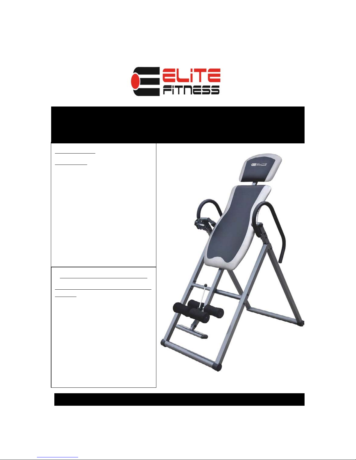
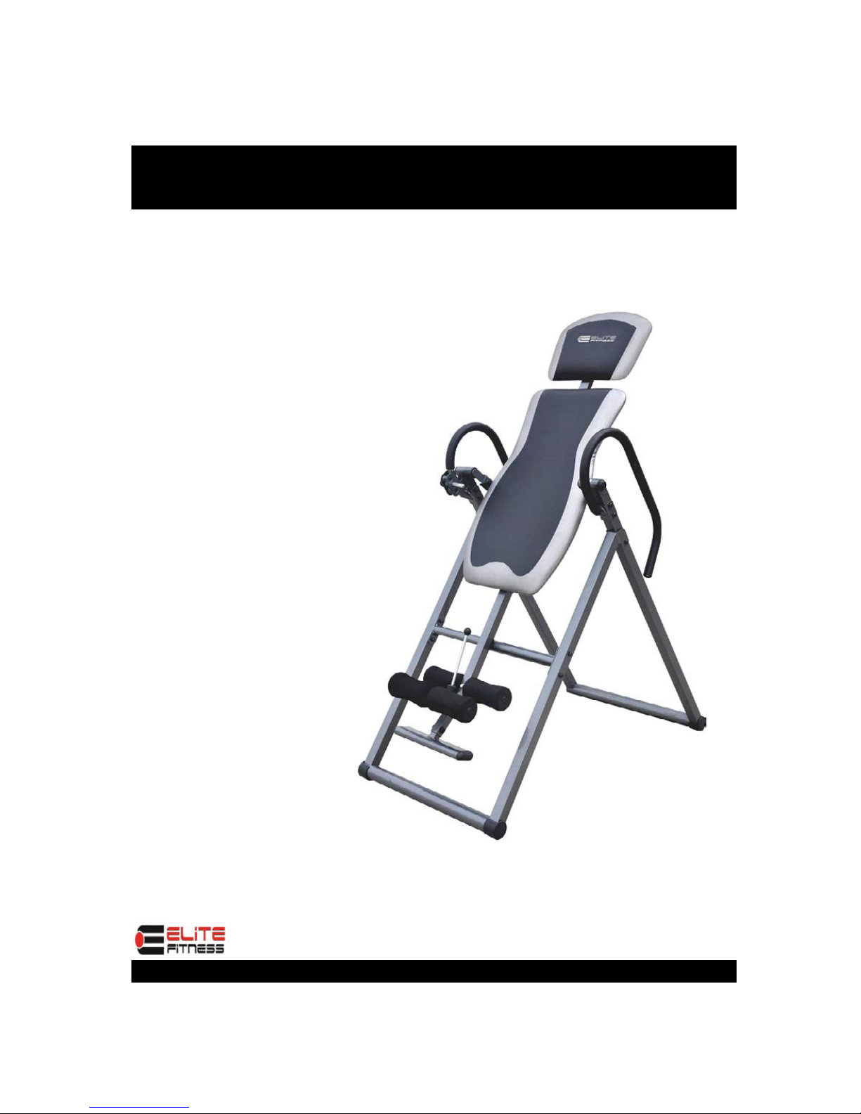
Deluxe Inversion Table
Model IT 9600-E
Owner’s Manual
Photo may differ from actual product
CAUTION:
CAUTION:
CAUTION:
CAUTION:
WARNING:
WARNING:
WARNING:
WARNING: Do not use this
Do not u se this
Do not use this
Do not use this
inversion table without a
inversion table without a
inversion table without a
inversion table without a
physician
physician
physician
physician’
’
’
’s approval.
s approva l.
s approval.
s approval.
Do not let children use the
Do not let children use the
Do not let children use the
Do not let children use the
inversion table unsupervised.
inversion table unsupervised.
inversion table unsupervised.
inversion table unsupervised.
Read all instructions carefully
Read all instructions carefully
Read all instructions carefully
Read all instructions carefully
before using.
before using.
before using.
before using.
Tighten all bolts before using
Tighten all bolts before using
Tighten all bolts before using
Tighten all bolts before using
equipment.
equipment.
equipment.
equipment.
Leave adequate space to
Leave adequate space to
Leave adequate space to
Leave adequate space to
properly invert.
properly invert.
properly invert.
properly invert.
.
Questions/ Comments
Questions/ Comments
Questions/ Comments
Questions/ Comments
PLEASE DO NOT CONTACT THE
PLEASE DO NOT CONTACT THE
PLEASE DO NOT CONTACT THE
PLEASE DO NOT CONTACT THE
STORE
STORE
STORE
STORE
Elite Fitness is committed to
providing the very best of quality
and customer satisfaction for all of
the products we distribute. If for
any reason , you are dissatisfied
with the product you have
purchased or need assistance in
any way, please do not hesitate to
contact our knowledgeable support
staff at: 623-888-6379
Mon.-Fri 9:00 am – 5:00 pm Mountain Time

2
BEFORE BEGINNING ASSEMBLY…
Take a few moments to familiarize yourself with the specific parts and hardware included with your
product. Make sure all the parts and hardware are included in the carton and examine them for any
damage that may have occurred in transport. Some parts may be pre-assembled and pre-installed.
CAUTION
CAUTION
CAUTION
CAUTION
WARNING:
WARNING:
WARNING:
WARNING:
Before starting any exercise program, consult your physician.
Read all instructions very carefully before using equipment
Tighten all bolts securely before using equipment
Product Warranty
Product Warranty
Product Warranty
Product Warranty
Limited Liability
Elite Fitness warrants that this product will be free from defects in materials and workmanship for a period
of ninety ( 90 ) days from date of purchase. This warranty applies only to the original purchaser when
purchase of the product is from an authorized retailer and is for personal or household use, but not when
the sale is for commercial use. This warranty is not transferable.
EXCEPT FOR THE LIMITED EXPRESS WARRANTY STATED HEREIN, Elite Fitness DISCLAIMS ALL
OTHER EXPRESS OR IMPLIED WARRANTIES, INCLUDING BUT NOT LIMITED TO IMPLIED
WARRANTIES OF MERCHANTABILITY AND FITNESS FOR A PARTICULAR PURPOSE. SOME
STATES DO NOT ALLOW LIMITATIONS ON HOW LONG AN IMPLIED WARRANTY LASTS, SO THE
ABOVE LIMITATIONS MAY NOT APPLY TO YOU.
Elite Fitness, will not be liable for any loss or damage, including incidental or consequential damages of
any kind, whether based upon warranty, contract or negligence and arising in connection with the sale, use
or repair of the product.
SOME STATES DO NOT ALLOW THE EXCLUSION OR LIMITATION OF INCIDENTAL OR
CONSEQUENTIAL DAMAGES, SO THE ABOVE LIMITATION OR EXCLUSION MAY NOT APPLY TO
YOU. THIS WARRANTY GIVES YOU SPECIFIC LEGAL RIGHTS AND YOU MAY HAVE OTHER
RIGHTS THAT VARY FROM STATE TO STATE.
In the event of failure of this product to conform to this warranty during the warranty period, please call Elite
Fitness Customer Service Number at 623-888-6379 for assistance in the repair or replacement of the
product or any covered part. Elite Fitness will repair or replace, at its own option, the product or any
covered part, except that this warranty does not cover damage caused by accident ( including transit) , or
repairs or attempted repairs by any person not authorized by Elite Fitness, or by vandalism, misuse, abuse,
or alteration. The Warranty Period is based on the purchase date of the product validated by the
Authorized Retailers Register Receipt, or valid copy of transaction statement.
If you require service under this warranty, please call Customer Service at ( 623-888-6379)
PLEASE DO NOT RETURN THIS PRODUCT TO THE STORE
PLEASE DO NOT RETURN THIS PRODUCT TO THE STORE
PLEASE DO NOT RETURN THIS PRODUCT TO THE STORE
PLEASE DO NOT RETURN THIS PRODUCT TO THE STORE

3
Parts Listing
Head Pad1
Hex Wrenches
511
2
1
1
2
4
1
1
1
1
1
1
1
4
1
1
1
4
4
2
4
2
2
1
1
1
6
6
5
15
4
2
4
1
1
1
4
1
2
1
1
1
1
1
1
Plastic Washer- 20×9.5×1.2
Nut M6
Washer-18×6.2×1.2
Bolt-M6×40mm
Bolt-M8×16mm
Bolt-M8×48mm
Height Adjustment Knob
Hexagonal Bolt-M8×65mm
Bolt-M8×58mm
Base-frame-FRONT-RIGHT
Base-frame-FRONT-LEFT
Base-frame-REAR-RIGHT
Handlebar-LEFT
Backrest Pad
Ball Pin-8×64mm
Wrench-#13/#17
47
48
49
50
Round End Cap-for handlebars
46
45
44
43
42
41
40
Metal Bushing for Rear Leg Tube
39
38
Leg Tube Adjustment Knob
37
Round End Caps
36
EVA Space Pad
35
Stopper
34
Square End Cap-for Part3
33
32
Base Frame End Caps
31
Oval End Caps-Foot Rest
30
Bolt-M8×20mm
29
Hexagonal Bolt-M8×20mm
28
27
Ball Pin- 8×53mm
26
Handlebar Grip-RIGHT
25R
Handlebar Grip-LEFT
25L
Square End Cap
24
Bolt-M8×30mm
23
Bolt-M8×50mm
22
Nut M8
21
Bolt-M8×53mm
20
Flat Washer 16×8.5×1.5
19
Plastic Round End-cap
18
Plastic Spacer
17
Spring
16
Round Spring Insert
15
Incline Adjustment Bolt
14
Foam leg Rollers
13
Cross Bar
12
Connecting Bracket
11
Leg Tube-REAR
10
9R
9L
8R
Base-frame-REAR-LEFT
8L
7
1
Handlebar-RIGHT
6
1
Adjustable Leg Hold Tube
5
1
Foot Rest Plate
4
1
Body Height Adjustment Tube
3
1
Backrest Support Tube
2
2
Bottom Tube
1
check QTY
Description
Part#
PARTS LISTING-MODEL IT9600 INVERSION TABLE
3
25
4
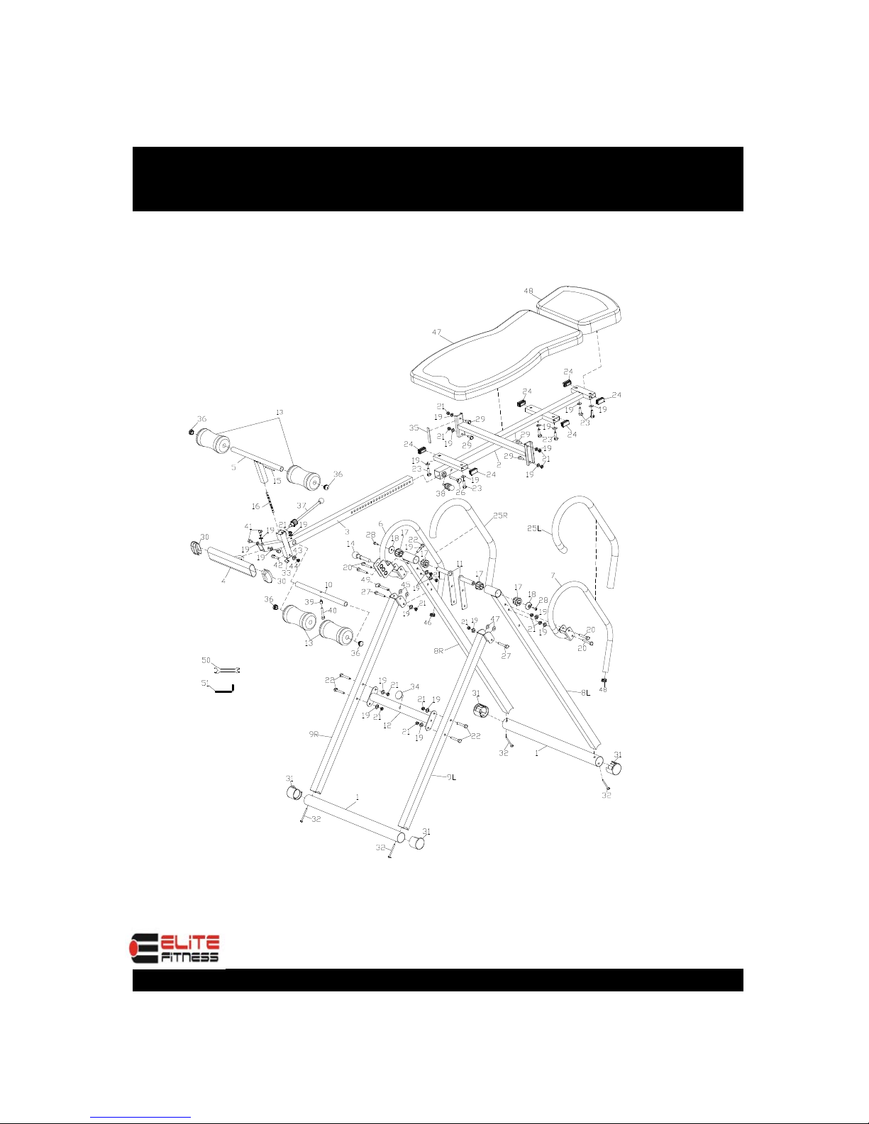
Exploded View
5
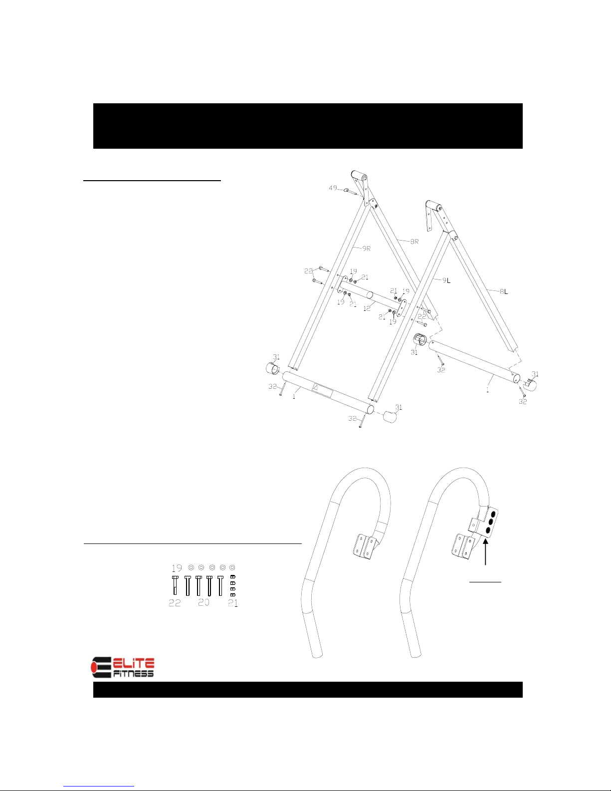
Base Frame and Handlebar Assembly
STEP 1- Base Frame
STEP 1- Base Frame
STEP 1- Base Frame
STEP 1- Base Frame
Unpack base frame from carton.
Attach the front bottom tube(1)
to the front baseframe(9) using
2-bolts(32).
Repeat for the rear bottom tube
as shown.
Attach the cross bar(12) to the
front baseframe(9) using
4-bolts(22),4-flat washers(19)
and 4-nuts(21).
Unfold Base frame- Front ( 9)
from Base frame-Rear (8),
Insert Ball Pin (49) through right
side hole between the 2 frames.
Step 2- Installing Handlebars
Step 2- Installing Handlebars
Step 2- Installing Handlebars
Step 2- Installing Handlebars
Note:
Note:
Note:
Note:
Handlebar
Right (6)
Parts Needed
Rear
Front
! Warning
Left
Right
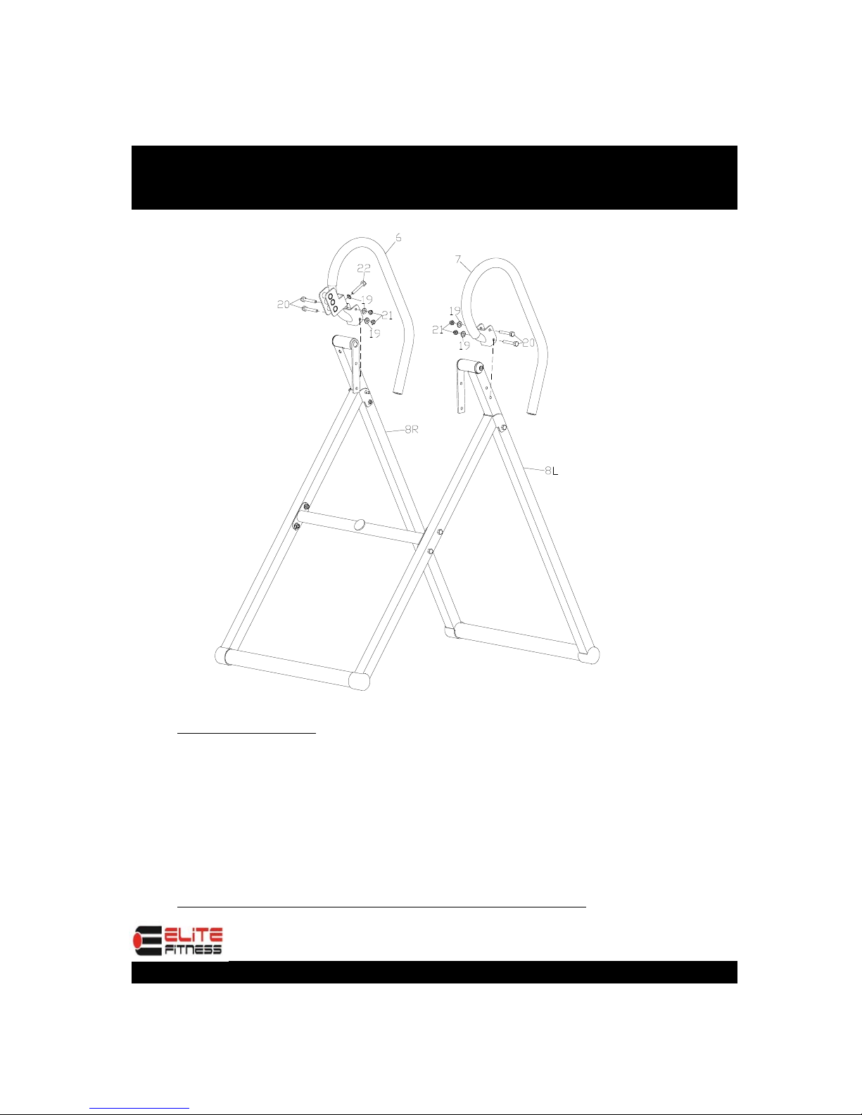
6
Handlebar Assembly
STEP 2 ( Cont)
STEP 2 ( Cont)
STEP 2 ( Cont)
STEP 2 ( Cont)
Attach the Handlebar Right (6) to the Base frame Rear(8R)
using 2 Bolts (20), 2 Washers (19), and 2 Nuts (21). Use
Bolt (22) and Flat Washer (19) to fix the Base frame
Rear(8R) .Repeat for Handlebar Left (7) except there will
not be a part 22 or 19 for this side.
TIGHTEN ALL BOLTS AT THIS TIME
TIGHTEN ALL BOLTS AT THIS TIME
TIGHTEN ALL BOLTS AT THIS TIME
TIGHTEN ALL BOLTS AT THIS TIME
7
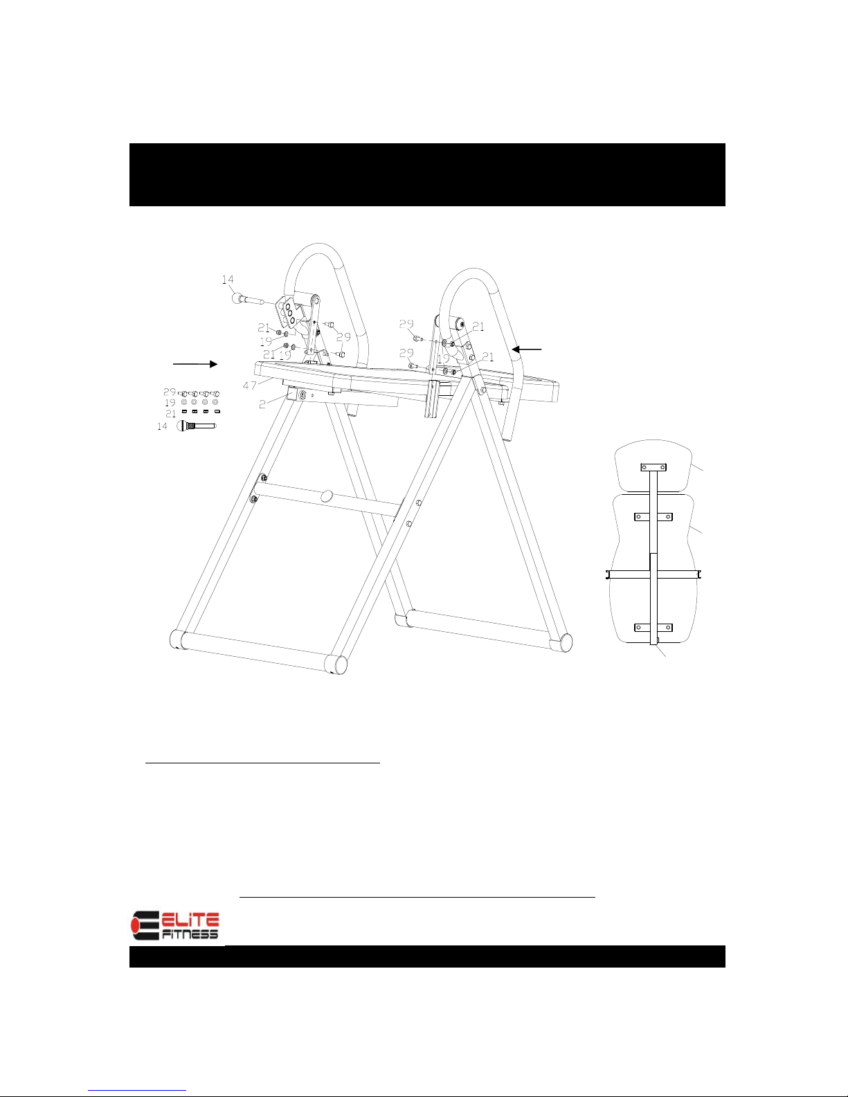
Backrest Assembly to Base Frame
STEP 3 Connecting Backrest
STEP 3 Connecting Backrest
STEP 3 Connecting Backrest
STEP 3 Connecting Backrest
Attach the Completed Backrest Pad and Head Pad Assembly to the
Base frame Unit using Bolts (29), Flat Washers (19) and Lock Nuts (21).
Install Incline Adjustment Bolt (14) into Incline Position 20 Hole and
Tighten.
NOTE: TIGHTEN ALL BOLTS AT THIS TIME
NOTE: TIGHTEN ALL BOLTS AT THIS TIME
NOTE: TIGHTEN ALL BOLTS AT THIS TIME
NOTE: TIGHTEN ALL BOLTS AT THIS TIME
Top of Backrest
Top of Backrest
Top of Backrest
Top of Backrest
pad
pad
pad
padBottom of
Bottom of
Bottom of
Bottom of
Backrest pad
Backrest pad
Backrest pad
Backrest pad
2
47
48
Back
Parts Needed
Back
Front
Left
Right

8
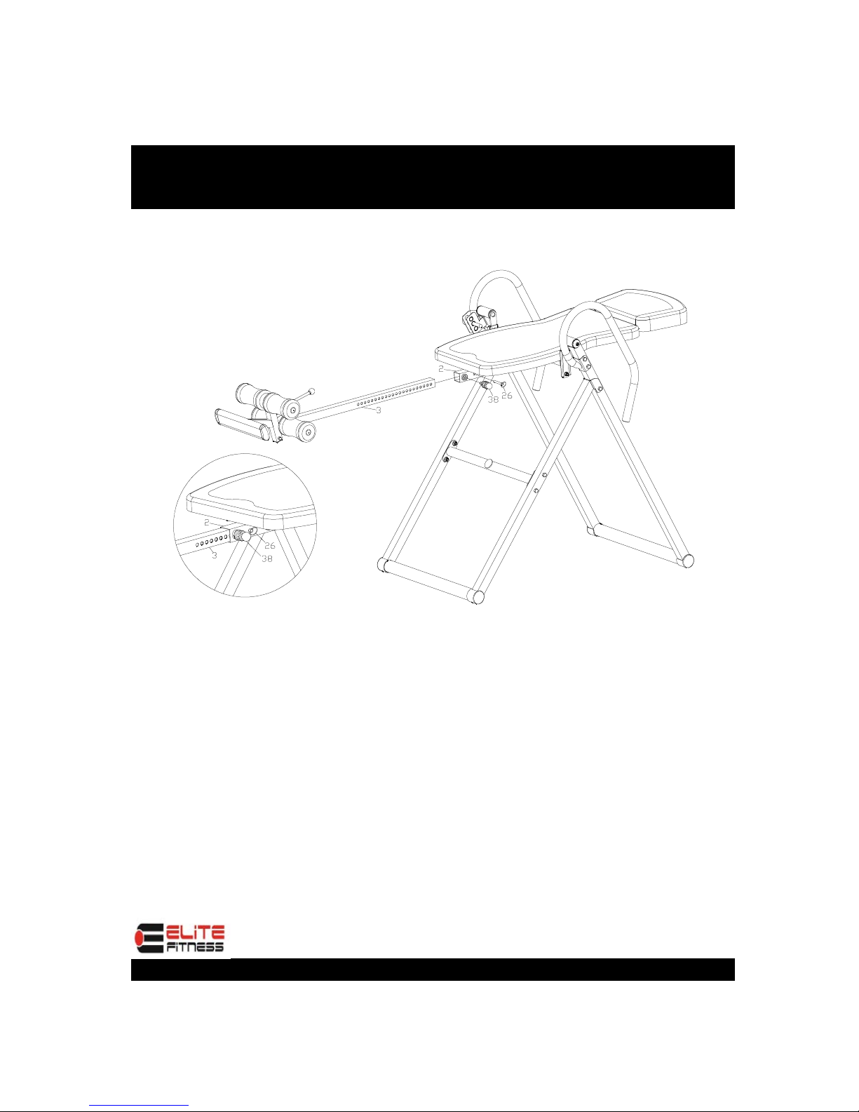
STEP 4-Body Height Adjustment Tube and Rollers
Attach Spring (16) from Adjustable Leg Hold Tube (5) into Body Height
Adjustment Tube (3) using Hexagonal Bolt (44),Washer (43).
Install Leg Tube (10) through hole in Adjustment Tube (3) using Hexagonal
Bolt (40), Metal Bushing (39) Flat Washer (19) and Lock Nut (21)
Insert Leg Tube Adjustment Knob (37) into threaded hole in Adjustment Tube
(3) and tighten.
Slide Foam Leg Rollers (13) over Leg Tube-Rear (10) and over Leg Hold Tube
(5) and secure with Round End Caps (36)
NOTE: TIGHTEN ALL BOLTS AT THIS TIME
Unscrew 3 Bolts(41), 3 washers(19) at the bottom of Body Height Adjustment
Tube (3) .
Install Foot Rest Plate (4) into Body Height Adjustment Tube (3) using 3 Bolts
(41) 3 Washers (19).
9
STEP 5-Final Assembly
Slide Height Adjustment Tube (3) into Backrest
Support Tube ( 2) and lock into place using Height
Adjustment Knob (38).
Note: This product is designed to adjust from 4’10”
to 6’6” with a Maximum User Weight of 300 LBS.
10
Final Assembly
Extreme Products Group
6635 W. Happy Valley Rd.
Suite A-104, #213
Glendale, AZ 85310
Phone: 623-888-6379
Fax: 623-434-9100
www.extremeproductsgroup.com
Make Sure All Nuts
Bolts and Screws
are Completely
Tightened Before
Use.

11
PRECAUTIONS
WARNING: 300 LB WEIGHT CAPACITY
To reduce the risk of serious injury, read all important precautions
instructions and warnings in this manual before using the Inversion
instru
System. Elite Fitness, or Extreme Products Group assumes no
responsibility for personal injury or property damage sustained by or
through the use of the Inversion System.
DO NOT USE THIS INVERSION TABLE WITHOUT A PHYSICIAN’S
APPROVAL, OR IF YOU HAVE ANY OF THE FOLLOWING CONDITIONS
(this list is for reference only, it is not an exhaustive listing):
Pregnancy; Hiatal Hernia, ventral hernia; glaucoma, Retinal Detachment or
Conjunctivitis; High Blood Pressure, Hypertension, recent Stroke or Transient Ischemic
Attack; heart or Circulatory Disorders for which you are being treated; Spinal Injury;
Cerebral Sclerosis; Acutely Swollen Joints; Bone Weakness ( Osteoporosis ), recent
unhealed fractures, medulary pins and surgically implanted orthopedic supports; the
use of anticoagulants, including high doses of aspirin; Middle Ear Infections’ Extreme
Obesity.
IF YOUR PHYSICIAN PERMITS YOU TO USE INVERSION THERAPY,
DO SO UNDER THEIR DIRECTION AND HAVE OUR GUIDELINES
APPROVED BY YOUR PHYSICIAN.
DO NOT LET CHILDREN USE THE INVERSION TABLE
DO NOT
UNSUPERVISED.
THERE ARE CERTAIN PEOPLE WHO SHOULD NEVER INVERT. IF
YOU THINK YOU BELONG TO THIS MINORITY, PLEASE CHECK WITH
YOUR PHYSICIAN BEFORE USING THIS INVERSION TABLE.
INSURE THAT ALL NUTS, BOLTS, AND SCREWS ARE COMPLETELY
TIGHTENED BEFORE USING THIS PRODUCT.
SECURE YOUR ANKLES AND LOCK PULL PIN IN PLACE BEFORE
INVERTING.
12
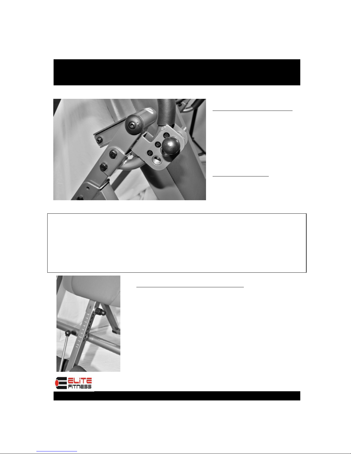
USAGE GUIDELINES
INVERSION SELECTOR PIN
INVERSION SELECTOR PIN
INVERSION SELECTOR PIN
INVERSION SELECTOR PIN
Familiarize yourself with the
Inversion Selector Pin located
on the Right Side of the
Inversion Table. The positioning
of the pin will determine the
degree of Inversion that you are
comfortable with.
The 3 selections are:
20- Slight Inversion
40-Moderate Inversion
60- Enhanced Inversion
NOTE: IT IS STRONGLY RECOMMENDED THAT SOMEONE
BE WITH
YOU DURING INVERSION. ALTHOUGH THE
INVERSION
TABLE IS EASY TO USE, HAVING SOMEONE
NEARBY TO
“SPOT” YOU WILL PROVIDE EXTRA SAFETY
AND
SUPPORT TO THE INVERSION PROCESS.
Body Height and Weight Adjustment:
Body Height and Weight Adjustment:
Body Height and Weight Adjustment:
Body Height and Weight Adjustment:
Before Starting, insure that the
Before Starting, insure that the
Before Starting, insure that the
Before Starting, insure that the
Inversion Table is at the correct
Inversion Table is at the correct
Inversion Table is at the correct
Inversion Table is at the correct
settings to match your height and
settings to match your height and
settings to match your height and
settings to match your height and
weight. As each individual
weight. As each individual
weight. As each individual
weight. As each individual’
’
’
’s body
s body
s body
s body
type is different, you will need to find
type is different, you will need to find
type is different, you will need to find
type is different, you will need to find
the correct settings for your specific
the correct settings for your specific
the correct settings for your specific
the correct settings for your specific
body type
body type
body type
body type

13
USAGE GUIDELINES- Securing Feet and Ankles
WARNING:
WARNING:
WARNING:
WARNING:
ALWAYS WEAR ATHLETIC SHOES WITH LACES TIGHT
TO HELP SECURE YOUR FEET IN THE INVERSION SYSTEM, AND FOR FOOT
PROTECTION WHILE EXERCISING.
ALWAYS MAKE SURE THAT THE ANKLE LOCK IS SECURED SNUGLY
AGAINST YOUR ANKLES AND THAT THE LONG KNOB IS FULLY
TIGHTENED BEFORE YOU USE THE INVERSION SYSTEM
Step 1-
Step 1-
Step 1-
Step 1- Expand the front
rollers by pulling up on the
Leg Tube Adjustment
Knob ( 40)
Step 2-
Step 2-
Step 2-
Step 2- Slide
Feet under
Foam Rollers
Step 3-
Step 3-
Step 3-
Step 3- Contract the front
rollers snugly over feet by
releasing the Leg Tube
Adjustment Knob and making
sure it “Locks” into place

14
USAGE GUIDELINES
Finding the Proper Height and Weight Adjustment
Finding the Proper Height and Weight Adjustment
Finding the Proper Height and Weight Adjustment
Finding the Proper Height and Weight Adjustment
With head flat on back pad, slowly raise one arm up
With head flat on back pad, slowly raise one arm up
With head flat on back pad, slowly raise one arm up
With head flat on back pad, slowly raise one arm up
toward the ceiling. If the bed starts to invert backward,
toward the ceiling. If the bed starts to invert backward,
toward the ceiling. If the bed starts to invert backward,
toward the ceiling. If the bed starts to invert backward,
the height adjustment should be correct.
the height adjustment should be correct.
the height adjustment should be correct.
the height adjustment should be correct.
If the bed does not start to invert, adjust the center slider
If the bed does not start to invert, adjust the center slider
If the bed does not start to invert, adjust the center slider
If the bed does not start to invert, adjust the center slider
arm upward one position at a time, until the bed starts to
arm upward one position at a time, until the bed starts to
arm upward one position at a time, until the bed starts to
arm upward one position at a time, until the bed starts to
invert backward. Remember to use very slow arm
invert backward. Remember to use very slow arm
invert backward. Remember to use very slow arm
invert backward. Remember to use very slow arm
movements.
movements.
movements.
movements.
By raising both hands over your head, the
By raising both hands over your head, the
By raising both hands over your head, the
By raising both hands over your head, the
Inversion Table should now invert to a greater
Inversion Table should now invert to a greater
Inversion Table should now invert to a greater
Inversion Table should now invert to a greater
degree, provided that you are comfortable with
degree, provided that you are comfortable with
degree, provided that you are comfortable with
degree, provided that you are comfortable with
the side adjustment knob being set to 20 or higher.
the side adjustment knob being set to 20 or higher.
the side adjustment knob being set to 20 or higher.
the side adjustment knob being set to 20 or higher.
Note: It is recommended that beginners use the
Note: It is recommended that beginners use the
Note: It is recommended that beginners use the
Note: It is recommended that beginners use the
setting marked 20 for Partial Inversion.
setting marked 20 for Partial Inversion.
setting marked 20 for Partial Inversion.
setting marked 20 for Partial Inversion.
With proper supervision, and provided you are
With proper supervision, and provided you are
With proper supervision, and provided you are
With proper supervision, and provided you are
comfortable with the side adjustment knob
comfortable with the side adjustment knob
comfortable with the side adjustment knob
comfortable with the side adjustment knob
being set to 40 or 60, the Inversion Table will
being set to 40 or 60, the Inversion Table will
being set to 40 or 60, the Inversion Table will
being set to 40 or 60, the Inversion Table will
now allow for a more complete Inversion
now allow for a more complete Inversion
now allow for a more complete Inversion
now allow for a more complete Inversion
position.
position.
position.
position.
CAUTION: BY LOWERING THE HANDS BACK TO THE
CAUTION: BY LOWERING THE HANDS BACK TO THE
CAUTION: BY LOWERING THE HANDS BACK TO THE
CAUTION: BY LOWERING THE HANDS BACK TO THE
STARTING POSITION, THE INVERSION TABLE SHOULD
STARTING POSITION, THE INVERSION TABLE SHOULD
STARTING POSITION, THE INVERSION TABLE SHOULD
STARTING POSITION, THE INVERSION TABLE SHOULD
REVERT BACK TO THE UPRIGHT POSITION. IF IT DOES
REVERT BACK TO THE UPRIGHT POSITION. IF IT DOES
REVERT BACK TO THE UPRIGHT POSITION. IF IT DOES
REVERT BACK TO THE UPRIGHT POSITION. IF IT DOES
NOT, USE THE BUILT IN SIDE HANDLEBARS TO PULL
NOT, USE THE BUILT IN SIDE HANDLEBARS TO PULL
NOT, USE THE BUILT IN SIDE HANDLEBARS TO PULL
NOT, USE THE BUILT IN SIDE HANDLEBARS TO PULL
YOURSELF BACK UP AND RE-ADJUST THE CENTER
YOURSELF BACK UP AND RE-ADJUST THE CENTER
YOURSELF BACK UP AND RE-ADJUST THE CENTER
YOURSELF BACK UP AND RE-ADJUST THE CENTER
SLIDER TO ACCOMMODATE YOUR BODY WEIGHT AND
SLIDER TO ACCOMMODATE YOUR BODY WEIGHT AND
SLIDER TO ACCOMMODATE YOUR BODY WEIGHT AND
SLIDER TO ACCOMMODATE YOUR BODY WEIGHT AND
TYPE.
TYPE.
TYPE.
TYPE.

15
ELITE FITNESS
Distributed By:
Extreme Products Group
6635 W. Happy Valley Rd.
Suite A-104, #213
Glendale, AZ 85310
Phone: 623-888-6379
Fax: 623-434-9100
www.extremeproductsgroup.com
Note: For all parts requests, please visit our web site:
www.extremeproductsgroup.com
Table of contents
Other Elite Fitness Fitness Equipment manuals

Elite Fitness
Elite Fitness IT 9310-E User manual

Elite Fitness
Elite Fitness CHALLENGER User manual

Elite Fitness
Elite Fitness TRACER 8 User manual

Elite Fitness
Elite Fitness R9 DUAL MODE ROWER User manual

Elite Fitness
Elite Fitness IT 9760-E User manual

Elite Fitness
Elite Fitness IT9630-A User manual

Elite Fitness
Elite Fitness Slimline Series User manual

Elite Fitness
Elite Fitness MC 40 User manual

Elite Fitness
Elite Fitness Cobalt User manual

Elite Fitness
Elite Fitness SECA3 User manual


