Eliwell TelevisOut User manual
Parametric controller to capture plant variables in real time and signal alarm conditions when connectd to a supervisor system, both
dedicated (Televis) or standard market ones (MODBUS protocol).
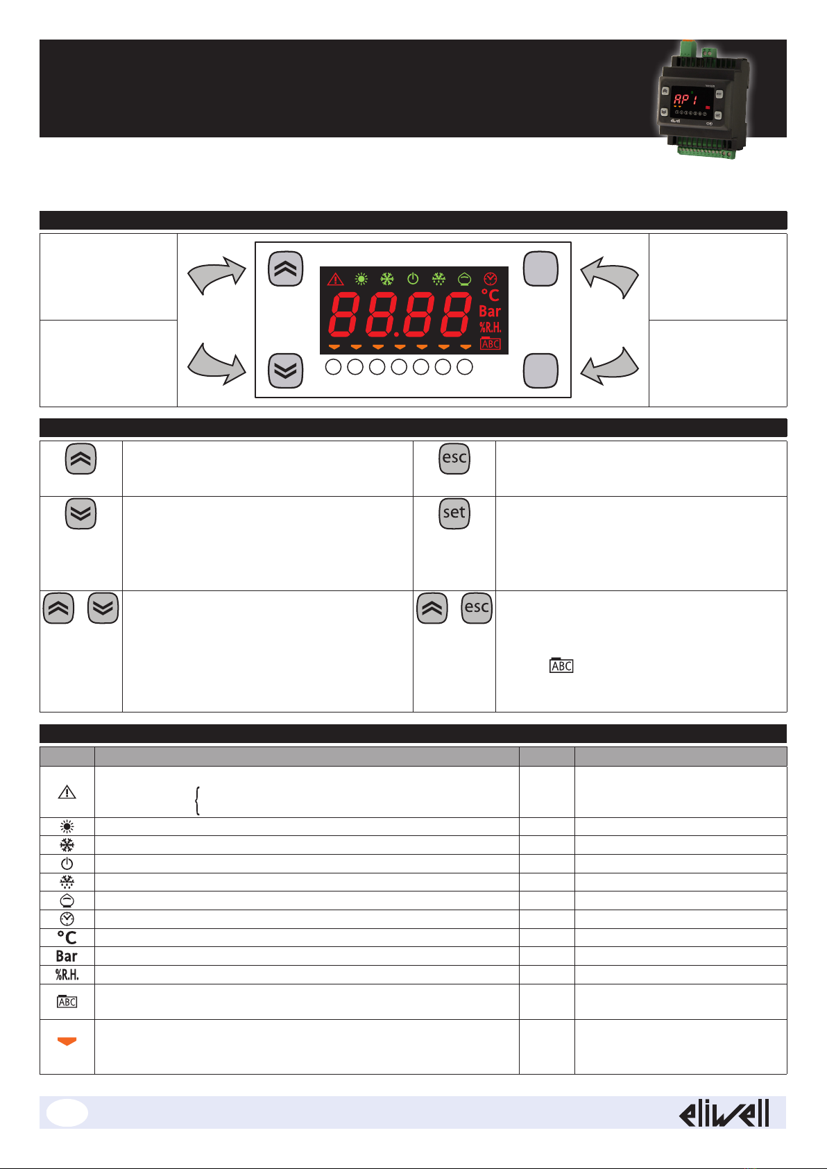
USER INTERFACE
UP
1234 5 6 7
esc
set
ESC
DOWN SET
(ENTER)
KEYS
UP
• Increase values
• Go to next label
ESC
• Exit without saving new settings
• Go back to previous level
DOWN
• Decrease values
• Go to previous label
SET (ENTER)
• Confirm value / exit and save new settings.
• Go to next level (access to folder, sub-folder,
parameter, value)
• Open State Menu
+ON/OFF
Pressing and holding these keys at the same time
for 5seconds or a remote command activates the
ON/OFF function.
In OFF mode, the screen shows the word OFF.
All alarms are disabled, including active and
communication ones.
Probe data capture remains active.
+LOCK
Pressing and holding both keys together for
5seconds or a Supervisor command locks /
unlocks the keypad.
The icon blinks when the keypad is locked;
nothing will happen when a key is pressed, not
even the setpoint will be displayed.
LED
Icon Description Colour Note
Permanently on: alarm active and output set for this alarm
Flashing: alarm silenced and output set for this alarm
alarm active and output not set for this alarm
red silenced from remote and/or DI
Blinks when serial communication is on green
NOT USED green
ON when the device is powered on but not when it is OFF
green
NOT USED green
NOT USED green
NOT USED red
Temperature unit of measurement red
Pressure unit of measurement red
Units of measure for relative humidity red
Permanently on: during navigation
Flashing: keypad locked red
(1) ... (7)
Manages utilities connected to the device.
TelevisIn: indicates if Digital Inputs are active (ON)
TelevisOut: indicates if Digital Outputs are active (ON)
Amber
TelevisIn & TelevisOut
Data acquisition and alarm signalling modules.
EN

MECHANICAL INSTALLATION
The instrument is intended for DIN
rail mounting.
For GUIDA DIN installation, follow
the steps described below:
• Move the two spring docking
devices to their standby position
(use a screwdriver to press against
the relative compartments)
• Then mount the controller on the
DIN RAIL, pressing on the spring
docking devices which will go to
the closing position.
SIDE VIEW
REAR VIEW 3D VIEW
TECHNICAL SPECIFICATIONS (EN 60730-2-9)
Classification: electronic automatic control (not safety) device for incorporation
Mounting: Omega DIN rail.
Type of action: 1.C - 1.Y
Pollution class: 2
PTI of materials used for insulation: PTI 250V (device made with class IIIa material)
Overvoltage category: II
Nominal pulse voltage: 2500V
Temperature: Use: –20 … +55°C • Storage: -40 … +85°C
Power supply: SMPS 100-240 Va ±10% 50/60 Hz
Power consumption: 5W max
Fire resistance category: D
Software class: A
RTC battery life: In absence of external power, the clock battery will last 4 days.
FURTHER INFORMATION
TelevisIn Characteristics
Measurement range: NTC: –50.0...+110°C; PTC: –50.0...+150°C; PT1000: –50.0...+400°C (on display with 3 digits + sign)
Accuracy: NTC, PTC: ±0.5% e.o.s. + 1 digit
PT1000: ±1°C (-30°C ... 30°C) e ±1% e.o.s. (-50°C ... 400°C)
0-1V: ±2% e.o.s.
0-5V, 0-10V, 0...20mA, 4...20mA: ±1% e.o.s.
Impedance: 0-1V: 110kΩ; 0-5V: 110kΩ; 0-10V: 21kΩ; 0...20mA: 100Ω; 4...20mA: 100Ω
Resolution: NTC, PTC, PT1000: 0.1°C; 0-1V, 0-5V, 0-10V, 0...20mA, 4...20mA: 0,1
Analogue Inputs: PB1, PB2, PB5: NTC, PTC, PT1000 inputs or configurable DIs
PB3, PB4:
DI, NTC, 0-1V, 0-5V, 0-10V, 0...20mA or 4...20mA configurable inputs
Digital Inputs: DI1, DI2: Multifunctional digital inputs
Digital Outputs: OUT1: SPST relay 2A max 250Va
TelevisOut Characteristics
Digital Outputs: OUT1, OUT2, OUT3: SPST relay 2A max 250Va
OUT4: SPDT relay 2A max 250Va
OC outputs/Digital Inputs: OUT5/DI1: OC Analogue Output or voltage-free Digital Input
OUT6/DI2: OC Analogue Output or voltage-free Digital Input
The two analogue outputs are low voltage (SELV) Open Collector (OC) ones: PWM with
- Precision: 2%;
- Nominal range: 0…16.9Vc(12V~ rectified); closure 12Vc;
- Maximum current: 35mA (min load of 340Ohm @12Vc)
NOTA: ** Outputs OUT5 and OUT6 (typically connected to the device's auxiliary 12Vcoutput) cannot
deliver more than 70mA in total. Any other loads connected to the same 12Vc auxiliary output
must also be taken into account.
Mechanical Characteristics
Container: PC+ABS resin casing, UL94 V-0
Dimensions: 4 DIN-rail
Terminals: removable screw terminals with 2.5mm2cross-section.
Connectors: TTL for MFK / Device Manager connection (via DMI)
RS485 to connect to TelevisSystem/Modbus supervisor.
Humidity: Usage / Storage: 10...90% RH (non-condensing)
Regulations
Electromagnetic compatibility: The device complies with Directive 2004/108/EC
Safety: The device complies with Directive 2006/95/EC
Food Safety: The device complies with standard EN13485 as follows:
- suitable for storage
- application: air
- climate range: A
- measurement class 1 in the range from -25°C to 15°C (*)
(*with Eliwell probes only)
NOTE: The technical specifications stated in this document regarding the measurement (range, accuracy, resolution, etc.)
referstrictly to the instrument and not to any accessories provided, such as the probes.
This means, for example, that the error introduced by the probe must be added to the error of the instrument.
SUPERVISION
The connection to supervisor systems is via the RS-485 port and can use Televis or Modbus protocols.
The protocol to be used must be configured to ensure the proper function of TelevisIn and/or TelevisOut. The parameters to be set
are in the “Add” folder, under the “Installer” parameters (see section entitled “Password”), as listed below.
N.B.: 1) All communication parameters in the “Add” folder are not in the vectors.
2) A double terminal clip is provided as an RS485 connection accessory RS485
to connect two RS-485 in parallel.
COMMUNICATION PARAMETERS (Add)
PAR. Description UM Range Value
PtS Select protocol (t = Televis; d = ModBus). flag t/d t
dEA Device address: indicates the device address to the management protocol. num 0 ... 14 0
FAA Family address: indicates the device family to the management protocol. num 0 ... 14 0
Adr Modbus protocol controller address num 1 ... 250 1
Pty Sets Modbus parity bit (n = none; E = even; o = uneven). num n/E/o n
StP Sets Modbus stop bit: (1b = 1 BIT; 2b = 2 BIT). flag 1b/2b 1b
LOADING DEFAULT APPLICATIONS
The procedure for loading one of the default applications is:
• At power-on of the device, keep the key pressed: the label “AP1” will appear.
• Scroll through the various applications (“AP1”... “AP8”) using the and keys.
• Select the application you want using the key (“AP3” in the example) or cancel the operation
by pressing the key or by timeout.
• If the operation is successful, the display will show “y”, if not it will show “n”.
• After a few seconds the instrument will return to the main display.
RESET PROCEDURE
TelevisIn & TelevisOut can be RESET and the default factory settings restored in a simple and user-friendly way.
This is done by simply reloading one of the basic applications (see “Loading default applications”).
You may need to RESET the instrument in circumstances in which the normal operation of the instrument is compromised or if you
decide to restore the instrument to its default configuration (e.g. Application “AP1” values).
IMPORTANT! This operation resets the instrument to its initial state, returning all the parameters to their default values.
This means that all changes made to operating parameters will be lost.
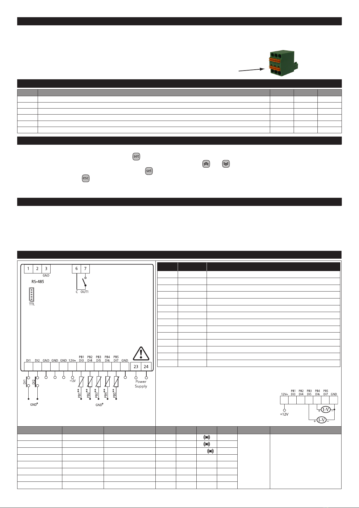
TelevisIn (Connections and Default applications)
TelevisIn
100-240Va
+
–
}
}
}
No. Label Description
1-2-3 RS-485 Serial RS-485 (1 = “-”; 2 = “+” and 3 = “GND”)
6 C Common
7 OUT1 NO relay output OUT1 - high voltage (2A - 230Va)
DI1 Digital Input 1
DI2 Digital Input 2
GND Ground
12VcAuxiliary power supply 12Vc
PB1/DI3 Analogue input 1 configurable as: DI, NTC, PTC and PT1000
PB2/DI4 Analogue input 2 configurable as: DI, NTC, PTC and PT1000
PB3/DI5 Analogue input 3 configurable as: DI, NTC, V*** and I***
PB4/DI6 Analogue input 4 configurable as: DI, NTC, V*** and I***
PB5/DI7 Analogue input 5 configurable as: DI, NTC, PTC and PT1000
GND Ground
23-24 Power supply Power supply 100-240Va
NOTES
* Connect the terminal to one of the GND terminals.
** Analogue Inputs PB1...PB5 can also be configured
as DIs (H4x="DI")
*** The V and I configurable inputs (PB3 e PB4) are:
• V = 0-1V; 0-5V and 0-10V
• I = 0...20mA and 4...20mA
Function Label Parameters AP1 AP2 AP3 AP4 AP5...AP8 Note
Input DI1 H11
Applications can
be configured
by users
• Use sensor SEMITEC 103 AT with
NTC analogue inputs (10KOhm /
25°C).
• Digital inputs DI1/DI2 are low volt-
age digital inputs and the closing
current for ground is0.5mA.
Input DI2 H12
Input Pb1 / DI3 H41, H13** PTC DI - NTC
Input Pb2 / DI4 H42, H14** PTC
Input Pb3 / DI5 H43, H15** 4...20mA 4...20mA
Input Pb4 / DI6 H44, H16** 4...20mA
Input Pb5 / DI7 H45, H17** PTC
Output OUT1 H21

TelevisOut (Connections and Default applications)
TelevisOut
100-240Va
+
–
}
}
8910 11 12 No. Label Description
1-2-3 RS-485 Serial RS-485 (1 = "-"; 2 = "+" and 3 = "GND")
6 C Common
7 OUT1 NO relay output OUT1 - high voltage (2A - 230Va)
8 OUT2 NO relay output OUT2 - high voltage (2A - 230Va)
9 OUT3 NO relay output OUT2 - high voltage (2A - 230Va)
10 OUT4 NC relay output OUT4 - high voltage (2A - 230Va)
11 OUT4 Common relay output OUT4 - high voltage (2A - 230Va)
12 OUT4 NO relay output OUT4 - high voltage (2A - 230Va)
OUT5/DI1 Low voltage digital input 1, also configurable as Analogue Output
OUT5 - low voltage (SELV) OC: PWM
OUT6/DI2 Low voltage digital input 2, also configurable as Analogue Output
OUT6 - low voltage (SELV) OC: PWM
GND Ground
12VcAuxiliary power supply 12Vc
23-24 Power supply Power supply 100-240Va
NOTES
* Connect the terminal to one of the GND terminals.
** SELV: SAFETY EXTRA LOW VOLTAGE
Function Label Parameters AP1 AP2...AP8 Note
Input/Output
DI1 / OUT5
H11
Applications
can be configured
by users
• Digital inputs DI1/DI2 are low voltage digital inputs
and the closing current for ground is 0.5mA.
Input/Output
DI2 / OUT6
H12
Output
OUT1
H21
NO-LINK
Output
OUT2
H22
Output
OUT3
H23
Output
OUT4
H24
PASSWORDS
Password PA1: allows access to the “User” parameters. By default the password is disabled (PS1=0).
Password PA2: allows access to “Installer” parameters. By default the password is enabled (PS2=0).
(For more details, see the User Manual which can be downloaded from the Eliwell website).
The visibility of “PA2” is:
1) PA1 and PA2≠0: Press and hold for longer than 5seconds to display PA1 and PA2. You can then decide whether to access
the “User” parameters (PA1) or the “Installer” parameters (PA2).
2) Otherwise: Password PA2 is at the end of the level1 parameters. If enabled, it will be required when accessing the “Installer”
parameters.
NOTE: If the value entered is incorrect, label PA1/PA2 will be shown again and the procedure must be repeated.
MACHINE STATE MENU
Press the once to open this menu.
Use the and keys to browse the menu. Press to access the parameters or values it contains.
The visibility of folders depends on the configuration:
• AL: alarms (always present, if there are no active alarms, the display readsd “----”)
• Pb: Pbx values (for configured inputs only) and dEP (dewpoint)
• di: DI state (configured inputs only)
• do: DO state (configured outputs only)
Pb, di and do are only visible if there is at least one configured input/output.
PROGRAMMING MENU
To access the “Programming” menu hold down the key for more than 5 seconds. If enabled, the instrument will request an
access PASSWORD, either PA1 for “User” parameters or PA2 for “Installer” parameters (see “PASSWORD” section).
“User” parameters:
When accessed the display will show the first parameter (e.g. “diF”). Press and to scroll through all
parameters in the current level. Select the desired parameter by pressing . Press and to change it
and to save changes.
“Installer” parameters:
When accessed the display will show the first folder (e.g. “diF”).
(For the list of “Installer” parameters, see the User Manual which can be downloaded from the Eliwell website).
NOTE:
It is strongly recommended that you switch the device off and on again each time parameter configuration is changed,
inorder to prevent the configuration and/or ongoing timings from malfunctioning.

code 9IS54225-1 - TelevisIn&Out - rel.05/12 - EN -
© Eliwell Controls s.r.l. 2012 - All rights reserved.
Eliwell Controls s.r.l.
Via dell’Industria, 15 • Z.I. Paludi
32010 Pieve d’Alpago (BL) - ITALY
Telephone: +39 0437 986 111
Fax: +39 0437 989 066
www.eliwell.com
Technical Customer Support:
Technical helpline: +39 0437 986 300
E-mail: [email protected]
Sales:
Telephone: +39 0437 986 100 (Italy)
+39 0437 986 200 (other countries)
E-mail: [email protected]
COPY CARD / UNICARD
When connected to the serial port (TTL), the Copy Card/Unicard allows instrument parameters to be programmed rapidly.
EnterPA2 to access “Installer” parameters, scroll through the folders using and until folder FPr is displayed.
Press to select it, scroll through the parameters using and then press (e.g. UL) to select the function.
• Upload (UL):
select UL and press . This function uploads the programming parameters from the instrument to the card.
If the operation is successful, the display will show “y”, otherwise it will show “n”.
• Format (Fr): This command is used to format the copy card (which is necessary when using the card for the first time).
Important: the Fr parameter deletes all data present. This operation cannot be reversed.
• Download (dL):
Connect the Copy Card when the instrument is switched off. At power-on, data will automatically start
downloading from the USB key to the instrument. At the end of the lamp test, the display will show “dLy”
ifthe operation was successful and “dLn” if not.
NOTE: After the download, the instrument will use the newly uploaded map settings.
ELECTRICAL CONNECTIONS
Important! Make sure the machine is switched off before working on the electrical connections.
The instrument is equipped with screw connectors to connect power cables with a maximum cross-section of 2.5mm2 (one wire per
terminal). Make sure that the power supply is of the correct voltage for the device.
Temperature probes (NTC, PTC, PT1000) have no connection polarity and can be extended using a normal bipolar cable (note that
the extension of the probes influences the instrument's EMC electromagnetic compatibility: take great care with the wiring).
Ratiometric or pressure probes (4...20mA), have a connection polarity.
Probe cables, power supply cables and the RS485 serial cable should be routed separately from power cables.
DISCLAIMER
This document is the exclusive property of ELIWELL CONTROLS SRL and may not be reproduced or circulated without the express
permission of ELIWELL CONTROLS. While all possible care has been taken to ensure the accuracy of this document, ELIWELL
CONTROLS SRL cannot accept liability for any damage resulting from its use. The same applies to any person or company involved
in preparing and editing this document. ELIWELL CONTROLS SRL reserves the right to make aesthetic or functional changes at any
time without notice.
LIABILITY AND RESIDUAL RISKS
ELIWELL CONTROLS SRL declines all liability for damage due to:
- installation/use other than expressly specified and, in particular, in conflict with the safety prescriptions set down in regulations
and/or specified in this document;
- use on panels that do not provide adequate protection against electric shocks, water or dust in the adopted mounting conditions;
- use on panels allowing access to dangerous parts without having to use tools;
- tampering with and/or modification of the product;
- installation/use on panels that do not comply with statutory laws and regulations.
CONDITIONS OF USE
Permitted use
For safety reasons, the device must be installed and used according to the instructions provided. In particular, parts carrying dan-
gerous voltages must not be accessible in normal conditions. The device must be adequately protected from water and dust with
regard to the application, and must only be accessible using tools (with the exception of the front panel). The device is suitable for
use in household refrigeration appliances and/or similar equipment and has been tested for safety aspects in accordance with the
harmonized European reference standards.
Improper use
Any use other than that expressly permitted is prohibited. The relays provided are of a functional type and can be subject to failure:
any protection devices required by product standards, or suggested by common sense for obvious safety requirements, must be
installed externally to the controller.
This manual suits for next models
1
Table of contents
Other Eliwell Measuring Instrument manuals


 user manual")


