Eliwell RadioAdapter User manual
RadioAdapter
MANAGEMENT AND MONITORING
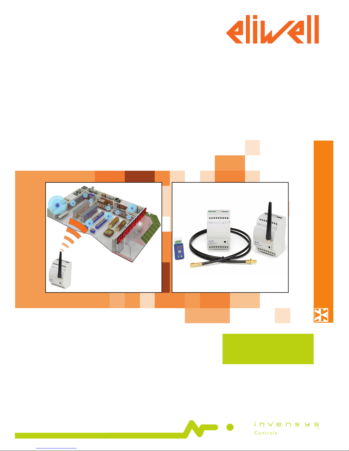
ISM 2.4 GHz wireless system for plant monitoring
and control
USER
MANUAL

RadioAdapter
SUMMARY
1 -INTRODUCTION ..................................................................................................... 3
1.1 - REGULATIONS .......................................................................................................................................3
1.2 - TECHNICAL DATA (EN 60730-2-9) .......................................................................................................3
1.3 - CIRCUIT DIAGRAM ...............................................................................................................................4
1.4 - MECHANICAL ASSEMBLY .....................................................................................................................4
1.5 - INSTALLING THE ANTENNA (NO FCC MODELS) .................................................................................4
1.6 - MODELS AND ACCESSORIES ...............................................................................................................5
1.7 - DEFINITIONS .........................................................................................................................................5
2 - INSTALLATION. ...................................................................................................... 6
2.1 - HOW TO INSTALL THE PAN-C ...............................................................................................................6
2.1.1 - INITIALIZING THE PAN-C ...........................................................................................................................................................................6
2.1.2 - CHANNEL SEARCH .................................................................................................................................................................................... 6
2.1.3 - SAVING PAN-C SETTINGS ......................................................................................................................................................................... 6
2.2 - HOW TO INSTALL A NODE ...................................................................................................................7
2.2.1 - INITIALIZING A NODE ............................................................................................................................................................................... 7
2.2.2 - ADDRESS CONFIGURATION AND SEARCHING FOR CONNECTED DEVICES ........................................................................................ 7
2.2.3 - SAVING SETTINGS ..................................................................................................................................................................................... 7
2.3 - HOW TO INSTALL A REPEATER ............................................................................................................8
2.3.1 - INITIALIZING A REPEATER ........................................................................................................................................................................8
2.3.2 - SELF-CONFIGURING A REPEATER ............................................................................................................................................................8
2.3.3 - SAVING REPEATER SETTINGS ...................................................................................................................................................................8
2.4 - CONFIGURING THE PAN-C ...................................................................................................................9
2.4.1 - TRANSFERRING NETWORK CONFIGURATION TO THE PAN-C ............................................................................................................... 9
2.5 - CHANGES TO NETWORK .....................................................................................................................9
2.5.1 - ADDING A NEW NODE .............................................................................................................................................................................. 9
2.5.1 - ADDING A NEW DEVICE ........................................................................................................................................................................... 9
3 - TROUBLESHOOTING .......................................................................................... 10
3.1 - REPLACING THE PAN-C ..................................................................................................................... 10
3.2 - REPLACING A NODE .......................................................................................................................... 10
3.3 - REPLACING A DEVICE........................................................................................................................ 10
3.4 - RESETTING A NODE........................................................................................................................... 10
3.5 - CHANGING CHANNEL ....................................................................................................................... 11
3.5.1 - SCANNING TO FIND A NEW CHANNEL ..................................................................................................................................................11
3.5.2 - SETTING COMMUNICATION CHANNEL MANUALLY .............................................................................................................................11
4 - WARNINGS .......................................................................................................... 12
4.1 - ELECTRICAL CONNECTIONS ............................................................................................................. 12
4.2 - DISCLAIMER ....................................................................................................................................... 12
4.3 - RESPONSIBILITY AND RESIDUAL RISKS ........................................................................................... 12
4.4 - CONDITIONS OF USE ........................................................................................................................ 12
RadioAdapterPag. 3/12
RadioAdapter provides a cost-effective, reliable way of building cable-free communication networks between monitoring systems
and controllers or of extending existing networks.
RadioAdapter features IEEE 802.15.4 standard functions and runs on ISM frequency band at 2.4GHz.
Thanks to MESH networking technology and associated dynamic routing combined with RadioAdapter capabilities to act as a
repeater for adjacent nodes, large surface areas can be covered, getting around blocked paths to send or receive messages and
continuous function guaranteed even when one or more nodes breaks down.
1.1 - REGULATIONS
Radio and telecommunications equipment: Directive 95/05/EC.
The use is permitted in the countries belonging to the European Economic Area (EEA) and where the FCC is recognized (see box).
FCC notes (only for model with internal antenna)
• This device complies with Part 15 of the FCC Rules. Operation is subject to the following two conditions: (1) this
device may not cause harmful interference, and (2) this device must accept any interference received, including
interference that may cause undesired operation.
• Unauthorized repairs, changes or modifications could result in permanent damage to the equipment and void
your warranty and your authority to operate this device under Part 15 of the FCC Rules.
• NOTE: This equipment has been tested and found to comply with the limits for a Class A digital device, pursuant
to part 15 of the FCC Rules. These limits are designed to provide reasonable protection against harmful
interference when the equipment is operated in a commercial environment. This equipment generates, uses, and
can radiate radio frequency energy and, if not installed and used in accordance with the instruction manual, may
cause harmful interference to radio communications.
Operation of this equipment in a residential area is likely to cause harmful interference in which case the user will
be required to correct the interference at his own expense.
IC note (only for model with internal antenna)
• This device is compliant to RSS 102
• Cet instrument répond aux normes RSS 102
1.2 - TECHNICAL DATA (EN 60730-2-9)
Class of use Class 4 classification ISA SP100.11 (do not use for safety devices)
Network architectures permitted star, tree and MESH
Protocols supported Televis e Modbus RTU
Modbus configurations permitted:
serial speed: 9.600 / 19.200 bps
parity: Even / Odd / None
stop bit: 1
Frequency band ISM 2.400 GHz...2.485 GHz (<10mW EIRP)
Channel selection Automatic
Max. radio packet payload size 52 bytes
Antenna 2.4 GHz integrated, multidirectional or external
(only on RadioAdapter EXT models - see 1.4 Models and Accessories)
Maximum number of nodes per network 100
Maximum number of controllers per NODE 240
Maximum response time of radio 800msec (value to be added to the response time of the controller to calculate
transmission timeout)
Container container: 3 plastic DIN modules
Mounting on DIN guides
Operating temperature -5...60°C
Storage temperature -20...85°C
Operating and storage environment humidity 10...90% (non-condensing)
Serial connections TTL port for connection to devices
RS-485 serial port (on two RadioAdapter /S models only)
Insulation class 2
Consumption 2W
Power supply 100...240 Va ±10% 50/60Hz
1 -INTRODUCTION
RadioAdapter Pag. 4/12
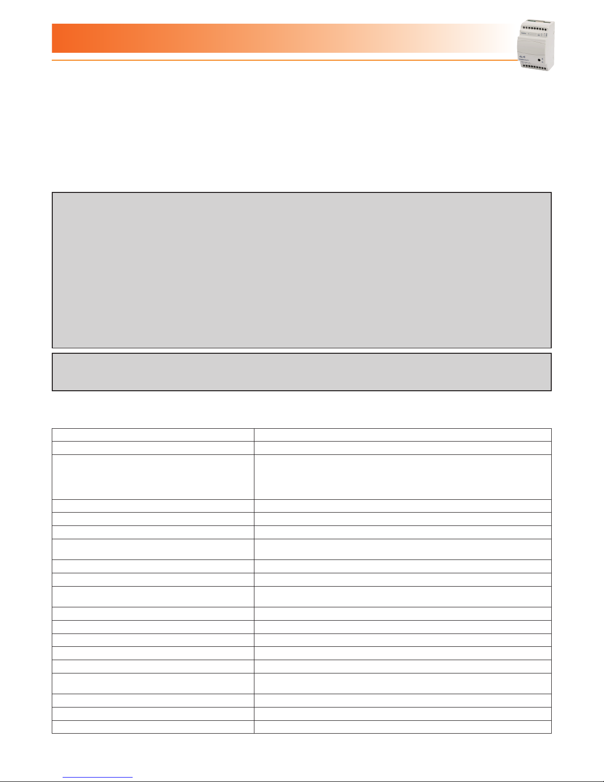
1.3 - CIRCUIT DIAGRAM
Power Supply
TTL
10 11
TTLTTLTTL
RadioKey
RadioAdapter
RS-485
TTL
RadioKey
Power
Supply
A
B
C
}
NOT for
FCC models
TERMINALS
RadioKey Connector to connect the RadioKey
TTL TTL serial port to connect directly to devices
7-8-9 RS-485 serial port to connect directly to devices or to the
monitoring system
(on in RadioAdapter /S models)
10-11 Power supply 100...240Va
A SMA connector for external antenna
(only on RadioAdapter EXT models)
B Cable for external antenna (length: 1m)
C External antenna
IMPORTANT: For RadioAdapters with an external antenna, use Eliwell
supplied cable and antenna only.
IMPORTANT! Do not touch the SMA connection
for external antenna (A) as static
electricity may have built up!
1.4 - MECHANICAL ASSEMBLY
This device is designed to be wall-mounted or on a DIN rail.
The ambient temperature range for correct operation is -5 to 60°C, and the permitted humidity range is 10 to 90% (non-condensing).
Sufficient ventilation should be provided if the device is installed inside an electrical panel or switchboard.
Do not install the device in damp or dirt-laden areas.
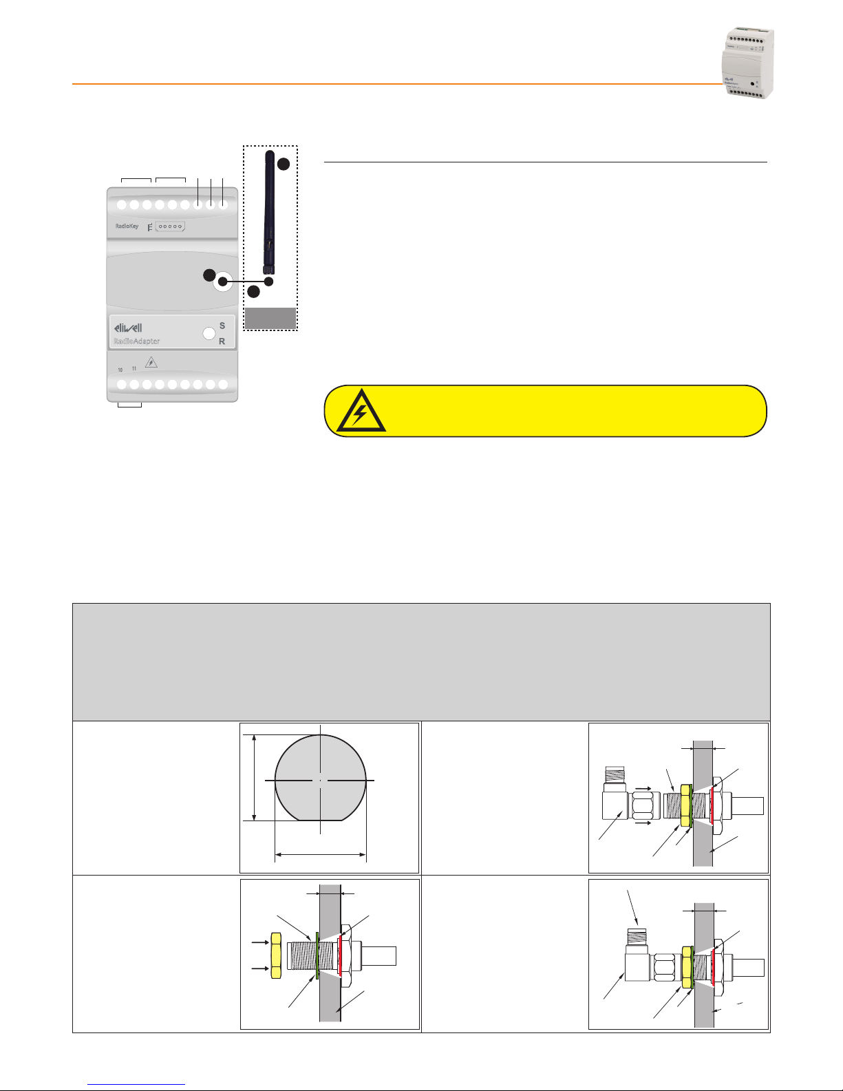
1.5 - INSTALLING THE ANTENNA (NO FCC MODELS)
The antenna can be inserted straight into the RadioAdapter connector or panel-mounted and connected to RadioAdapter using
the cable supplied in the Antenna kit.
N.B.: The panel that the antenna is mounted on must be no more than 3mm thick.
For the panel mounting of the antenna, please follow the proceduredescribe below:
ANTENNA KIT COMPONENTS:
- 1m cable
- antenna + SMA 90° connector
- Seal ring, nut and washer to fit the cable to SMA 90° connector
- Drill a hole in the panel as
shown in Figure 1:
6.8 mm
7.2 mm
- Tighten the nut to firmly clamp
the cable (see Figure 3)
- Rub some more thread locker
onto the connector as shown
in Figure 3
max 3 mm
Washer
Threadlocker O-ring
Panel
Nut
Connettor
SMA 90°
- Fit the seal ring (o-ring) to the
end of the cable to be fitted to
the panel (see Figure 2)
- Insert the end of the cable to be
fitted to the panel through the
previously drilled hole.
- Slip the washer over the end of
cable pushed through the hole
(see Figure 2).
- Rub a little thread locker onto
the connector as shown in
Figure 2.
max 3 mm
Washer
Threadlocker O-ring
Panel
Nut
- Tighten the SMA 90° connector
and fit it to the antenna (see
Figure 4)
NOTE: LOCTITE® 243
threadlocker is
recommended.
max 3 mm
Washer
O-ring
Panel
Nut
Connector
SMA 90°
Fit the antenna
Figura 3
Figura 2
Figura 1
Figura 4
RadioAdapterPag. 5/12
1.6 - MODELS AND ACCESSORIES
Model Name Description
RadioAdapter (FCC) Radio device with internal antenna and TTL connection
RadioAdapter /S (FCC) Radio device with internal antenna and TTL + RS-485 connections
RadioAdapter EXT Radio device with external antenna and TTL connection
RadioAdapter /S EXT Radio device with external antenna and TTL and RS-485 connections
Accessory Description
Kit Antenna esterna + cavo Antenna + SMA 90° connector + 1m cable
RadioKey Network configuration device (1 RadioKey per network)
Radiokey Part Number Tipo Radiokey Descrizione
CCA0B0T01T000 RadioKey Televis
CCA0B0T01M000 RadioKey Modbus bit rate: 9600 bps; parity: even; stop bit: 1
CCA0B0T01M100 RadioKey Modbus bit rate: 9600 bps; parity: odd; stop bit: 1
CCA0B0T01M200 RadioKey Modbus bit rate: 9600 bps; parity: none; stop bit: 1
CCA0B0T01M300 RadioKey Modbus bit rate: 19200 bps; parity: even; stop bit: 1
CCA0B0T01M400 RadioKey Modbus bit rate: 19200 bps; parity: odd; stop bit: 1
CCA0B0T01M500 RadioKey Modbus bit rate: 19200 bps; parity: none; stop bit: 1
NOTE: The features described in this table depend on the value of the 11th digit of the RadioKey Part Number
1.7 - DEFINITIONS
PAN-C
PAN-C
NODE
1
Repeater
NODE
2
NODE
3
RS-485
TTL/RS-485
RS-485 120 Ω
RS-485
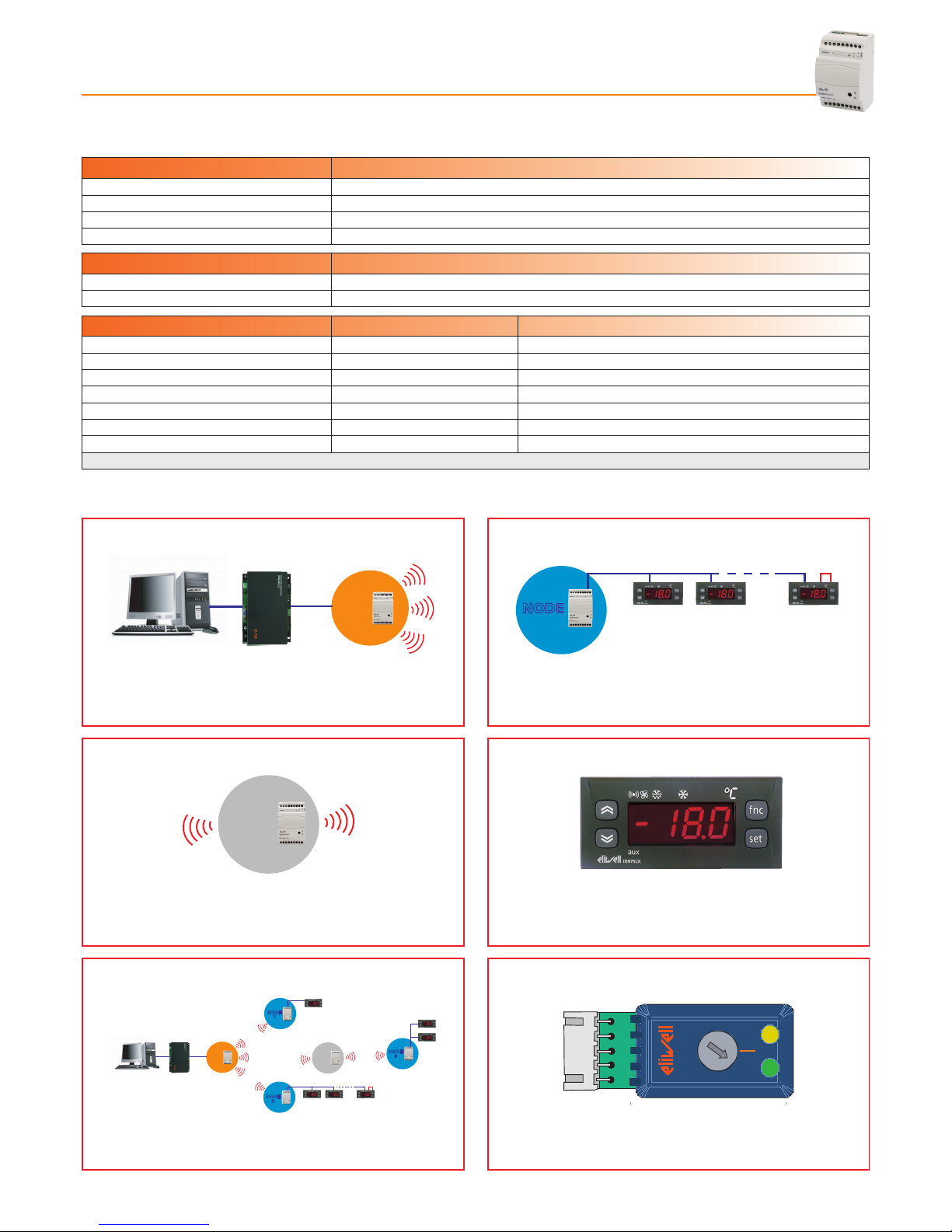
PAN-C (PAN-Coordinator) is the network coordinator.
PAN-C is the access point that the monitoring system is
connected to
NODE
NODE
120 Ω
RS-485
A NODE is a RadioAdapter connected to one or more
devices.
REPEATER
PAN-C
NODE
1
Repeater
NODE
2
NODE
3
RS-485
TTL/RS-485
RS-485 120 Ω
RS-485
The repeater is a RadioAdapter that is not connected to any
devices. It is installed between two NODES when the signal
between the two has to travel too far and is too weak as a result.
INSTRUMENT
Controller fitted with serial port that can be connected to
the NODE via a Televis or Modbus protocol.
NETWORK
PAN-C
NODE
1
Repeater
NODE
2
NODE
3
RS-485
TTL/RS-485
RS-485 120 Ω
RS-485
A network featuring at least one PAN-C and one or more
NODES and repeaters
RADIOKEY
RadioKey
NP
9
8
7
6
5
4
3
2
1
0
Device used for network installation and configuration.
RadioAdapter Pag. 6/12
The RadioAdapter device can function as part of the network, as a PAN-C, as a NODE or a repeater.
The RadioAdapter should therefore be configured accordingly when it is actually inserted into the network.
The communication network consists of:
- A RadioAdapter configured as PAN-C and connected to a monitoring system (Televis or Modbus)
- A RadioKey device to identify and configure the network.
- Up to 100 RadioAdapters serving as communication NODES for devices. Just one device or a sub-network of
up to 240 devices can be connected to a node.
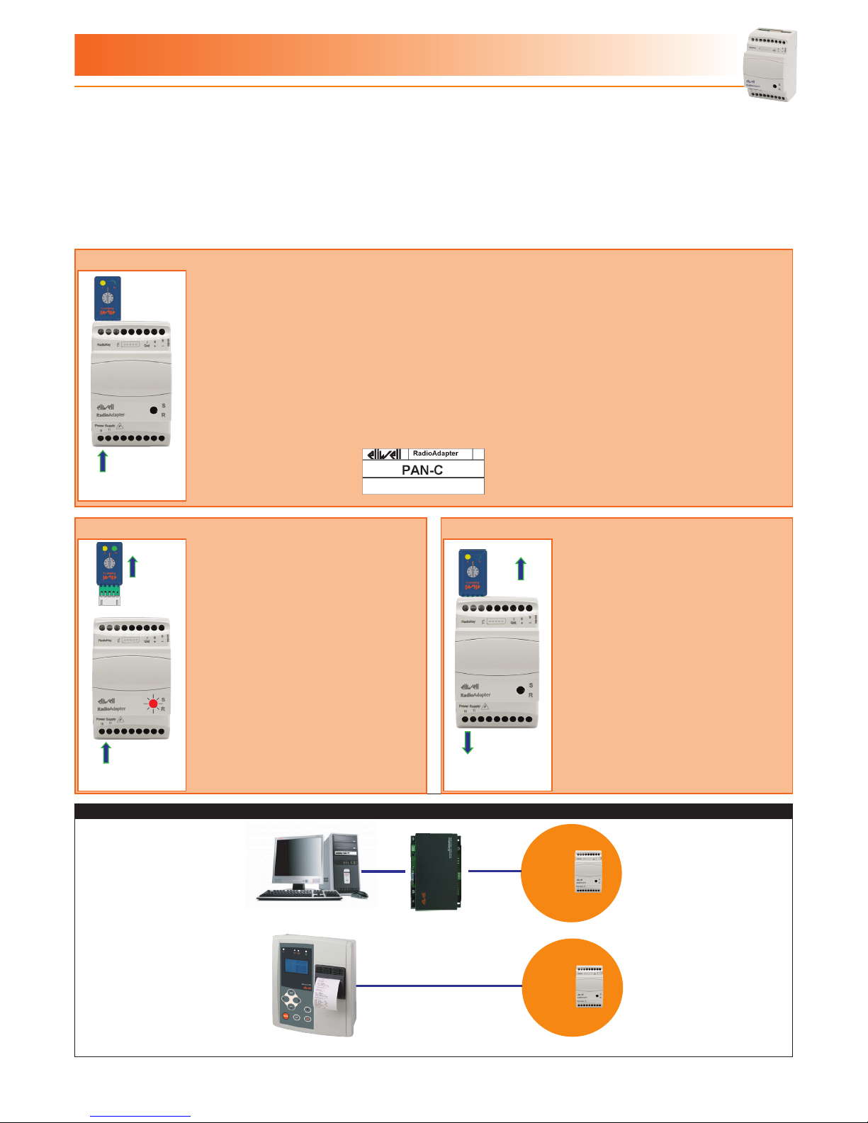
2.1 - HOW TO INSTALL THE PAN-C
2.1.1 - INITIALIZING THE PAN-C
Power
Supply
Power
Supply
Power
Supply
- Connect the RadioAdapter to the power supply.
- Set the switch on the RadioKey to position 0.
- Connect the RadioAdapter to the RadioKey and wait for the YELLOW LED (P) (on the RadioKey)
to switch on (GREEN LED (N) off).
At this point, theRadioAdapter is now configured as PAN-C and all PAN-C information is sent to the
RadioKey.
- From now on, the RadioKey can only be used with this network.
- We recommend you mark this RadioAdapter with the sticker supplied.
2.1.2 - CHANNEL SEARCH 2.1.3 - SAVING PAN-C SETTINGS
Power
Supply
Power
Supply
Power
Supply
- Install the PAN-C and connect it to
the power supply when all potential
forms of radio interference are present
(e.g. alarm systems, WiFi, etc..)
- The PAN-C will start searching for a
free channel: this step is indicated by
the flashing RED LED (it will take about
4 minutes)
- When this scan has finished, the RED
LED will start to blink more slowly
Power
Supply
Power
Supply
Power
Supply
- Set the switch on the RadioKey to
position 0 and connect it to the PAN-C
in turn connected to the power supply.
- When the YELLOW LED (P) on
the RadioKey lights up, disconnect the
RadioAdapter from the power supply.
- Disconnect the RadioKey.
- Install and configure NODES and any
REPEATERS.
(see section “How to install a NODE”)
NETWORK STRUCTURE
PAN-C
RS-485
PAN-C
RS-485
IMPORTANT! RadioAdapter is not compatible with PC Interface USB
2 - INSTALLATION
RadioAdapterPag. 7/12
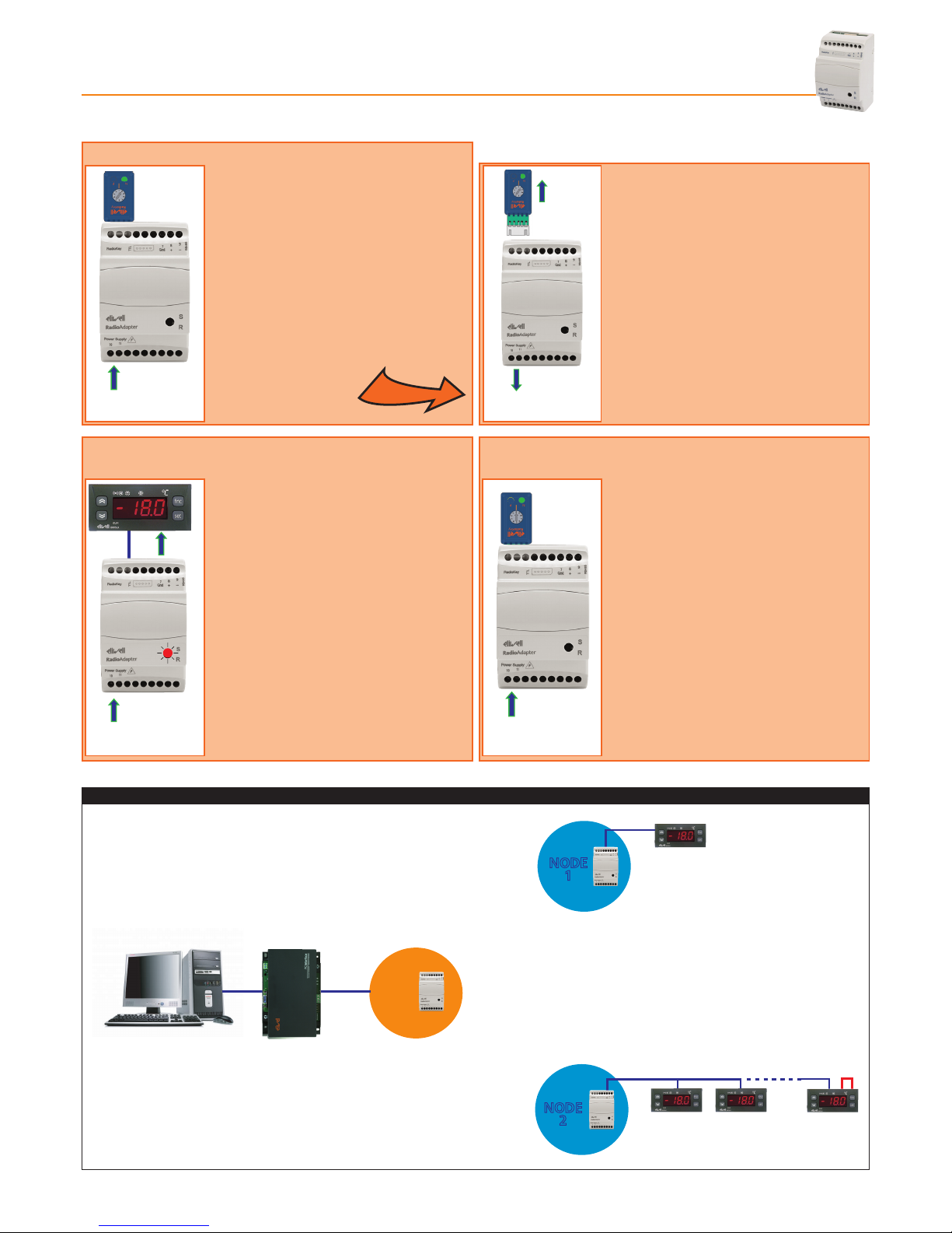
2.2 - HOW TO INSTALL A NODE
2.2.1 - INITIALIZING A NODE
Power
Supply
Power
Supply Power
Supply
Power
Supply
Power
Supply
TTL +
RS485
- Connect the RadioAdapter to the power
supply.
- Set the switch on the RadioKey to
position 1.
- Connect theRadioAdapter to the
RadioKey and wait for the GREEN LED (N)
(on the RadioKey) to light up (YELLOW
LED(P) off). The RadioAdapter is now
configured as a NODE and information
on the type of network is sent to the
NODE.
Power
Supply
Power
Supply
Power
Supply
Power
Supply
Power
Supply
TTL +
RS485
- Disconnect the RadioKey when the
GREEN LED on the NODE starts to
blink.
- Disconnect the NODE from the
power supply.
2.2.2 - ADDRESS CONFIGURATION AND SEARCHING
FOR CONNECTED DEVICES
2.2.3 - SAVING SETTINGS
Power
Supply
Power
Supply
Power
Supply
Power
Supply
Power
Supply
TTL +
RS485
- Configure the Televis or Modbus address
of the devices to be connected to the
NODE.
- Connect the devices to the NODE via TTL
or RS-485.
- Switch on the devices connected and then
the NODE. The NODE will start to scan for
connected devices, which is indicated by
the fast blinking of the GREEN LED on the
NODE.
- The GREEN LED switches off and the RED
LED starts blinking on the NODE when the
scan is complete.
Power
Supply
Power
Supply Power
Supply
Power
Supply
Power
Supply
TTL +
RS485
- Disconnect all devices from the NODE
without switching the NODE off.
- Set the switch on the RadioKey to
position 0 then connect the RadioKey
to the NODE.
- Wait for the GREEN LED (N) on the
RadioKey to light up.
- Disconnect the RadioKey and connect
the devices properly.
IMPORTANT! Repeat the steps outlined above for each NODE to be installed in the network
NETWORK STRUCTURE
PAN-C
NODE
1
NODE
2
TTL/RS-485
RS-485 120 Ω
RS-485
RadioAdapter Pag. 8/12
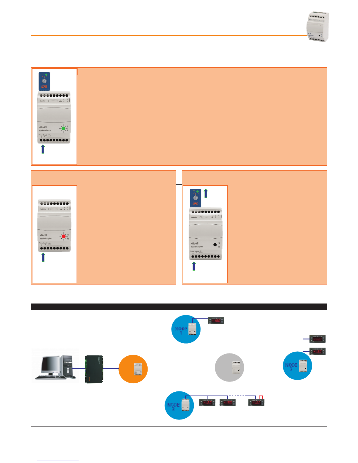
2.3 - HOW TO INSTALL A REPEATER
If two NODES fail to communicate due to the distance the signal has to travel, a repeater can be inserted.
Power
Supply
Power
Supply
Power
Supply
2.3.1 - INITIALIZING A REPEATER
- Connect the RadioAdapter to the power supply.
- Set the switch on the RadioKey to position 1.
- Connect the powered-on RadioAdapter to the RadioKey and wait for the GREEN LED (N) (on the
RadioKey) to light up (YELLOW LED (P) off). The RadioAdapter is now configured as a REPEATER
and information on the type of network is sent to the REPEATER.
- The GREEN LED on the repeater will now start to blink fast.
2.3.2 - SELF-CONFIGURING A REPEATER 2.3.3 - SAVING REPEATER SETTINGS
Power
Supply
Power
Supply
Power
Supply
- Disconnect the RadioKey from the
repeater.
- Wait for self-configuration to complete.
This is indicated when the GREEN LED
switches off and the RED LED starts to
blink
Power
Supply
Power
Supply
Power
Supply
- Connect the RadioAdapter to the
power supply.
- Set the switch on the RadioKey to
position 0
- Connect the RadioKey to the
RadioAdapter and wait for the GREEN
LED (N) on the RadioKey to light up.
- Disconnect the RadioKey.
IMPORTANT! Repeat the steps outlined above for each repeater to be installed in the network
NETWORK STRUCTURE
PAN-C
NODE
1
Repeater
NODE
2
NODE
3
TTL/RS-485
RS-485
RS-485
RS-485
120 Ω
RadioAdapterPag. 9/12
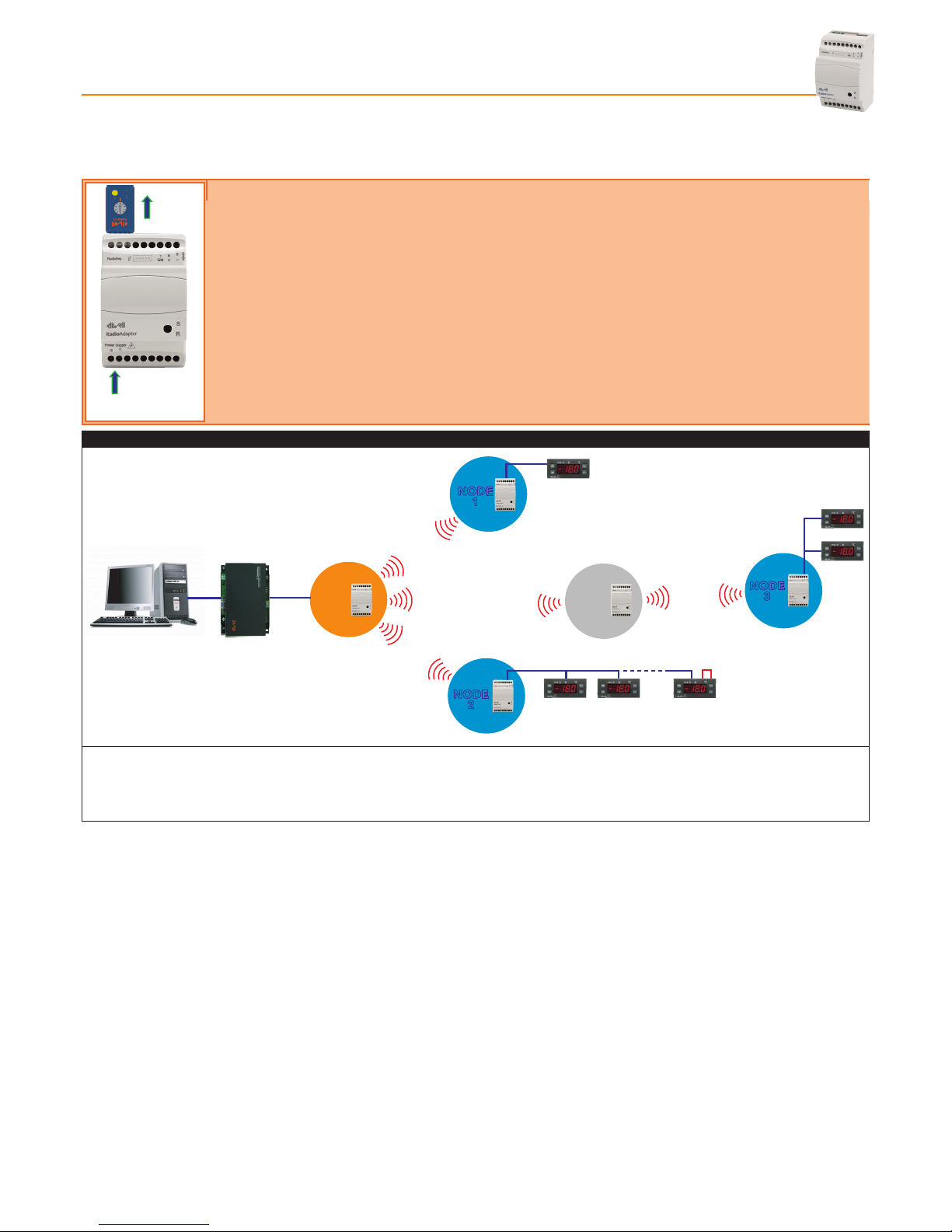
2.4 - CONFIGURING THE PAN-C
After installing the PAN-C and all devices/components have been installed and configured (NODES and any repeaters), the PAN-C
just installed must be configured in order to enable the network.
Power
Supply
2.4.1 - TRANSFERRING NETWORK CONFIGURATION TO THE PAN-C
- Check that the PAN-C is connected to the power supply.
- Check that serial connections (TTL and RS-485) are not connected.
- Set the switch on the RadioKey to position 0
- Connect the powered-on PAN-C to the RadioKey and wait for the YELLOW LED (P) (on the RadioKey) to
light up (GREEN LED (N) off).
- Disconnect the RadioKey from the PAN-C.
- Connect the PAN-C to the PC-Interface or monitoring device via an RS-485 serial port
NETWORK STRUCTURE
PAN-C
NODE
1
Repeater
NODE
2
NODE
3
RS-485
TTL/RS-485
RS-485 120 Ω
RS-485
To enable the network, just switch on the NODES, devices, repeaters and PAN-C.
To start up the monitoring device (Televis or Modbus), refer to the relative user manuals for configuration and use.
NOTA: Communication between NODES, repeaters and PAN-C and the monitoring device will commence after at least 1 minute
has passed after each component of the network was switched on
2.5 - CHANGES TO NETWORK
2.5.1 - ADDING A NEW NODE
Instructions on how to install a new NODE and all relative connections in an existing network are provided below:
- Turn off the monitoring device.
- Install the NODE as described in section “How to install a NODE”
- Repeat the PAN-C configuration as described in section “Configuring the PAN-C”
2.5.2 - ADDING A NEW DEVICE
Instructions on how to install a new device on one of the NODES of an existing network are provided below:
- assign a Televis or Modbus address to the device.
- Connect the new device to the selected NODE.
- Wait for the NODE to finish scanning.
- Disconnect the device from the NODE.
- Set the switch on the RadioKey to position 1
- Connect the RadioKey to the NODE and wait for the GREEN LED (N) on the RadioKey to light up.
The NODE has now reset.
- Disconnect the RadioKey and configure the NODE as explained in section 2.2 How to install a NODE
(ignore the first section 2.2.1 Initializing a NODE).
- Configure the PAN-C again as explained in section 2.4 Configuring PAN-C
RadioAdapter Pag. 10/12
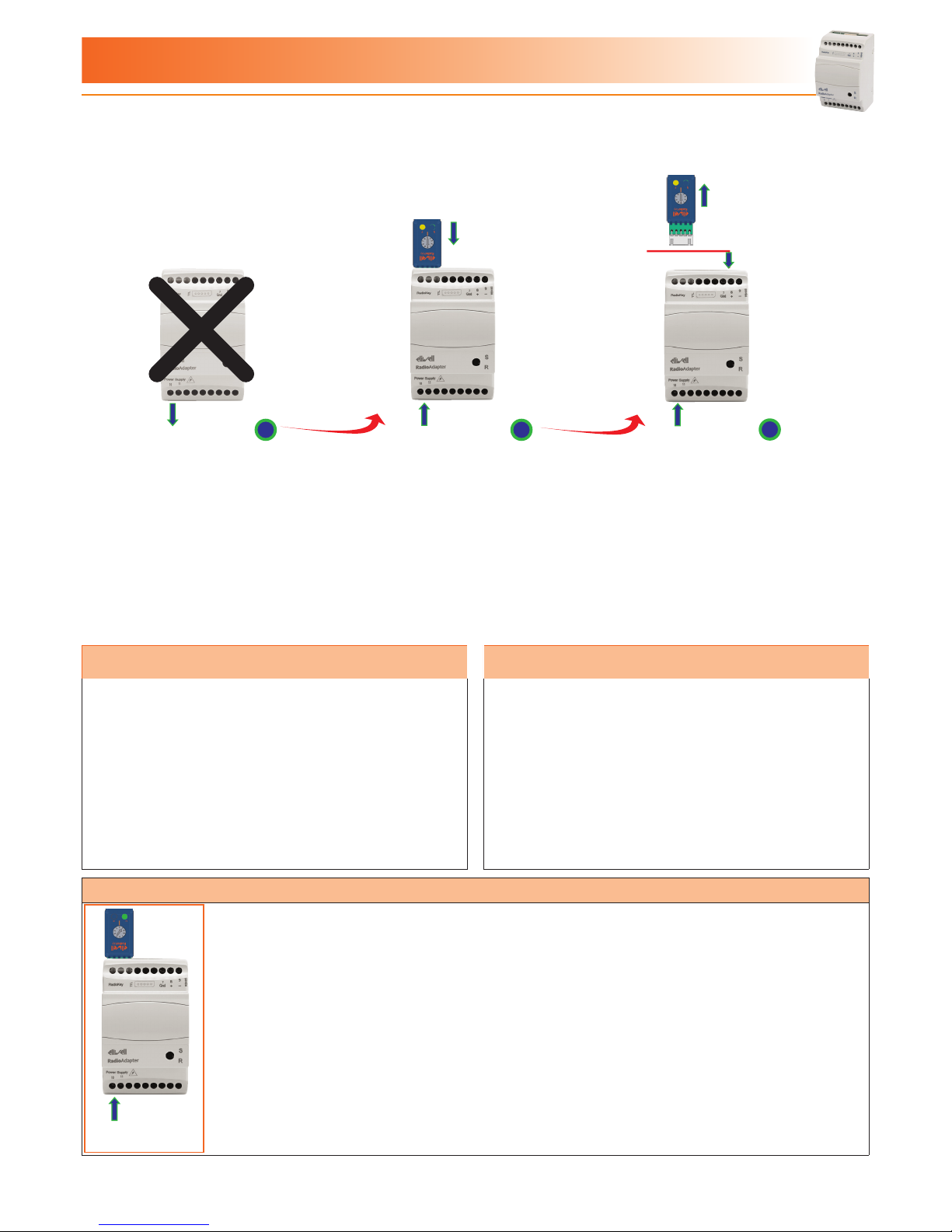
3.1 - REPLACING THE PAN-C
When a PAN-C is found to be faulty, replace it with a new RadioAdapter.
Follow the steps below when replacing a faulty PAN-C with a new one.
Power
Supply
Power
Supply
Power
Supply
Supervisor
1 2 3
1 - Disconnect and remove the faulty
PAN-C.
2 - Place a new RadioAdapter in the
place of the PAN-C just removed.
Set the switch on the RadioKey to
position 5.
Connect the RadioKey to the
RadioAdapter and wait for the
YELLOW LED (P) on the RadioKey
to light up.
3 - Disconnect the RadioKey and
connect the new PAN-C to the
network
3.2 - REPLACING A NODE 3.3 - REPLACING A DEVICE
When a NODE is found to be faulty, the component must be
replaced with a new RadioAdapter.
Follow the steps below when replacing a faulty NODE with a
new one:
- Disconnect and remove the faulty NODE.
- Place a new RadioAdapter in the place of the NODE you
removed.
- Install and configure the new NODE following the steps
outlined in section “How to install a NODE”.
- Repeat the PAN-C configuration as described in section 2.4
Configuring the PAN-C
Follow the steps below when replacing a faulty device with a new
one:
- if the new device has the same address (Televis or Modbus) as
the old one, just connect it to the NODE.
- if on the other hand the new device has a different address
(Televis or Modbus) from the old one, the respective NODE will
have to be Reset (see section “Resetting a NODE”)
3.4 - RESETTING A NODE
Power
Supply
- Disconnect the device from the NODE.
- Set the switch on the RadioKey to position 1.
- Connect the RadioKey to the NODE and wait for the GREEN LED (N) on the RadioKey to light up.
The NODE has now reset.
- Disconnect the RadioKey and configure the NODE following the steps outlined in sections “Address
configuration and searching for connected devices“ and “Saving settings”.
3 - TROUBLESHOOTING
RadioAdapterPag. 11/12
3.5 - CHANGING CHANNEL
If there is disturbance on the network channel which is affecting communication, the channel can be forced to a new one.
A new channel scan can be forced or one of the four pre-selected channels can be set.
3.5.1 - SCANNING TO FIND A NEW CHANNEL
1 - Set the switch on the RadioKey to position 3 Connect the
RadioKey to the PAN-C and wait for the YELLOW LED (P) on the
RadioKey to light up.
2 - Disconnect the PAN-C from the power supply and disconnect
the RadioKey.
Now follow the steps described for the PAN-C in sections ”Channel
search“ and ”Saving PAN-C settings”.
After this, for each NODE follow the steps outlined in section “Saving
Settings“ and for each repeater, the instructions given in section
“Saving repeater settings”.
Power
Supply
Power
Supply
12
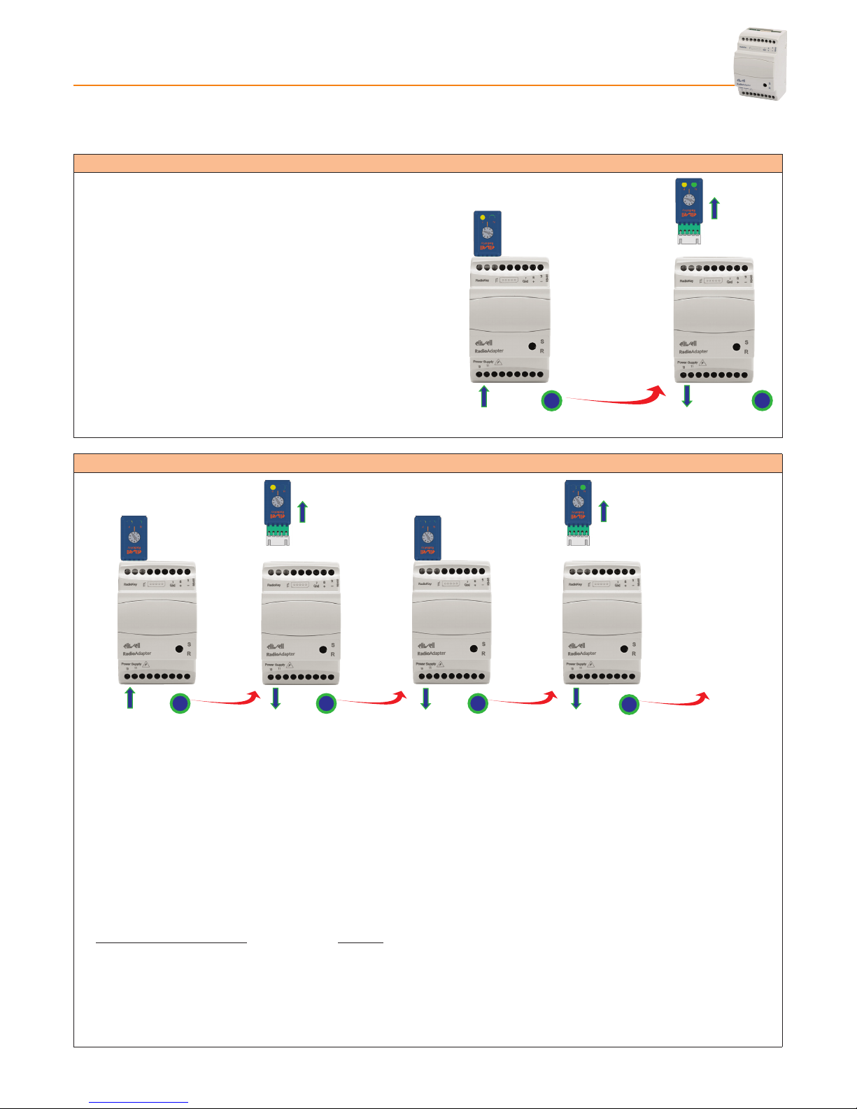
3.5.2 - SETTING COMMUNICATION CHANNEL MANUALLY
Power
Supply
Power
Supply
Power
Supply
PAN-C PAN-C NODE
Power
Supply
NODE
1 2 34
OTHER NODES...
1 - Set the switch on the RadioKey to position 4, 6, 7 or 8 (depending on the channel you want to set).
Connect the RadioKey to the PAN-C and wait for the YELLOW LED on the RadioKey to light up.
2 - Disconnect the PAN-C from the power supply and disconnect the RadioKey.
3 - Leave the switch on the RadioKey in the same position (position 4 in this example).
Connect the RadioKey to a NODE (or to a repeater) that has been powered-on, and wait for the GREEN LED (N) on the
RadioKey to light up.
4 - Disconnect the NODE from the power supply and disconnect the RadioKey.
Repeat the steps listed in points 3 and 4 for each NODE and repeater in the network without changing the setting on the
RadioKey
Position of RadioKey switch Channel
4 12
6 16
7 20
8 25

RadioAdapter Pag. 12/12
Eliwell Controls s.r.l.
Via dell’Industria, 15 • Z.I. Paludi
32010 Pieve d’Alpago (BL) ITALY
Telephone +39 0437 986 111
Facsimile +39 0437 989 066
www.eliwell.it
Technical Customer Support:
Technical helpline +39 0437 986 300
E-mail: [email protected]
Sales
Telephone +39 0437 986 100 (Italy)
+39 0437 986 200 (other countries)
E-mail: [email protected]
4.1 - ELECTRICAL CONNECTIONS
Important! Switch off the device before working on the electrical connections.
The instrument is equipped with screw terminal boards for connection of electrical cables with a diameter of 2.5 mm2 (one conductor
only per terminal for power connections). Make sure that power supply is the correct voltage for the device. TTL serial port cables and
RS-485 serial port cables must be kept separate from the power cables.
The RS-485 network must be appropriately terminated, i.e. by inserting a 120 Ohm terminal resistor between the - and + terminals of
the interface module.
4.2 - DISCLAIMER
This document is the exclusive property of ELIWELL CONTROLS SRL and may not be reproduced or circulated unless expressly authorized
by ELIWELL CONTROLS SRL itself. The same applies to any person or company involved in preparing and editing this document.
ELIWELL CONTROLS SRL reserves the right to amend or improve this document at any time without notice.
4.3 - RESPONSIBILITY AND RESIDUAL RISKS
ELIWELL CONTROLS SRL shall not be liable for damage resulting from:
- Installation/uses other than those specified and, in particular, which do not comply with the safety requirements set out in the
regulations and/or stated herein.
- Use on panels that do not provide adequate protection against electric shock, water or dust when assembled.
- Use on panels that allow access to dangerous parts without having to use tools.
- Tampering and/or modification of the product.
- Installation/use on panels that do not comply with applicable standards and regulations.
4.4 - CONDITIONS OF USE
PERMITTED USE
For safety reasons, the device must be installed and used according to the instructions provided. In particular, parts carrying dangerous
voltages must not be accessible in normal conditions. The device must be adequately protected from water and dust according to the
application, and must also be accessible only using tools (with the exception of the front panel).
Class 4 classification ISA SP100.11 (do not use for safety devices)
USES NOT PERMITTED
The device must not be used for applications other than those described.
Note that the relay contacts provided are of a functional type and therefore subject to malfunction: Any protection devices required by
product standards, or suggested by common sense, must be installed externally to the instrument for obvious safety reasons.
9MAX0010-1 • RadioAdapter • EN • 04/11
© Copyright Eliwell Controls s.r.l. 2011 All rights reserved
4 - WARNINGS
Table of contents
Popular Network Hardware manuals by other brands


... Installation and configuration guide")


AEM
AEM TESTPRO CV100 user manual

Panasonic
Panasonic E series Operation guide

Provision ISR
Provision ISR NVR-16400 user manual

Western multiplex
Western multiplex Tsunami Multipoint Installation and maintenance manual

Recovision
Recovision RV5000 series user manual

2N Telekomunikace
2N Telekomunikace ATEUS STARGATE user manual