Elka E 205 User manual
1. Usage
Electromagnetic bolt E 205 to lock swing gates. The bolt locks either downwards or to the
side.
2. Technical data
Installation and Operating
Instructions
Electromagnetic Bolt E 205
Power supply 24 Vac (Alternating current)
Emergency release With key (cylinder lock)
Maximum current approx. 6,0 A during stroke movement
approx. 1,0 A during stop position
Stroke 50mm
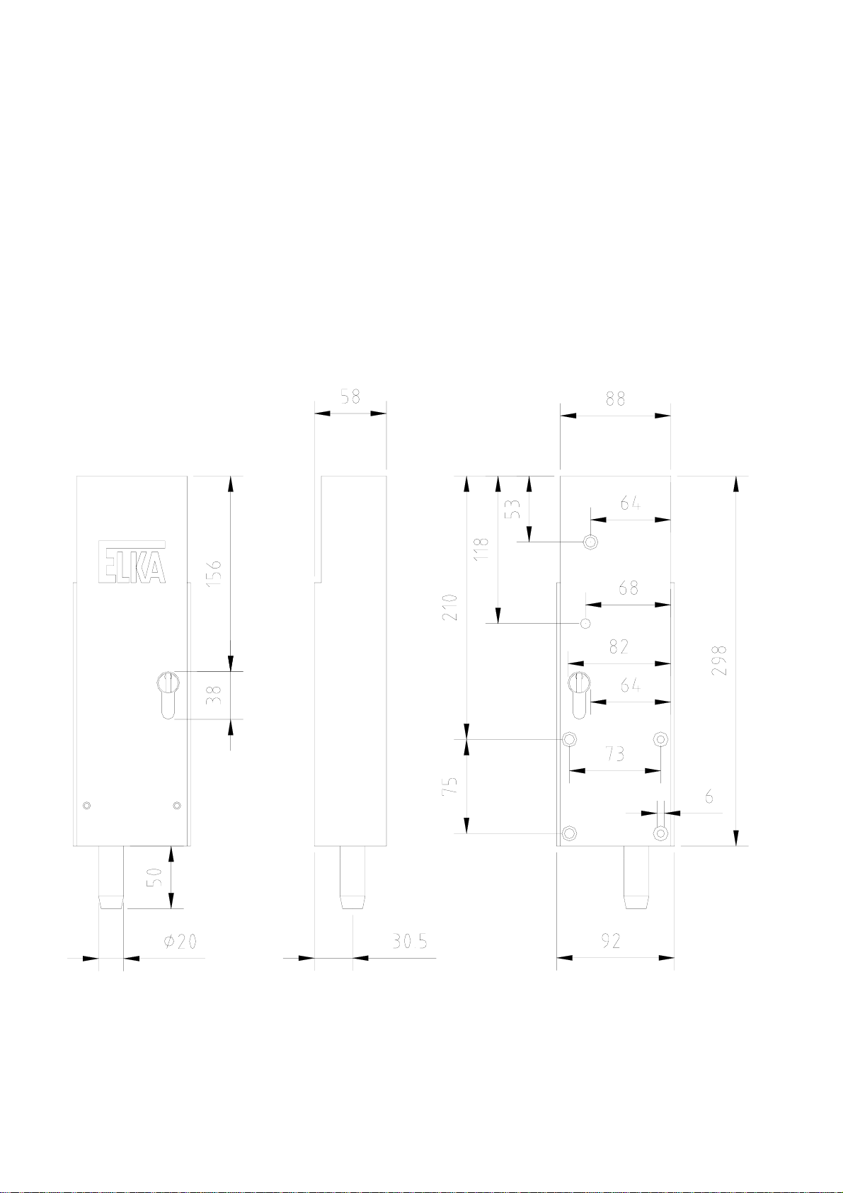
Measurements (W/H/L) 58 x 295 x 94mm
Degree of protection IP 44

© 05.10.2005 ELKA-Torantriebe GmbH u. Co. Betriebs KG Page 2 Electromagnetic bolt E 205
LERN
BTG
BT
AMPEL
PE
N
L1
MO 36
transformer
3.1.1 Electrical connection MO 36 when using without warning light
Directly connectable through the warning light connection and the main transformer of the ELKA controller
MO 36.
Connect the electromagnetic bolt E 205 to the transformer clamp of the main board (secondary winding of
the toroid transformer). The supply of the toroid transformer is switched over one conductor of the warning
light connection.
Please set the pre-warning time for both directions to 4 seconds (learning sequence P8).

© 05.10.2005 ELKA-Torantriebe GmbH u. Co. Betriebs KG Page 3 Electromagnetic bolt E 205
AMPEL
BTG
BT
LERN
PE
L1
N
MO 36
transformer
warning
light
3.1.2 Electrical connection MO 36 when using with warning light
Connect the electromagnetic bolt E 205 to the transformer clamp of the main board (secondary wiring of the
toroid transformer). The supply of the toroid transformer is switched over one conductor of the warning light
connection.
Please set the pre-warning time for both directions to 4 seconds (learning sequence P8).
When warning light and the E 205 shall be used, connect the warning light as shown above.

© 05.10.2005 ELKA-Torantriebe GmbH u. Co. Betriebs KG Page 4 Electromagnetic bolt E 205
V6 V10V4 V8
V11
V9
V7
PE N L1
transformer for E 205
warning light
3.2 Electrical connection MO 32, MO 34 and other controllers
With other controllers the power supply has to come through a separate transformer from a connection,
which is activated at every gate movement, e.g. warning light connection.
Installation example controller MO34
© 05.10.2005 ELKA-Torantriebe GmbH u. Co. Betriebs KG Page 5 Electromagnetic bolt E 205
3.2 General notes
The cross section of the cable to the bolt depends on the distance between the controller and the
electromagnetic bolt:
up to 50m : 1.5mm2
Please note, that with an increasing distance between controller and swing gate the range of the radio
remote control decreases, since the radio remote control receiver is plugged onto the controller.
4. Installation measurements
Locking downwards. The length of the pin is 50mm from the lower end of the electromagnetic bolt.

© 05.10.2005 ELKA-Torantriebe GmbH u. Co. Betriebs KG Page 6 Electromagnetic bolt E 205
5. Emergency release during power failure
Release the bolt by turning the key clockwise (approx. 4 turns) until the pin has reached his upper position.
Engage by turning the key counter-clockwise. The enclosed single cylinder lock can be replaced by another
single cylinder lock or by a double cylinder lock on site (e.g. from a locking system). When using a double
cylinder lock the lock can be released from inside or outside the gate as long as there is an opening for the
double profile cylinder in the gate leaf.
6. General notes of safety
These operating instructions must be available on site at all times. It should be read thoroughly by all
persons who use, or service the appliances. Improper usage or servicing or ignoring the operating
instructions can be a source of danger for persons, or result in material damage. If the meaning of any part
of these instructions isn’t clear, then please contact your supplier before you use the appliance.
This applies to all setup procedures, fault finding, disposal of material, care and servicing of the appliance.
The accident prevention regulations and applicable technical regulations (e.g. safety or electrical) and
environment protection regulations of the country in which the appliance is used also apply.
All repairs on the appliances must be carried out by qualified persons. The supplier accepts no liability for
damage which is caused by using the appliance for purposes other than those for which it is built.
The supplier cannot recognise every possible source of danger in advance. If the appliance is used other
than in the recommended manner, the user must ascertain that no danger for himself or others will result
from this use. He should also ascertain that the planned use will have no detrimental effect on the appliance
itself. The appliance should only be used when all safety equipment is available and in working order. All
faults which could be a source of danger to the user or to third persons must be eliminated immediately. All
Warning and Safety notices on the appliances must be kept readable.
All electrical periphery equipment which is connected to the appliance must have a CE Mark, which ensures
that it conforms to the relevant EEC regulations. Neither mechanical nor electrical alterations to the
appliance, without explicit agreement of the manufacturer, are allowed. All alterations or extensions to the
appliance must be carried out with parts which the supplier have defined as suitable for such alterations, and
be carried out by qualified personnel.
Any contravention of these conditions revokes the manufacturer’s guarantee and also the CE Mark and the
user is alone responsible for the consequences.
Our service department is available to answer all queries about these conditions and, of course, about our
appliances.
We reserve the right to make technical improvements without prior notice.
des Fortschritts vorbehalten
The operation of the system within CEN countries must also be conformant with the European safety-relevant
directives and standards.
Other manuals for E 205
1
Other Elka Lock manuals


Popular Lock manuals by other brands

XLOCK
XLOCK 102 installation guide

S&G
S&G 2740 operating instructions

Kwikset
Kwikset Powerbolt2 installation guide

Major Manufacturing
Major Manufacturing HIT-45 Instructions for installation

M-LOCKS
M-LOCKS EM3020 Mounting instructions

Borglocks
Borglocks BL2615MG Parts List, Installation and General Information


