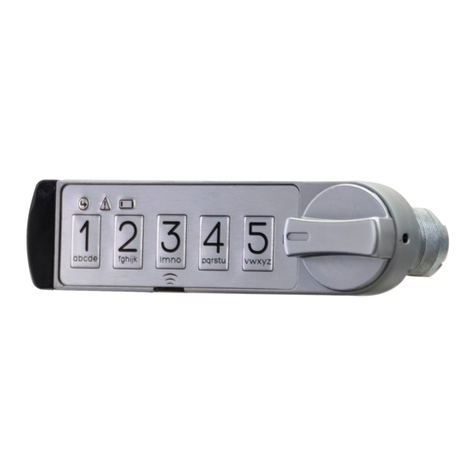
TriTeq MicroIQ UM User manual

.39
1.00
3.86
Fig. 2
The installation template at the end of this manual can be used to drill a mounting
hole for the MicroIQ. Wood screw or self-tapping metal screw options are provided.
In addition, double stick tape can be used solely or in conjunction with the mounting
screw to further secure the lock. Allow tape to cure for 72 hours.
Prior to installation and insertion of the battery, the knob of the lock mechanism will
be free moving. The MicroIQ hardware contains a cam stop (#6) for both 90 and for
180 degrees. Select and install the desired cam stop and cam(#7). Position the cam
stop so the knob rotation is clockwise or counter-clockwise as desired.
1
Contents
1
R
O
TM
UTILITY LOCK - MODELS: UT UM UA
Installation Manual
FOR OFFICE FURNITURE, STORAGE CABINETS, LOCKERS, SAFES, VAULTS, SECURED ENCLOSURES
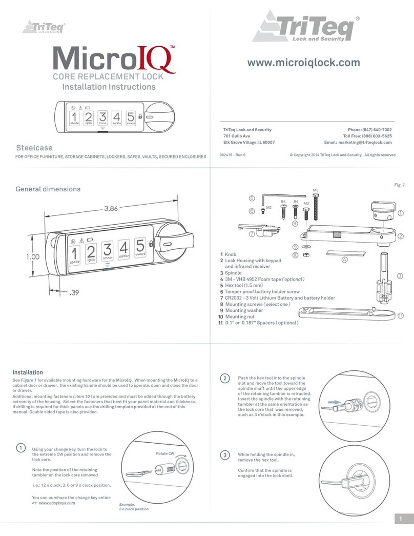
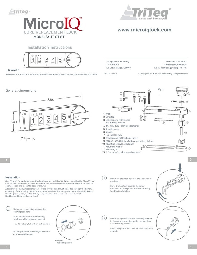
See Figure 1 for available mounting hardware for the MicroIQ. When mounting
the MicroIQ to a cabinet door or drawer, a separately mounted handle should be
used to operate, open and close the door or drawer.
Installation
When installing the lock to the cabinet/drawer, you have the option to fasten the
lock body with a nut or a retaining clip. A ‘wonder’ washer (#3) is provided for
installation in a drilled hole through either wood or metal panels.
Additional mounting fasteners (10) and/or double sided tape are provided and
must be added through the battery extremity of the housing. Select the fasteners
that best fit your panel material and thickness. If drilling is needed for thick
panels, drilling template provided on page 13.
14
1
13
11
2
Fig. 1
10
15
#4
M3
M3
Lock Housing with keypad and infrared receiver
Cap with cover
1
2
3
4
5
6
7
8
9
10
11
12
13
14
15
Locking cam (per request)
Clip spring
Cam nut (not provided with 3/8” shell)
Cam screw
Mounting screws (only 1 needed)
Mounting nut
Mounting washer
180° Cam stop
90° Cam stop
Adapter (USE ADAPTER P/N 13346 FOR 9mm CAM HOLE EUROLOCK)
Hex tool (1.5mm)
Temper proof battery holder screw
3M - VHB 4952 Foam tape (optional)
12
4
3
5
6
7
8
9

Operation
1-2-3-4-5 keypad buttons: For entering and programming lock codes.
Program button: Initiate the lock programming mode by pressing the front thin edge of the black button inward toward the mounting surface the MicroIQ is mounted to.
Infrared Receiver:
The Infrared Receiver will receive a signal from an electronic TriTeq key-fob when
it is pointed at the receiver located behind the Program button. The Program
button is slightly opaque so the key-fob signal will penetrate the button.
Knob:
To move the lock mechanism 90 or 180 degrees clockwise or counterclockwise from
the locked and unlocked states.
The Green and Red LED’s will flash and illuminate to indicate operating conditions
per the descriptions below.
The Yellow LED will flash 5 times after the lock is operated to signify the
battery level is low and should be replaced.
Green
Proceed
LED
Red
Error
LED
Yellow
Low battery
LED
Knob
in locked
position
Location to
point the
key-fob
Battery
holder
with cover
Keypad
Fig. 5
Program
button
Push thin
front edge
inward
Press
Here
R
The mounting screw for the Lock Housing must be installed before
installing the MicroIQ battery.
1
2
Battery
If mounted on sheet metal :
If mounted to wood panel with
threaded insert:
Select appropriate mounting screw. If a lock
spacer is required, a mounting screw must be
#4 Sx.375 sheet-metal screw
M3 x25mm (1”) screw
In addition, the double stick tape can
be used solely or in conjunction with
the mounting screw to further secure
the lock. Allow tape to cure for 72 hours.
Fig. 3
2 3
56
Battery
Holder
Battery
Cover
LIFT
UPWARD
1
4
Battery
Holder
Battery
Strip
(optional)
Battery
Strip
(optional)
SWING OVER
AND SNAP THE
COVER DOWN
PULL SRTIP
BEFORE USING
Hex
Tool
Screw
Battery
Strip
(optional)
Battery
Strip
(optional)
NOTE: If the assembled lock is going to be transported or
shipped, it is required that the battery assembly includes the
battery strip. If the lock is being set up for use, the battery
strip is not needed (skip step 1 and 6).
Rotate the knob to the unlocked position
Insert the battery strip into the housing.
Insert the battery holder assembly (battery, holder, and
cover) into the lock housing making sure the cover is
open. If the assembly is not fully seated, make sure the
battery holder screw is flush with the bottom of the
assembly and that it is not interfering with the fit.
Insert the provided M2 screw in the battery holder.
Use the hex tool to attach the battery assembly to the
lock housing.
Swing the battery cover closed and snap in place.
If transporting/shipping the lock assembly, the battery
strip must be removed prior to use. Remove by pulling
the strip out of the housing.
1
2
3
4
5
6
7

Liability Limits:
Operating Temperature: 0 - +50 C
Storage temperature: -10 - +70 C
Operating Moisture: 20% - 80% Rh
(without condensation)
Replacement Battery: 3 volt lithium CR2032
This is a limited warranty and in lieu of all other warranties (including the implied warranties
of merchantability and fitness of use) and under no circumstances shall TriTeq Lock & Security
or Hudson Lock, LLC be liable for any incidental or consequential damages or losses.
To clean the MicroIQ surface, apply a non-acid based cleaner to a clean cotton cloth. Do not spray
cleaner directly on the MicroIQ. Wipe down the keypad and housing surface of excess cleaner.
TriTeq Limited Warranty:
TriTeq offers a one year limited warranty all products to be free from manufacturing defects
in materials and workmanship. This limited warranty does not cover battery, lost combinations
or damages caused by improper mounting, improper or unreasonable use.
Care and Cleaning:
TriTeq Lock and Security
701 Gullo Ave
Elk Grove Village, IL
60007
Phone: (847) 640-7002
Toll Free: (888) 603-5625
Email: marketing@triteqlock.com
Battery Life: 3 to 5 years typical or 50,000 operations
ATTENTION: Battery life may vary with battery brand
and environmental conditions.
© Copyright 2014 TriTeq Lock and Security. All rights reserved
13018 - Rev. 3 S-L
Mounting Template
3.150
.75
1.00 Measure before drilling.
If the length of the segment is dierent from 1.00"
the template dimensions will be scaled accordingly
As an option, the lock can be operated with the one blue remote key-fob and up to two black remote User key-fobs.
For further instructions about programming and operating the MicroIQ, please refer to the“MicroIQ Programming” manual or
watch the videos on our website, www.MicroIQLock.com
1
3
When entering the Factory code, the Supervisor code or User code,
you should hear a ‘click’ sound, the green LED will light up turn the
knob to unlocked position.
To unlock MicroIQ using a code:
Turn the knob from the unlocked position to the locked position,
listen for the lock mechanism to operate by hearing a “click”
sound, confirm the knob is locked.
To re-lock MicroIQ:
1/8” diameter hole for metal
3/32” diameter hole for wood
Other manuals for MicroIQ UM
1
This manual suits for next models
2
Other TriTeq Lock manuals
