ELKHART BRASS Scorpion RF 8294-06 Assembly instructions

E
E
L
LK
KH
HA
AR
RT
T
B
B
R
RA
AS
SS
S
M
M
F
FG
G
.
.
C
C
O
O
.
.,
,
I
I
N
NC
C
.
.
1302 WEST BEARDSLEY AVENUE •P.O. BOX 1127 •ELKHART IN 46515 •(574) 295-8330 •FAX (574) 293-9914
98291000 Rev.A
Installation, Operating, & Maintenance Instructions
Model 8294-06, 8294-06 EXT, and 8394-07
Monitors

System Information:
Monitor Serial Number: ___________________________________________
Monitor Accessories (nozzle gallonage and type, types of transmitters, Etc.) :
_________________________________________________________________
_________________________________________________________________
_________________________________________________________________
_________________________________________________________________
_________________________________________________________________
_________________________________________________________________
_________________________________________________________________
_________________________________________________________________
_________________________________________________________________
_________________________________________________________________
_________________________________________________________________
_________________________________________________________________
_________________________________________________________________
_________________________________________________________________

TABLE OF CONTENTS
I. PRODUCT SAFETY......................................................................................................................1
II. SYSTEM FEATURES ...................................................................................................................2
III. SYSTEM COMPONENT DESCRIPTIONS ...............................................................................4
A. 8294-06 AND 8394-07 SCORPION RF MONITORS........................................................................................................ 4
B. 8294-06 EXT SCORPION RF MONITOR....................................................................................................................... 4
C. RF RECEIVER/CONTROL MODULE.............................................................................................................................. 5
D. RF TRANSMITTERS ..................................................................................................................................................... 6
1. 81282001 Handheld RF Transmitter..................................................................................................................... 6
2. 81327011 Primary Panel Mount RF Transmitter ................................................................................................. 7
3. 81327001 Secondary Panel Mount RF Transmitter.............................................................................................. 7
4. 81353011 OEM Primary RF Transmitter ............................................................................................................. 7
5. 81353001 OEM Secondary RF Transmitter.......................................................................................................... 7
6. 81340001 Secondary Switch Box Control for Aerial Applications ....................................................................... 8
7. 81392001 Auxiliary Battery Pack ......................................................................................................................... 8
IV. CONTROL SYSTEM SPECIFICATIONS.................................................................................. 9
V. INSTALLATION INSTRUCTIONS..........................................................................................10
A. COMPONENT MOUNTING .......................................................................................................................................... 10
1. Monitor................................................................................................................................................................ 10
2. Monitor Wiring.................................................................................................................................................... 12
3. 81327001 and 81327011 Panel Mount RF Transmitter...................................................................................... 12
4. 81353001 And 81353011 Fixed Remote for Use with OEM Supplied Switches.................................................. 12
5. 81340001 Secondary Switch Box Control for Aerial Applications ..................................................................... 12
6. 81392001 Auxiliary Battery ................................................................................................................................ 13
B. COMMUNICATION ADDRESS SETUP .......................................................................................................................... 14
C. RF SETTINGS ............................................................................................................................................................ 14
1. RF Receiver/Control Module Settings................................................................................................................. 15
2. 81282001 Handheld RF Transmitter Settings..................................................................................................... 15
3. 81327001, 81327011, 81353001 and 81353011 Secondary, Primary, Panel Mount, and OEM RF Transmitters
16
D. STOW POSITION PROGRAMMING............................................................................................................................... 17
1. Programming Stow Position ............................................................................................................................... 17
2. Rotational Limit Settings..................................................................................................................................... 17
VI. OPERATING INSTRUCTIONS.................................................................................................20
A. NORMAL OPERATION................................................................................................................................................ 20
B. OSCILLATION FUNCTION........................................................................................................................................... 20
C. MANUAL OVERRIDE ................................................................................................................................................. 21
D. STORING THE MONITOR............................................................................................................................................ 21
VII. MAINTENANCE & INSPECTION ...........................................................................................22
A. MONITOR.................................................................................................................................................................. 22
1. Preventive Maintenance...................................................................................................................................... 22
2. Understanding the Controller LEDs................................................................................................................... 22
B. HANDHELD TRANSMITTER........................................................................................................................................ 23
1. Battery Type........................................................................................................................................................ 23
2. Battery Replacement ........................................................................................................................................... 23
VIII. REPAIR PARTS................................................................................................................... 24
IX. MONITOR & NOZZLE HYDRAULIC DATA........................................................................30


1
I. PRODUCT SAFETY
Important:
Before installing and operating this equipment, read and study this manual thoroughly. Proper
installation is essential to safe operation. In addition, the following points should be adhered to
in order to ensure the safety of equipment and personnel:
1. All personnel who may be expected to use this equipment must be thoroughly
trained in its safe and proper use.
2. Before flowing water from this device, check that all personnel (fire service
and civilian) are out of the stream path. Also, check to make sure stream
direction will not cause avoidable property damage.
3. Become thoroughly familiar with the hydraulic characteristics of this
equipment, and the pumping system used to supply it. To produce effective
fire streams, operating personnel must be properly trained.
4. Whenever possible, this equipment should be operated from a remote location.
Do not needlessly expose personnel to dangerous fire conditions.
5. Open water valve supplying this equipment slowly, so that the piping fills
slowly, thus preventing possible water hammer occurrence.
6. After each use, and on a scheduled basis, inspect equipment per instructions in
section VII.
7. Any modifications to the enclosure will destroy the NEMA 4 rating and void
warranty coverage of the enclosure and all components within.

2
II. SYSTEM FEATURES
Figure 1
8294-06 w/284-A Stream Shaper and SM-2000E Nozzle shown
* 3rd wire provided for optional customer provided stow indicator lamp.
Optional SM-2000E
Fog Nozzle
284A Stream Shaper
Full Vane Cast
Aluminum or
Brass Waterway
Up to ¼ Mile Range
Relay/Receiver
Box Is Integral
With Monitor.
(No Separate
Control Box to
Install.)
Billions of
Security Codes
and Frequency
Combinations
Horizontal and
Vertical Rotation
*Simple 2 Wire
Installation
4” 150# ANSI Flange
Remotely Programmable
Oscillation Function
Manual Override
Capabilities

3
Power
Indicator
Figure 2
81282001 Handheld RF transmitter Features
PUSH AND H OLD
STOW AND FOG
TOGETH ER
TO ACT IVATE
Two-Button Stow
Function OnlyActivated
by Primary Control
N
EMA 4 Seale
d
N
o Control
Wires to Run
Primary Control
Overrides
Handheld and
Secondary
Flush Mount
Hardwired to
Vehicle Power
System
N
EMA 4 Seale
d
N
o Control
Wires to
Run
Flush
Mount
Hardwired to
Vehicle Power
System
(Maximum
current draw is
500 mA)
Figure 3
81327011 Primary Panel Mount
Control Features
Figure 4
81327001 Secondary Panel Mount
Control Features
Figure 5
81340001 Secondary Switch Box Control

4
III. SYSTEM COMPONENT DESCRIPTIONS
A. 8294-06 and 8394-07 Scorpion RF Monitors
(Figure 6) The 8294-06 Scorpion is a cast aluminum monitor with
4" waterway while the 8394-07 is cast brass. The waterway
contains a central vane to minimize large-scale turbulence and
provide superior fire streams. Monitor water supply connection is
a 4 inch 150 lb. ANSI pattern flange. The discharge nozzle
connection is 3-1/2 inch National Hose thread. Nozzle stream
direction is controlled by two permanent magnet type planetary
gear motors, one controlling rotation about the axis of the water
inlet, and the other controlling nozzle elevation and depression.
Right angle gear cases between the gear motor and the monitor
allow for convenient manual override of the electric motors in the
event of a power failure during firefighting operations. All
gearing is enclosed within the monitor housings.
The maximum monitor flow capacity is 2000 gallons per minute.
Monitors can be supplied with the SM-1250E (SM-
1250BE for model 8394-07) constant pressure (automatic) type
master stream nozzle. This nozzle has a flow range of 300 to
1250 gallons per minute at 75 psi and has an electric drive
mechanism for RF control of the spray pattern from a straight
stream to wide fog. A similar nozzle, the SM-2000E (SM-
2000BE for 8394-07), provides a flow range of 500 to 2000
gallons per minute at 80 psi. For optimum straight stream
performance, stream shapers are provided as part of the monitor
and nozzle system. Solid stream nozzles are also available for use
with these monitors.
Figure 6
8294-06 Monitor with 284-A
and SM-2000E
B. 8294-06 EXT Scorpion RF Monitor
The extended travel Scorpion has the same highly efficient waterway and flow capacity as the
Scorpion RF monitor. The monitor waterway is supplied through a 4” 150# flat faced flange base.
The 8294-06 EXT monitor has a mechanical stop to allow 180º for added protection in an aerial
application.
The extended travel Scorpion RF has special features to optimize performance as an aerial master
stream device when used on a straight aerial ladder with pinnable waterway. The pinnable waterway
feature allows the waterway to be pinned to the second fly section of the ladder (egress position), thus
keeping the monitor and nozzle away from the end fly section when it is necessary to place the ladder
tip at a window sill or roof parapet.
The 8294-06 EXT contains a special wiring harness connection at the inlet flange to allow attachment
of an OEM provided proximity sensor. The proximity sensor is used to tell the monitor controller
which positions the waterway and monitor is. As a result, the monitor discharge Up-Down travel
range differs for the two waterway and monitor positions as indicated in Table 1.

5
Waterway/Monitor Position Up-Down Travel Range
Master Stream +80º to -135º
Egress 0º to –135º
Table 1
The 0º position is when the nozzle is aimed parallel to the ladder.
As a further enhancement, the left-right motor direction of rotation automatically reverses when the
monitor discharge is in the range of 0º to +80º. Without this feature, when the discharge travels above
0º, “left” would functionally become “right” and vice versa.
If the proximity sensor changes state while the monitor is in the “master stream” position and the
monitor discharge is in the 0º to 80º “up” range, the monitor controller will automatically lower the
discharge to 0º to prevent possible interference with the ladder, or impingement of stream upon
personnel.
Figure 7
8294-06 EXT Monitor
.
C. RF Receiver/Control Module
The monitor control circuit uses a state-of-the-art PIC (Programmable Integrated Circuit) chip design.
This device allows numerous control features while keeping circuit board size to a minimum. Relays
within this box provide motor reversing control for the Up/Down, Left/Right and Straight Stream/Fog
functions.
All functions are sent to the RF Receiver/Control Module via an encoded radio frequency link. The
radio link reduces the number of control wires down to just the two power leads, dramatically
simplifying the installation procedure. The link also allows wireless control up to ¼ mile away using a
battery powered handheld transmitter.

6
An encoder, part of the horizontal motor, provides horizontal motion control feedback. The counter in
combination with the PIC controller enables the monitor to oscillate between programmable endpoints
that are set directly from the remote transmitter.
The encoder enables the PIC controller to remember a home or stow position. This stow position can
be used as a storage position for the monitor during transport. Once the “Stow” feature is activated,
the monitor will automatically return to the home or stow position.
The control system also provides secondary motor protection with the use of electronic current sensing
circuitry. If the monitor encounters an obstruction before reaching a limit, this circuitry quickly senses
motor stall current and automatically shuts off power to the motor. As soon as the control switch is
released, the circuit resets to allow subsequent operation of the monitor.
Caution:
Any modification of the enclosure will destroy the NEMA 4 rating and will void the warranty coverage
of the RF Receiver/Control Module.
The following additional functions/features are provided in the RF Receiver/Control Module:
Reverse Polarity Protection: If battery connections are reversed, this feature prevents
power from being applied to circuits, and prevents damage to electronic components.
Circuit Board Moisture Protection: The circuit board and circuit components are
protected from moisture by an acrylic resin conformal coating. All relays have sealed
covers.
D. RF Transmitters
The 8294-06, 8294-06 EXT, and 8394-07 monitors use W.E.T. (Wireless Electronic Technology), an
innovative wireless radio link, to send all commands from the RF transmitters to the monitor
controller. This new wireless link gives the operator the ability to view the discharge stream and target
from virtually any point of view within ¼ mile of monitor.
1. 81282001 Handheld RF Transmitter
(Figure 8) A sealed handheld RF transmitter contains all the
controls necessary for operation of the monitor. The
handheld remote allows the operator to direct the monitor
from a significantly improved point of view. With the
wireless remote, the operator can view the stream from the
side and confirm that the stream is hitting its target.
Separate push button switches are provided for up, down,
left, right, fog, and stream functions. The handheld remote
has user selectable frequency and security codes that allow
multiple monitors to operate on the same fire ground at the
same time. The remote has an automatic power down
feature that will shut down the power after 5 minutes of no
activity. As an additional power saving feature the radio
signal is only transmitted while a button is pushed. The
handheld remote case has a NEMA 4 rating.
Figure 8
81282001 Handheld RF Transmitter

7
2. 81327011 Primary Panel Mount RF
Transmitter
(Figure 9) The fixed RF transmitter sends signals to the
monitor via an encoded radio signal, requiring no wires
between the RF transmitter and the monitor. It is powered
by the 12V or 24V vehicle electrical system. The faceplate
is intended for a flush mount onto the pump or aerial ladder
control panel. Separate sealed push button switches are
provided for up, down, left, right, fog, and stream functions.
This fixed RF transmitter provides two-button access to the
Stow feature. It will override any low-priority controls,
allowing the apparatus operator to retain ultimate control
over the monitor.
3. 81327001 Secondary Panel Mount RF
Transmitter
(Figure 10) The fixed RF transmitter sends signals to the
monitor via an encoded radio signal, requiring no wires
between the RF transmitter and the monitor. It is powered
by the 12V or 24V vehicle electrical system. The faceplate
is intended for a flush mount onto the pump or aerial ladder
control panel. Separate sealed push button switches are
provided for up, down, left, right, fog, and stream functions.
Figure 9
81327011 Primary Panel Mount RF
Transmitter
Figure 10
81327001 Secondary Panel Mount RF
Transmitter
4. 81353011 OEM Primary RF Transmitter
(Figure 11) The OEM RF transmitter allows the monitor
installer to use their switching arrangement while still
having the benefit of the W.E.T. It has all of the same
features of the Primary Panel Mount RF transmitter, but has
a wiring harness for the installer to connect to the switches.
5. 81353001 OEM Secondary RF Transmitter
(Figure 11) The OEM RF transmitter allows the monitor
installer to use their switching arrangement while still
having the benefit of the W.E.T. It has all of the same
features of the Secondary Panel Mount RF transmitter, but
has a wiring harness for the installer to connect to the
switches.
Figure 11
81353011 and 813530001
OEM RF Transmitter

8
6. 81340001 Secondary Switch Box
Control for Aerial Applications
(Figure 12) This component is a surface mount type
switch box with controls for operation of the monitor for
use with the OEM secondary RF transmitter. Separate
sealed toggle switches are furnished for up-down, left-
right, and strt-fog functions. The box has a NEMA 4
rating, and is generally installed at the tip of the aerial
ladder, or in the bucket of the aerial platform. A
terminal strip inside the enclosure allows for connection
of the control cable, and a watertight strain relief fitting
provides for sealing around the cable entry.
7. 81392001 Auxiliary Battery Pack
A 12-volt, 12 amp-hr. sealed lead-acid battery pack is
available to allow operation of the monitor in case of
vehicle electrical system failure. These battery packs are
also used as a means to minimize the required size of
conductors routed up aerial ladders and towers. This is
accomplished by mounting the battery pack near the
monitor, with a small trickle-charge conductor to the
battery from the vehicle system.
Figure 12
81340001 Secondary Switch Box Control
Figure 13
81392001 Auxiliary Battery Pack
Caution: Any modification of the enclosure of any of the transmitters or switch box control
will destroy the NEMA 4 rating, and will void the warranty coverage of the RF transmitter. Ensure all
O-ring and gaskets are properly installed when closing receiver or controller enclosures.

9
IV. CONTROL SYSTEM SPECIFICATIONS
Handheld Transmitter Specifications
•Input power 2 AA batteries (Alkaline recommended)
•Output power Meets FCC part 15 requirements for license free
operation
•Transmitter dimensions 6” x 3 1/4” x 1 3/8”
•Transmitter weight 10 ½ oz.
•Operating temperature range -40ºF to 150ºF (-40ºC to 65ºC)
•FCC ID QT8PTSS2003
Fixed Transmitter Specifications
•Input power 12 VDC (11VDC to 14 VDC)
•Output power Meets FCC part 15 requirements for license free
operation
•Transmitter dimensions 7 5/8” x 3 7/8” x 2 3/8”
•Operating temperature range -40ºF to 150ºF (-40ºC to 65ºC)
•FCC ID QT8PTSS2003
Receiver Specifications
•Power requirements 12VDC (11VDC to 14VDC) at the controller under
full load
•Control current
•Operating temperature range 0.07 A*
-40ºF to 150ºF (-40ºC to 65ºC)
Table 2
Motor Current Specifications
Monitor Left/Right Up/Down Nozzle
Run I 1.0-1.5 A* at 200 psi 1.0 A* at 200 psi 0.5 A
Stall I 33.3 A 33.3 A NA
Current Trip Point 13 A 10 A 4 A
Shock:
•30 G's (55 Hz. @ .2 inch double amplitude).
Vibration:
•15.5 G's (55 Hz. @ .05 inch double amplitude) continuous operation.
Drop Test:
•The handheld transmitter must meet operating specifications after drop from 1-meter height onto
concrete surface.
Environmental:
•All enclosures have a NEMA 4 rating (must withstand a 1 inch stream of water (65 gpm) from a
distance of ten feet for five minutes, with no water entering the enclosure).
*All current ratings are at 12 volts

10
V. INSTALLATION INSTRUCTIONS
A. Component Mounting
1. Monitor
a) 4” NPT Base: Apply an appropriate thread sealant to the 4” NPT nipple. Thread the
monitor base onto the nipple. Install with the "straight ahead" position properly aligned.
b) 4” 150# Flat Faced Flanged: Attach 4" 150 lb. class ANSI pattern companion flange to
water supply pipe so that bolt pattern will allow monitor to be installed with the "straight
ahead" position properly aligned. Alignment is correct when the "straight ahead" direction is
centered between adjacent flange holes. Attach monitor inlet flange to companion flange on
water supply pipe with eight (8) 5/8-11 UNC grade 5 carbon steel or stainless steel bolts, 2-1/2
inches long, with nuts. If a wafer type butterfly valve is installed between the monitor and the
companion flange, required bolt length will be 4-1/2 inches. Seal flange joint with gasket, or
suitable flange sealant. Most wafer type butterfly valves have seats that serve as flange
gaskets, and separate gaskets or sealant is not required. Apply Loctite® #242 to bolt threads,
then thread on nuts, and torque to 60-70 ft-lbs.
Warning: When installing monitor on a raised face companion flange, it is critical that
bolts be tightened uniformly to prevent cocking of the monitor relative to the flange or valve. If the
monitor becomes cocked, (see Figure 14) the monitor cast flange base will fracture and fail when the
bolts on the "high" side are tightened.
Figure 14
Improper Flange Installation

11
Figure 15
81327001 and 81327011 Fixed RF Transmitter Panel Template

12
2. Monitor Wiring
a) Place a 10A fuse for the 8294-06 and 8294-06 EXT monitors and a 15A fuse for the 8394-07
monitor between the red lead (pin C) of the monitor and a switched positive power lead on the
vehicle. Attach the black lead (pin A) from the monitor base to the vehicle ground.
b) The white lead (pin B) is for an optional “Stow indicator” which could be attached to a relay or
LED supplied by the OEM. The circuit switches in a ground and is limited to 250 mA of current
when the monitor is in a non-stowed position.
c) All control functions are sent to the monitor via an encoded RF signal from the RF transmitter;
no control wiring is needed.
d) The 8294-06 EXT has a proximity sensor. The red wire (pin C) supplies power. The black
lead (pin A) is ground. The white lead (pin B) is a signal for the proximity sensor to show master
stream versus an egress position.
3. 81327001 and 81327011 Panel Mount RF Transmitter
a) Mark the panel cutout and mounting screw pattern per dimensions in Figure 15
b) Cut a rectangular clearance opening and drill four ∅0.219” (7/32” drill) holes.
c) Insert fixed RF transmitter case through panel cutout. Secure the unit to the panel with four
#10-32 screws. The length of the screws should be the panel thickness plus 3/16”. The screws
supplied are ¼” in length. Apply Loctite #242 to the threads of the screws before tightening them.
d) Place a 1A fuse between the red lead of the RF transmitter and a switched positive power lead
on the vehicle. Attach the black lead from the monitor base to the vehicle ground.
e) All control functions are sent to the monitor via an encoded RF signal from the RF transmitter.
4. 81353001 And 81353011 Fixed Remote for Use with OEM Supplied Switches
a) Place a 1A fuse between the red lead of the transmitter and a
switched positive power lead on the vehicle. Attach the black
lead from the monitor base to the vehicle ground.
b) Connect all of the switch commons to the Ground (Black)
connection.
c) Connect each function to a corresponding switch. To
operate the function close the functions switch to ground. Any
combination of pushbuttons or toggle switches can be used.
d) Power indication can be created by attaching an LED and
proper resistance between the VCC (+3 V) and Ground
connections. Max rating for the VCC connection is 250 mA.
Function Wire Color
Ground Black
VCC (+3 V)
(Output Only) Red
Right Brown
Down Orange
Up Yellow
Left Green
Stream Blue
Fog Violet
Aux2 Gray
Oscillate White
Aux1 White/Black
Stow White/Brown
5. 81340001 Secondary Switch Box Control for Aerial Applications
a) Mark mounting holes on panel or bracket per dimensions in Figure 15.

13
b) Drill two 9/32" diameter holes in panel or bracket.
c) Remove 1/4-20 screws and lock washers from back of box. Insert screws with lock washers
through backside of panel or bracket into mounting holes in box. Tighten screws.
2.05 0.55
3.15
0.244.45
4.92
0.281-DRILL THRU
2-HLS. REQ'D.
Figure 16
81340001 Secondary Control Switch Box Mounting Bolt Pattern
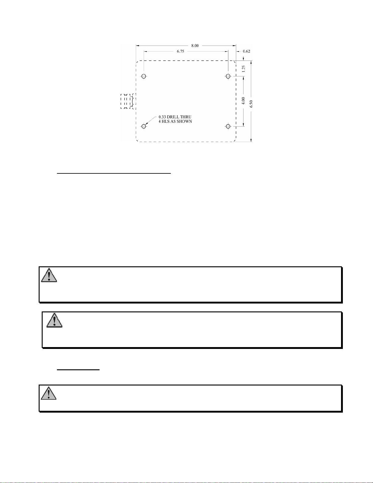
6. 81392001 Auxiliary Battery
a) Mark locations of mounting holes on mounting surface or bracket per Figure 17
b) Drill four (4) 21/64" diameter mounting holes.
c) Open hinged cover of battery enclosure by loosening the four screws. Insert one 5/16-18 UNC
socket head cap screw from the inside of the enclosure through each of the four (4) mounting holes
of the enclosure and into the corresponding holes in the mounting surface or bracket. Assemble
nuts and lock washers to each mounting screw then tighten.
d) The harness has the same wiring configuration as the monitor. See section V.A.2 Monitor
Wiring.
14
Figure 17
Mounting Hole Pattern
B. Communication Address Setup
A RF transmitter controls one 8294-06, 8294-06 EXT and 8394-07 monitors. The transmitter is
digitally encoded with a security code to ensure that it does not accidentally control the wrong
monitor. The receiver has a matching decoder and security code that instantaneously decodes and
interprets commands. The security code is a 15-bit selectable code that is set on both the remote
transmitter and the receiver.
The 8294-06, 8294-06 EXT, and 8394-07 monitors are tested and shipped with a security code based
upon the monitor serial number, ensuring each monitor leaves the factory with a unique code
assigned to it. The security settings will normally not need to be changed. In the case of a lost
transmitter or replaced control board, use the following instructions to change the security settings.
Danger: Using two W.E.T. monitors with the same, security code may cause the
inadvertent control of the wrong monitor, resulting in possible property damage and injury to
personnel. Using the factory specified codes will prevent this problem.
Caution: Do not pinch wires when attaching back panel to front panel of the handheld
enclosure. Ensure all O-ring and gaskets are properly installed when closing receiver or transmitter
enclosures.
C. RF Settings
Caution: The RF Receiver/Control Module and all transmitters’ communication addresses
have been set at the factory. They should not require any additional address settings.

15
1. RF Receiver/Control Module Settings
Remove the cover from the RF receiver/control module. SW4 (Figure 18) allows this board to be
used in different product applications. In order for it to properly operate the Scorpion RF monitor,
it must be set to:
1 8294-06 and 8394-07 Scorpion RF – Blinking Stow Indicator for Dash Panel
Indicator Application
2 8294-06 and 8394-07 Scorpion RF – Non-Blinking Stow Indicator for
Interlock Application
3 8294-06 EXT Scorpion RF
If it is set to a value that is not yet programmed, the status indicator LED, DS5 (Figure 18), will
blink rapidly until a valid setting is selected and power is cycled. If SW4 is set to a valid setting
but not one of the above positions, unpredictable results will occur.
B
A
Status LED
Red
Programmin
g
Button
Figure 18
24263001 Receiver Layout
Caution: Do not change switch A position 1 switch position. This switch is used to set the
priority setting of the transmitter and changing this switch may remove override capabilities.
2. 81282001 Handheld RF Transmitter Settings
a) Remove the battery cover from the handheld RF transmitter. Remove the four screws holding
the two halves of the cover together using a #1 size Pozidriv®screwdriver (use caution with a
standard Phillips screwdriver as it may eventually strip the heads of the screws).
b) Locate the security code switches on the transmitter circuit board (Figure 19).
c) Change the switches to match the settings of the RF Receiver/Control Module except switch
A1. One incorrect setting will prevent the system from working.
SW4

16
d) Ensure the battery lead connector is securely fastened to the transmitter circuit board.
e) Check that no wires will be pinched, close the cover halves and replace the screws. Do not
exceed 6 in-lbs of torque. The screws should just be snug, do not over tighten the screws, or the
plastic enclosure could strip.
Caution: Do not change the switch A position 1 on any transmitter. This switch is used to
set the priority of the transmitter and changing this switch may remove override capabilities.
Caution: While reassembling the handheld remote, ensure both battery and antenna leads
do not become pinched.
Figure 19
Transmitter Security Settings
3. 81327001, 81327011, 81353001 and 81353011 Secondary, Primary, Panel Mount,
and OEM RF Transmitters
a) Disconnect the power connector to the panel-mounted transmitter at the back of the panel.
b) Open the back cover of the transmitter after loosening the screws.
c) Remove the red and black power leads from the power conversion board and place the cover to
the side.
d) Locate the security code switches on the transmitter circuit board (Figure 19).
Other manuals for Scorpion RF 8294-06
1
This manual suits for next models
2
Table of contents
Other ELKHART BRASS Firefighting Equipment manuals


Popular Firefighting Equipment manuals by other brands

Fike
Fike Sita 403-0006 Installation and maintenance instructions

Task Force Tips
Task Force Tips FX100-NN manual

Tyco Fire Suppression & Building Products
Tyco Fire Suppression & Building Products ANSUL AQUASONIC Design, Installation, Recharge, and Maintenance Manual

Tyco
Tyco RAPID RESPONSE RSV-1 manual

Zico
Zico QUIC-STEP HVS-1 Parts and instruction manual

CSW
CSW Smoke Guard 2100 installation manual


