Elliott Roto-Jet I 0620AR Manual

(Supersedes Models 0600, 0600R, 0620, and 0620R)
www.elliott-tool.com
Tube & Pipe Cleaners Tube Testers Tube Plugs Tube Removal Tube Installation
0620A \ 0620AR Roto-Jet I™Cleaning System
Operating and Maintenance Instructions


0620A Roto-Jet I 3
Table Of Contents
Introduction .......................................................................................................... 4
Safety ................................................................................................................... 5
Operation.............................................................................................................. 8
Operating Position (Diagram A)............................................................................ 9
Drive Coupling (Diagram B) ................................................................................ 11
Electrical............................................................................................................. 14
Plug Grounding (Diagram C & D)........................................................................ 15
Schematic (Diagram E)....................................................................................... 17
Maintenance....................................................................................................... 18
Technical Data .................................................................................................... 19
Trouble Shooting Guide...................................................................................... 21
Records ...................................................................................................... 24 & 25
Parts List 0620A ................................................................................................. 26
Parts List 0620AR............................................................................................... 28
Flexshaft Repair ................................................................................................. 30

4 0620A Roto-Jet I
INTRODUCTION
Thank you for purchasing this Elliott product. More than 100 years of experience have been employed
in the design and manufacture of this control, representing the highest standard of quality, value and
durability. Elliott tools have proven themselves in thousands of hours of trouble free eld operation.
If this is your rst Elliott purchase, welcome to our company; our products are our ambassadors. If
this is a repeat purchase, you can rest assured that the same value you have received in the past will
continue with all of your purchases, now and in the future.
The Elliott Roto Jet I™ has been designed for cleaning tubes in the following types of equipment:
Heat Exchangers
Condensers
Chillers
If you have any questions regarding this product, manual or operating instructions, please call Elliott at
+1 800 332 0447 toll free (USA only) or +1 937 253 6133, or fax us at +1 937 253 9189 for immediate
service.

0620A Roto-Jet I 5
SAFETY
Read and save all instructions. Before use, be sure everyone using this machine reads and under-
stands this manual, as well as any labels packaged with or attached to the machine.
1. Know Your Elliott Roto-Jet I™. Read this manual carefully to learn your tool’s applications and
limitations, as well as potential hazards, associated with this type of equipment.
2. Ground Your Elliott Roto-Jet I™. Always use properly grounded electrical outlets, and if using an
extension cord, make sure that it is of the proper size for the electrical load and it is equipped with a
ground wire and ground plug. See “Electrical” section for further information.
3. Avoid Dangerous Environments. Do not use your Elliott machine around or in the presence of
explosive atmospheres (gaseous fumes, dust or ammable materials). Remove materials or debris
that may be ignited by sparks.
4. Keep Work Area Clean and Well Lighted. Cluttered, dark work areas invite accidents.
5. Dress Properly. Do not wear loose clothing or jewelry. Wear a protective hair covering to contain long
hair. It is recommended that the operator wear safety glasses with side shields or a full face shield eye
protection. Gloves and water repellant, nonskid footwear are also recommended. Keep hands and
gloves away from moving parts.
6. Use Safety Equipment. Everyone in the work area should wear safety goggles or glasses with side
shields complying with current safety standards. Wear hearing protection during extended use,
respirator for a conned space and a dust mask for dusty operations. Hard hats, face shields, safety
shoes, respirators, etc. should be used when specied or necessary. Keep a re extinguisher nearby.
7. Keep Bystanders Away. Bystanders should be kept at a safe distance from the work area to avoid
distracting the operator and contacting the exshafting, machine or extension cord. Only the operator
of the machine should engage the foot switch control. NEVER PLACE A WEIGHTED OBJECT ON THE
FOOT SWITCH TO PRODUCE CONTINUOUS OPERATION OF THE MACHINE.
8. Protect Others in the Work Area from debris such as water exhaust and water spray. Provide barriers
or shields as needed.
WARNING
When using electric equipment, always follow basic
safety precautions to reduce the risk of re, electric
shock and personal injury.
WARNING
To reduce the risk of injury, always unplug your machine
before performing any maintenance. Never
disassemble the machine or try to do any wiring
on the electrical system. Contact Elliott for all repairs.

6 0620A Roto-Jet I
SAFETY (CONT.)
9. Use the Right Cleaning Device. Do not use a cleaning device or attachment to do a job for which it
is not recommended. Refer to the Elliott E-100 catalog for all optional equipment. Do not alter the
machine or cleaning device, this will void the warranty on the product.
10. Use Proper Accessories. Use Elliott accessories only. Be sure accessories are properly installed
and maintained. Do not defeat a guard or other safety device when installing an accessory or
attachment.
11. Check for Damaged Parts. Inspect guards and other parts before use. Check for misalignment,
binding of moving parts, improper mounting, broken parts or any other conditions that may affect
operation. If abnormal noise or vibration occurs, turn the machine off immediately and have the
problem corrected before further use. Do not use a damaged machine. Tag damaged machines “Do
Not Use” until repaired. A guard or other damaged part should be properly repaired or replaced by
an Elliott service facility. For all repairs, insist on only identical replacement parts.
12. Remove All Wrenches. Check that all accessory wrenches are removed from the system before
turning it on.
13. Guard Against Electric Shock. Hold the exshaft by the insulated nonmetal casing surfaces. Inspect
and test the Ground Fault Circuit Interrupter (GFCI) prior to each new use of the machine to ensure
its proper operation. For more information refer to the “Electrical” section.
14. Avoid Accidental Starting. Be sure your machine is turned off before plugging it in. Do not use a
machine if the foot switch control does not turn the machine on and off. NEVER USE ANY OBJECT
TO HOLD THE FOOT SWITCH IN THE “ON” POSITION.
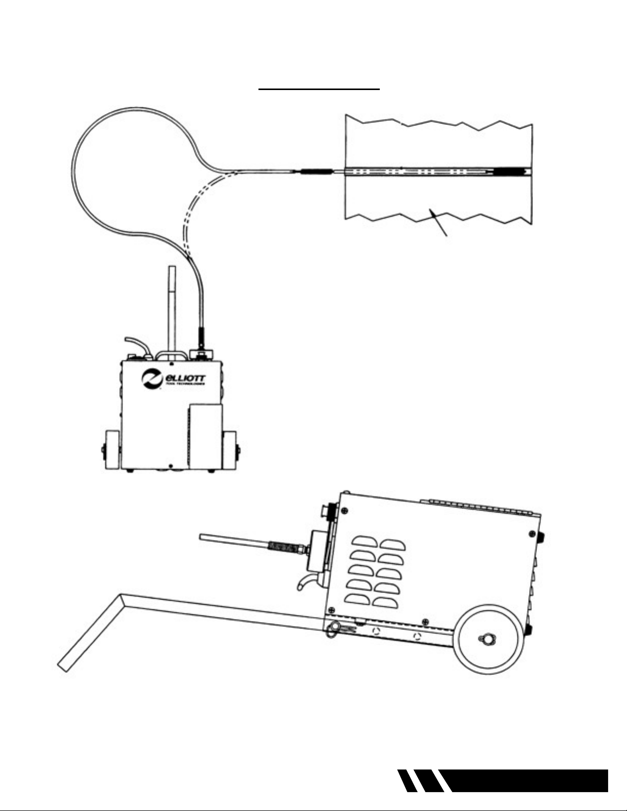
15. Do Not Force the Flexshaft. Your Elliott Roto-Jet™ will perform best at the rate for which it was
designed. Excessive force only causes operator fatigue, increased exshaft wear, shaft or break
away coupling failure.
16. Keep Hands Away from All Moving Parts.
17. Do Not Abuse Cord. Never carry your machine or foot switch by its cord. Never unplug the machine
by yanking the cord from the outlet. Pull the plug rather than the cord to reduce the risk of damage.
Keep the cord away from heat, oil, sharp objects, cutting edges and moving parts.
18. Do Not Overreach - Maintain Control. Keep proper footing and balance at all times.
19. Stay Alert. Watch what you are doing, and use common sense. DO NOT use a machine when you
are tired, distracted or under the inuence of drugs, alcohol or any medication causing decreased
control.
20. Unplug Machine when it is not in use, before changing accessories or performing recommended
maintenance.
21. Maintain Machine Carefully. Keep handles dry, clean and free from oil and grease. Follow
instructions for lubricating and changing accessories. For more information see “Maintenance”
section. Periodically inspect the machine cord and extension cords for damage. Have damaged
parts repaired or replaced by an Elliott service facility.
22. Store Idle Machines. When not is use, store your machine in a dry, heated, secured place. For more
information see “Maintenance” section.

0620A Roto-Jet I 7
Wet Shafts (Fig.1)
Prex Part Number Casing Outside Diameter Tube Inside Diameter
inch mm inch mm
0511*(xx) .250 6 5/16 - 3/8 8 - 10
0512*(xx) .375 10 7/16 - 1/2 11 - 13
0513*(xx) .500 13 9/16 - 1 14 - 25
0514A*(xx) .625 16 3/4 - 1-1/2 19 - 38
0514*(xx) .750 19 1 - 2 25 - 50
0515*(xx) 1.000 25 2 and over 50 and over
*Length of shaft in feet completes the part number.
(Available in standard lengths of 16’, 25’, 33’, and 49’. Consult factory for additional lengths.)
Dry Shafts (Fig.2)
Prex Part Number Casing Outside Diameter Tube Inside Diameter
inch mm inch mm
0534*(xx) 7/8 22 1 and over 25 and over
*Length of shaft in feet completes the part number.
(Available in standard lengths of 25’, 35’, and 50’. Consult factory for additional lengths.)
SAFETY (CONT.)
23. Maintain Labels and Nameplates. These carry important information and will assist you in ordering
spare and replacement parts. If unreadable or missing, contact an Elliott service facility for a
replacement.
24. Stop the Machine Immediately if the Flexshaft Starts to Coil. Flexshaft damage will occur if exshaft is
operated in a coiled position.
25. Use the Proper Flexshaft to t the tubes to be cleaned. Never use a exshaft that is too small or too
short. Flexshaft failure will result if too great a resistance is placed on the exshaft. Refer to the chart
below for sizing information. (See Fig. 1 and 2)

8 0620A Roto-Jet I
OPERATION
Correct Machine Position and Operation is critical to getting the job done quickly and efciently.
This can be accomplished by the following these steps:
Examine the tubes to be cleaned and measure the internal diameter (Elliott Tube Gage is
recommended) and length of the tubes. If the tube ends are expanded, then make a note of the
smallest internal diameter. Record these measurements on the charts provided on page 22 and 23
of this manual. You will need these measurements to select the proper size exshaft and cleaning
attachments.
Roll or hand carry the machine to the location where the cleaning will take place.
Position the machine at a right angle to the tube sheet or cleaning area. This will keep the exshaft
at the proper radius. NEVER OPERATE THE MACHINE IN THE VERTICAL POSITION. (See Diagram
A page 7).
Remove pin from handle bracket and lower handle on the machine to its lowest setting and replace
the handle pin.
Lower the machine to the horizontal position, resting the end of the handle on the oor.
Open the foot switch storage compartment and remove the foot switch, “O” ring, and rubber hose
washer.
Position lug on foot pedal plug to line-up with slot in plug receptacle and push plug in place. Then
thread the outer ring of the foot pedal plug onto the plug receptacle until tight. The foot switch can
only be connected in one position.
Place the rubber hose washer in the water hose connection of the machine. This is a one time
operation. The rubber washer can remain in this connection and does not require removal after use.
Connect a standard garden hose to the 3/4” water hose connection of the machine. The machine
is designed for “Municipal” water pressure only, Max 100 psi (6.89 Bar-Metric). DO NOT connect
the water connection to a “High Pressure” source. Water is important to the cleaning process as it
ushes away deposits cleaned from the tube and helps to lubricate and cool the exshaft.
Position the “O” ring in the recess of the exshaft connection manifold.
TOOL TIP
Always select a smaller size of cleaning device for heavy
tube deposits. With the exception of the Elliott Turbo Brush,
never use a brush or cleaning device larger than the internal
diameter of the tubes.

0620A Roto-Jet I 9
DIAGRAM A
Tube Bundle
Roto-Jet I
TOP VIEW
CORRECT OPERATING POSITION

10 0620A Roto-Jet I
OPERATION (CONT.)
Prepare the exshaft by loosening the four (4) set screws located in the brass locking sleeve using
a 3/32” Allen wrench. Thread the breakaway or solid square drive into the coupling adapter that
is swaged on the core of the exshaft. Position the brass locking sleeve equally over the coupling
adapter and the breakaway or solid square drive. Firmly tighten the four (4) Allen set screws. (See
Diagram B page 9)
Insert the square drive into the manifold of the machine. Rotate the exshaft by hand to properly seat
the square drive of the exshaft into the manifold. Thread the brass manifold cap onto the manifold of
the machine and rmly hand tighten.
Attach the chosen cleaning device to the tool coupling swaged to the core of the exshaft at the
opposite end from the manifold connection and rmly tighten the device.
Plug the machine into the appropriate electrical source. For more information see “Electrical” section.
Turn on the water supply.
Layout the exshaft as straight as possible. DO NOT start the machine with the exshaft in a coiled
position.
Depress the foot switch. The electric motor will operate and drive the exshaft, which will rotate
the cleaning device. At the same time, water will pass through the machine and out the end of the
exshaft casing near the cleaning device. Remove your foot from the foot switch and both the water
and rotation of the shaft will stop. Restart the machine and observe the water output from the end of
the exshaft casing. A constant stream of water should be discharged from the casing as the core
rotates. If no water is discharged from the exshaft, check the hose and hose connection for any
“kinks” that would restrict water ow. If there is no rotation of the exshaft, check the Ground Fault
Circuit Interrupter (GFCI) reset button. For more information see “Electrical” section. Depress the foot
switch again and observe the water ow from the end of the exshaft. If no water is discharged, from
the exshafting, discontinue use of the machine and contact an Elliott service facility.
For model 0620AR, let machine completely stop rotation before depressing the reversing peddle.
Reverse rotation and water ow will begin when the reverse peddle is depressed and will stop when
released.
TOOL TIP
For model 0620AR machines, to prevent the cleaning device from unthreading
when using the reverse mode of the machine, place a 1/4” lock washer
between the tool coupling and the cleaning device and rmly tighten the
connection.

0620A Roto-Jet I 11
DIAGRAM B
Manifold Cap
Brass Locking
Sleeve Optional Drive Couplings
Break-Away Coupling
Solid Coupling
Coupling Adapter

12 0620A Roto-Jet I
OPERATION (CONT.)
The machine is now ready to operate.
Hold the end of the exshaft with your hand about 12” (304.8mm) back from the cleaning device.
Insert the cleaning device just inside the tube to be cleaned and hold the exshaft away from your
body. Depress the foot switch and start to feed the exshaft down the tube.
It is important that the exshaft not be forced down the tube. If you meet resistance, proceed at a
slower pace or ret the exshaft with a smaller cleaning device. Should the exshaft meet too much
resistance it will begin to coil. DO NOT ALLOW THE FLEXSHAFT TO COIL. Coiling of the exshaft
could cause binding within the casing and shear the core material. If a blockage is encountered, and
the shafting begins to coil, immediately stop feeding the shafting into the tube and start drawing the
shafting back until coiling stops. Then proceed to slowly feed the exshafting into the tube, being sure
to draw the shafting back when blockage is encountered and coiling begins. Follow this procedure
until the cleaning device removes the blockage.
TOOL TIP
Operate the exshaft as straight as possible to minimize any sharp radius
bends. This applies to both brush insertion and maximum cleaning length.
Operating the exshaft in a constant sharp radius will ex fatigue the wires in
the core reducing its strength. Allowing the cleaning device to exit the tube
while rotating can cause premature shaft failure in the tool coupling area.
Never exit the tube with the tube cleaning device in operation. For more
information see “Technical” section.
WARNING
This machine drives high speed, rotating cleaning devices. It is recommended
that the operator wear safety glasses with side shields or full face shield eye
protection, gloves and water repellant, nonskid foot wear. Avoid contact with
objects other than the tube when the machine is in operation.
TOOL TIP
Measure the length of the tubes being cleaned from the tube sheet to the tube
sheet at the opposite end. Transfer this measurement to the exshaft from
the END of the cleaning device up the casing toward the machine. Mark the
end of the measurement on the casing by wrapping the point with electrical
tape. This will enable you to feed the exshaft through the tube and stop
the cleaning device before exiting the tube on the opposite end. For Model
0620AR users, stop forward rotation of the machine when the tape mark
reaches the tube sheet and start reverse rotation to back the cleaning device
out of the tube.

0620A Roto-Jet I 13
OPERATION (CONT.)
After cleaning has been completed, unplug the machine from the electrical source.
Remove the foot switch by unthreading the outer ring of the foot switch plug and pull the plug from its
receptacle.
Return the foot switch to the storage compartment.
Remove the exshaft by rotating the manifold cap counter-clockwise from the manifold then pull the
exshaft free from the drive coupling.
Drain any excess water from the exshaft.
Remove the “O” ring from the manifold and place it in the plastic bag and return the bag to the storage
compartment and close the door.
Remove the water hose from the machine.
Return the machine to the upright position.
For handle and axle assembly removal from the machine; remove the two hex head cap screws from
the axle with a 7/16” wrench or socket and remove the axle assembly.
Remove the two hex head cap screws from the handle assembly using a 7/16” wrench or socket and
remove handle assembly.
To replace handle and axle assemblies, reverse the order for disassembly. Note that the axle cut out is
positioned over the handle assembly tab.
TOOL TIP
Start to clean the tube bundle from the top of the unit to the bottom. Clean
the bundle one row at a time, marking with soapstone, each row of tubes that
have been cleaned.

14 0620A Roto-Jet I
ELECTRICAL
Your Elliott Roto-Jet I™ has been designed to require a grounded electrical receptacle, of 120 volts,
single phase, 20 amps, A.C. current. Serious damage to the unit can occur within the electrical
components if the electrical supply, voltage and amperage rating does not meet this requirement. An
electrical diagram is supplied with this manual as a reference (page 15). Only a qualied electrician
should use the electrical diagram to perform any maintenance or repairs.
This machine requires electrical grounding. A three prong grounding plug must be used with this
machine. The plug must be connected to a properly grounded outlet (see Diagram C). If the machine
should electrically malfunction or breakdown, grounding provides a low resistance path to carry
electricity away from the user, reducing the risk of electrical shock.
The grounding prong in the plug is connected through the green wire inside the cord to the grounding
system in the machine. The green wire in the cord must be the only wire connected to the tool’s
grounding system and must never be attached to an electrically “live” terminal.
Your machine must be plugged into an appropriate outlet, properly installed and grounded in
accordance with all codes and ordinances. A temporary adapter may be used for connecting
grounded plugs to two prong outlets. The green rigid ear or lug extending from the adapter must
be connected to a permanent ground such as a properly grounded outlet box or receptacle. Simply
remove the center screw from the outlet, insert the adapter and reattach the screw through the
green grounding ear to the outlet. If in doubt of proper grounding, contact a qualied electrician. A
temporary adapter should only be used until a properly grounded outlet can be installed by a qualied
electrician. (See Diagram D) The Canadian Electrical Code prohibits the use of temporary adapters.
WARNING
Improperly connecting the grounding wire can result in the risk of electric
shock. Check with a qualied electrician if you are in doubt as to whether
the outlet is properly grounded. DO NOT modify the plug provided with the
machine. Never remove the grounding prong from the plug. DO NOT use the
machine if the cord or plug is damaged. If damaged, have it repaired by an
Elliott service facility before use. If the plug will not t the outlet, have a proper
outlet installed by a qualied electrician.

0620A Roto-Jet I 15
ELECTRICAL (CONT.)
Extension cords may be used with the machine, providing the cord is equipped with three wires,
12 gauge in size, with ground plugs and not longer than 50’ in length. Using extension cords with
inadequately sized wire causes a serious drop in voltage resulting in possible machine damage. The
smaller the gauge number of the wire, the greater the capacity of the cord. For example, a 12 gauge
cord can carry a higher current than a 14 gauge cord.
• If you are using an extension cord outdoors, be sure it is marked with the sufx “W-A” (“W” in
Canada) to indicate that it is acceptable for outdoor use.
• Be sure your extension cord is properly wired and in good electrical condition. Always replace
a damaged extension cord or have it repaired by a qualied person before using it.
• Protect your extension cords from sharp objects and excessive heat.
DIAGRAM C
DIAGRAM D
Grounding Prong
Cover of Grounded
Outlet Box
Outlet Ground
Screw
Green Grounding Ear
Cover of Grounded
Outlet Box
Temporary
Adapter

16 0620A Roto-Jet I
ELECTRICAL (CONT.)
Ground Fault Circuit Interrupter (GFCI). Your Elliott Roto-Jet I™ is equipped with a Ground Fault
Circuit Interrupter located under the rain tight electrical cover. This receptacle provides added
protection in reducing the risk of electric shock. You should “test” the GFCI receptacle prior to each
new operating use. Testing of the GFCI receptacle is as follows:
• Plug machine into proper electrical outlet.
• Lift cover of rain tight mount receptacle cover.
• Locate and push the “test” button, with your nger, in the center of the Ground Fault Circuit
Interrupter. Never use any other device to push the test button.
• An audible “click” should be heard when the button is depressed.
• Engage the foot switch of the machine. The machine Should Not operate.
• Release the foot switch of the machine, locate and push the “reset” button, with your nger.
• Engage the foot switch of the machine. The machine should operate normally.
If the machine should fail this testing process, contact an Elliott service facility immediately. Do Not
attempt to use the machine in this condition. An electric shock could occur if there is a malfunction
of the GFCI circuit.
The electrical outlet portion of the GFCI has been provided to enable the operator to plug in auxiliary
electrical devices, such as a work light, etc. The maximum amperage rating of the GFCI outlet is 15
amps. No device should be used in this outlet with a higher amperage requirement. Exceeding the
maximum amperage rating of this outlet could result in machine damage.

0620A Roto-Jet I 17
DIAGRAM E

18 0620A Roto-Jet I
MAINTENANCE
Keep your Roto-Jet I™ in good repair by adopting a regular maintenance program. Before each
use, examine the general condition of your machine. Inspect connections, foot switch, machine
cord set and extension cords for damage. Check for loose screws, misalignment, binding of moving
parts, improper mounting, split exshaft casing, broken parts or any other condition that may affect
its safe operation. If abnormal noise or vibration occurs, turn the machine off immediately and have
the problem corrected before further use. For more information see “Trouble Shooting” section. DO
NOT USE A DAMAGED MACHINE. Tag damaged machines “DO NOT USE” until repaired.
Under normal conditions lubrication of the machine between uses is not necessary, unless the ma-
chine has been operated “dry”. Should you wish to use the machine dry, the manifold drive shaft
must be lubricated with a few drops of oil. Position the machine vertically, use a standard long spout
oil can to place the oil behind the brass square drive coupling. Using the machine dry after it has
been used for wet operation, could damage the seals and bearings, which may require replacement
if not lubricated..
Clean dust and debris from vents. Keep the machine handles clean, dry and free of oil or grease.
Your machine has been nished with a two-part, epoxy, paint coating that is very durable and should
last the life of the machine. Use only mild soap and a damp cloth to clean your machine. Certain
cleaning solvents may be harmful to the painted surfaces. Never use ammable or combustible
solvents around machines.
After each use, drain all water from the exshaft outer casing. Store the exshaft by laying it down,
in a large diameter coil, in a dry, secured area.
After every cleaning season or 12 months remove the machine cover and check the “V” belt for
cracking and wear. Replace the cover and position the machine vertically. Lubricate the mani-
fold drive shaft, behind the female brass square drive coupling with a few drops of oil. An oil can
with a standard long spout will be required. Make sure the exshaft casing is drained of all water.
Lubricate the exshaft with a water soluble lubricant solution diluted to the manufacturers recom-
mendations. An oil can with a standard long spout will be required. Position the spout between the
exshaft core and the casing. Fill and drain the exshaft from both ends. When nished, store the
exshaft by laying it down, in a large diameter coil, in a dry, secured area. Start the next cleaning
season by operating the machine prior to starting a new job. For more information on proper opera-
tion see “Operation” section.
WARNING
To reduce the risk of injury, always unplug your machine before performing
any maintenance. Never disassemble the machine or try to do any rewiring
on the machine’s electrical system. Contact Elliott for all repairs.

0620A Roto-Jet I 19
TECHNICAL DATA
Horsepower: 1 H. P. Electric Motor
Voltage: 115 Volts, Single Phase, 60 Cycles, 12.5 Amps.
G. F. C. I. Trip Threshold: 5 mA
G. F. C. I. Trip Time: 0.025 Seconds Nom. Per UL Std.
Wheel Size: 8” (203.2 mm) Outside Diameter x 2.250” (57.15 mm) Hub Width
x .750” (19.05 mm) Inside Diameter
Overall Size Without Hand Cart: 17” x 15” x 10.5” (431.8 x 381 x 266.7 mm)
Overall Hand Cart Size: 21.5” x 34” x 6” (546.1 x 863.6 x 152.4 mm) Handle Retracted
41” (1041.4 mm) Handle Extended
Unit Weight Without Cart: 67 lbs. (30.39 kg)
Unit Weight With Cart: 72 lbs. (32.66 kg)
The charts below refer to the exshafts only. Match the prex numbers to your shafting size. (See
Fig. 3 and 4)
Wet Shafts (Fig.3)
Prex Flexshaft Number Maximum Torque
(Inch Pounds) (Newton-Meters)
0511*(xx) 16 1.8
0512*(xx) 105 11.9
0513*(xx) 210 23.7
0514A*(xx) 295 33.3
0514*(xx) 580 65.5
0515*(xx) 1155 130.5
Dry Shafts (Fig.4)
Prex Flexshaft Number Maximum Torque
(Inch Pounds) (Newton-Meters)
0534*(xx) 580 65.5
*Length of shaft in feet completes the part number.
(Available in standard lengths of 16’, 25’, 33’, and 49’. Consult factory for additional lengths.)
*Length of shaft in feet completes the part number.
(Available in standard lengths of 25’, 35’, and 50’. Consult factory for additional lengths.)
Maximum Torque Ratings For Flexshaft Core Material When Lying Straight

20 0620A Roto-Jet I
Wet Shafts (Fig.5)
Flexshaft
Prex No.
Radius 4” Radius 6” Radius 8” Radius 10” Radius 12” Radius 15” Radius 20” Radius 25”
0511*(xx) 2 3 3 4 4 4 4 4
0512*(xx) 11 14 17 20 22 23 25 26
0513*(xx) 21 25 34 39 42 45 48 52
0514A*(xx) 25 36 47 55 57 59 68 74
0514*(xx) N/A 53 74 95 107 119 131 140
0515*(xx) N/A N/A 105 139 168 200 221 242
When the exshaft is used in a bend or radius conguration, the maximum torque capability of the
core is reduced. The following charts demonstrate the effect that bending has on the exshaft.
(See Fig. 5, 6, 7, and 8)
Above gures represent Inch Pounds of Torque to Flexshaft Fatigue.
Wet Shafts (Fig.6)
Flexshaft
Prex No.
Radius
102mm
Radius
152mm
Radius
203mm
Radius
254mm
Radius
305mm
Radius
381mm
Radius
508mm
Radius
635mm
0511*(xx) 0.2 0.3 0.3 0.5 0.5 0.5 0.5 0.5
0512*(xx) 1.2 1.6 1.9 2.3 2.5 2.6 2.8 2.9
0513*(xx) 2.4 2.8 3.8 4.4 4.7 5.1 5.4 5.9
0514A*(xx) 2.8 4.1 5.3 6.2 6.4 6.7 7.7 8.4
0514*(xx) N/A 6.0 8.4 10.7 12.1 13.4 14.8 15.8
0515*(xx) N/A N/A 11.9 15.7 19.0 22.6 25.0 27.3
Above gures represent Newton-Meters of Torque to Flexshaft Fatigue.
*Length of shaft in feet completes the part number.
(Available in standard lengths of 16’, 25’, 33’, and 49’. Consult factory for additional lengths.)
Dry Shafts (Fig.7)
Flexshaft
Prex No.
Radius 4” Radius 6” Radius 8” Radius 10” Radius 12” Radius 15” Radius 20” Radius 25”
0534*(xx) N/A N/A N/A 95 107 119 131 140
Above gures represent Inch Pounds of Torque to Flexshaft Fatigue.
Dry Shafts (Fig.8)
Flexshaft
Prex No.
Radius
102mm
Radius
152mm
Radius
203mm
Radius
254mm
Radius
305mm
Radius
381mm
Radius
508mm
Radius
635mm
0534*(xx) N/A N/A N/A 10.7 12.1 13.4 14.8 15.8
Above gures represent Newton-Meters of Torque to Flexshaft Fatigue.
*Length of shaft in feet completes the part number.
(Available in standard lengths of 25’, 35’, and 50’. Consult factory for additional lengths.)
This manual suits for next models
1
Table of contents
Other Elliott Other manuals