manuals.online logo
Brands
  1. Home
  2. •
  3. Brands
  4. •
  5. Bacharach
  6. •
  7. Other
  8. •
  9. Bacharach MGS 550 User manual

Bacharach MGS 550 User manual

The Bacharach MGS-550 is an instrument for the continuous
monitoring of toxic and combustible gases, oxygen and
refrigerants in ambient air. The instrument is housed in a rugged
ABS or aluminum enclosure for indoor and outdoor applications.
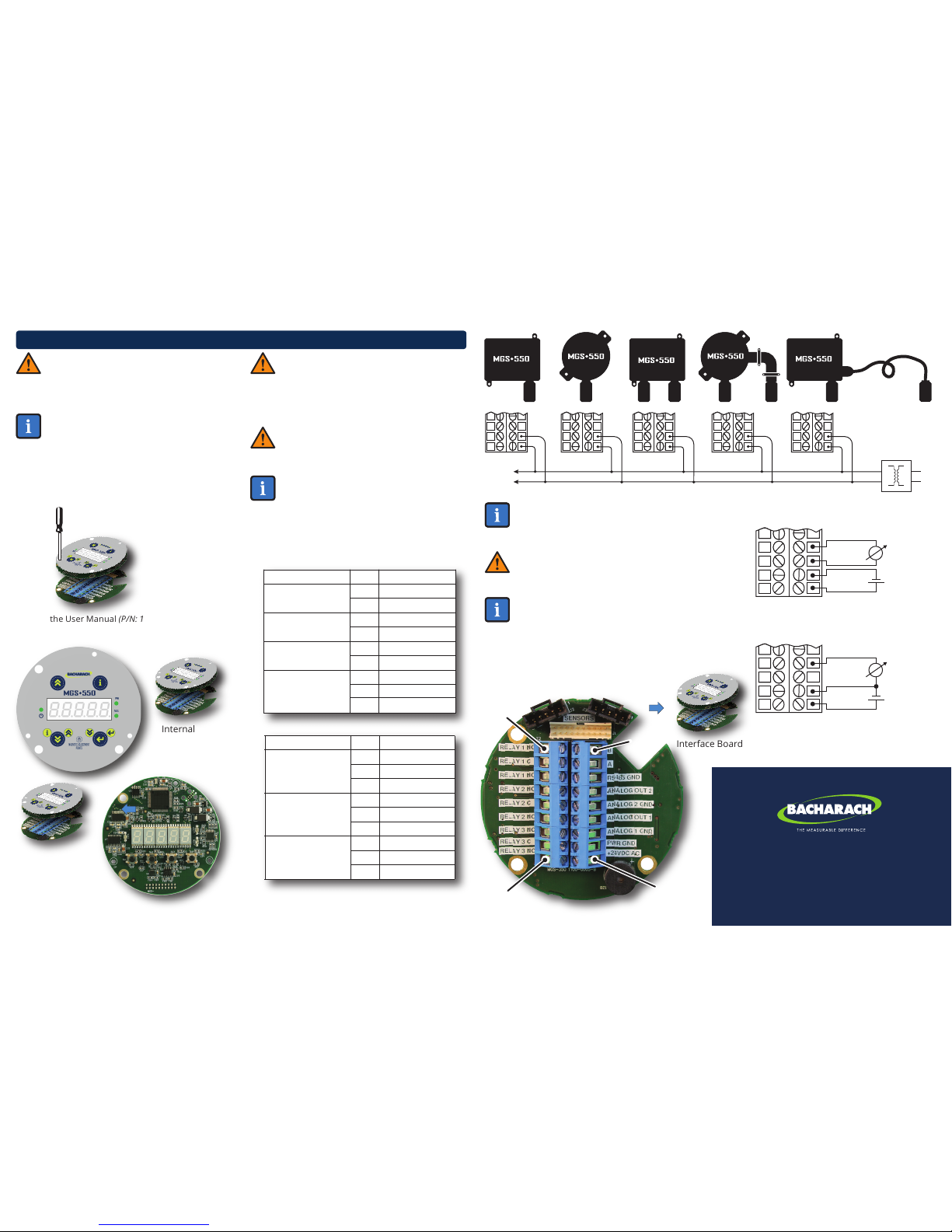
The instrument can be connected to a Bacharach monitoring
system or a Programmable Logic Controller (PLC). With the
integrated alarm relay configuration, the instrument can be
operated as a stand-alone unit (with additional local alarm
signaling). The instrument is designed to be installed in
non-classified, non-hazardous, permanent locations.
The instrument is powered by 19.5 to 28.5 VDC or 24 VAC (± 20%).
The measured gas concentration is converted to a 4 to 20 mA, 0 to
5 V, 0 to 10 V, 1 to 5 V, 2 to 10 V analog and digital Modbus RTU
output signal. The instrument accepts wire sizes of 16 to 24 AWG
(0.2 to 1.5 mm2).
USER MANUAL: Before using this equipment, carefully read
and strictly follow the MGS-550 User Manual (P/N: 1100-1000).
The user must fully understand and strictly observe the
instructions. Use the equipment only for the purposes listed
and under the conditions specified in that document.
CODE COMPLIANCE: Comply with all local and national laws,
rules and regulations associated with this equipment.
GENUINE PARTS: Use only genuine Bacharach spare parts
and accessories, otherwise proper functioning of the
equipment may be impaired.
FLAME PROOF AND EXPLOSION PROOF JOINTS: Joints of the
flame proof/explosion proof enclosure are not in accordance
with the relevant minimum or maximum values of EN/IEC
60079-1. The joints are not intended to be re-worked by the user.
EXPLOSIVE DIRECTIVES: As long as no EC-Type Examination
Certificate per Annex II, clauses 1.5.5, 1.5.6 and 1.5.7 of
Directive 94/9/EC exists: the measuring function of the gas
detection transmitter for explosion protection, according to
Annex II, clauses 1.5.5, 1.5.6 and 1.5.7 of Directive 94/9/EC is
not covered.
When using the product in areas subject to explosion hazards,
refer to the following:
● Instruments or components for use in explosion-hazard
areas which have been tested and approved according to
national, European or international Explosion Protection
Regulations may only be used under the conditions
specified in the approval and with consideration of the
relevant legal regulations.
● The instruments or components may not be modified in any
manner. The use of faulty or incomplete parts is
forbidden. The appropriate regulations must be
observed at all times when carrying out repairs on these
instruments or components.
FULL-SIZE
MOUNTING
TEMPLATES --
DO NOT
RESCALE
115.0 mm (4.53 in)
120.6 mm (4.75 in)
Mounting
Point (ABS)
144.1 mm (5.67 in)
COMPONENT WIDTH HEIGHT DEPTH
mm in mm in mm in
General Purpose Enclosure
Rugged Enclosure
210
125
8.3
4.9
225
190
8.9
7.5
85
90
3.4
3.5
kg lbs
1
1.6
2
3.5
WEIGHT
CAUTION: DO NOT USE this product in
oxygen-enriched environments of >21% oxygen.
High “off-scale” readings may indicate an explosive
concentration.
WARNING: Strictly follow the instructions in the User
Manual (P/N: 1100-1000).
1. Operating Area & Conditions
ENVIRONMENTAL CONSIDERATIONS: Carefully consider the full
range of environmental conditions to which the instruments will
be exposed.
TARGET GAS CONSIDERATIONS: The physical data of the gas or
vapor to be detected must be observed.
APPLICATION CONSIDERATIONS: The specifics of the
application (for example, possible leaks, air movement/draft, etc.)
must be observed.
ACCESSIBILITY CONSIDERATIONS: The degree of accessibility
required for maintenance purposes must be granted.
ACCESSORY CONSIDERATIONS: The types of optional and
accessory equipment that will be used with the system must be
kept in mind.
SENSOR POSITIONING: When installing the instrument or the
remote sensor, the sensor opening should always be pointing
downward.
SUN SHIELD CONSIDERATIONS: If the instrument is exposed to
direct sunlight, the use of a sun-shield is recommended.
3. Mounting
4. Weight & Dimensions (Approximate)
2. Safety Instructions
Refrigerant Gas Detector
for Machinery Rooms, Cold Rooms & Freezers
Refrigerant Leak Detection
P/N: 1100-0999 | November 2018 Revision 1
Quick Start
Guide
For more detailed product information, scan here or visit
http://bit.ly/2DozhbY to access the MGS-500 User
Manual (P/N: 1100-1000).
This quick start guide has been translated into the
following languages: Deutsch, Español, Français, Italiano
and Nederlands. To download a translated document,
scan here or visit http://bit.ly/2DozhbY.
Languages
1: Strip 0.2 to 0.25 inches (5 to 7 mm) of wiring insulation.
2: Connect the wires as indicated.
RELAY 1 NC
RELAY 1 C
RELAY 1 NO
RELAY 2 NC
RELAY 2 C
RELAY 2 NO
RELAY 3 NC
RELAY 3 C
RELAY 3 NO
10
11
12
13
14
15
16
17
18
Relay 1 Output
Relay 2 Output
Relay 3 Output
FUNCTION PIN LABEL
M20 OPENINGS: The ABS and the flame proof /
explosion proof enclosures provide four M20 openings
for cable glands or plugs. These openings can be used
for field wiring, direct attachment of a sensor or wiring
of a remote sensor. Unused openings must be closed
with a suitable plug and gasket, maintaining the IP or
Ex d rating.
PIN 10
PIN 18
PIN 9
PIN 1
Connector Style
May Vary Slightly
from Photo
NOTE: For 24 VDC installations, the input is protected.
If the polarity is reversed, the instrument will not
power-up.
NOTE: To make wiring connections, you must first
open the MGS-550 housing. The enclosure lid of
the IP66 ABS housing has four captive screws. The
enclosure lid of the Ex d (flame proof/explosion
proof) housing unscrews.
Next, carefully disconnect the combination Display
Bezel and Processor Board (which remain connected)
from the lower Interface Board by unscrewing the 3
captive screws. Access the captive screws through
holes in the Display Bezel.
Internal
Display Bezel
(Top Layer)
Processor
Board
(Middle Layer)
with Keyed
Ribbon Cable
Interface Board
(Bottom Layer)
PWR
GND
24VAC
PWR GND
24VAC
AC
POWER
PWR
GND
24VAC
PWR
GND
24VAC
PWR
GND
24VAC
PWR
GND
24VAC
PWR GND
24VAC
SUPPLY
TRANSFORMER
4-Wire Power and Output to
Central Control System
3-Wire Power and Output to
Central Control System
mA
A OUT 1
A1 GND
PWR GND
+24VDC
-
+
mA
A OUT 1
PWR GND
+24VDC
-
+
Refer to the User Manual (P/N: 1100-1000) for detailed
instructions on accessing the internal components
for wiring.
+24VDC/AC
PWR GND
ANALOG 1 GND
ANALOG OUT 1
ANALOG 2 GND
ANALOG OUT 2
RS-485 GND
A
B
1
2
3
4
5
6
7
8
9
Power
(+24VDC or 24VAC)
Analog Output 1
Analog Output 2
Modbus RTU
FUNCTION PIN LABEL
USA Customer Service: +1 724 334 5000
CAN Customer Service: +1 905 882 8985
EU Customer Service: +353 1 284 6388
website: mybacharach.com |email: help@mybacharach.com
Copyright © 2018 Bacharach, Inc. All Rights Reserved
SHIELD WIRE WARNING: Connect the shield of the
power wires to the earth ground of the central control
system (e.g., chassis, ground bus bar, etc.).
WARNING: The MGS-550 must be powered by either
(a) a suitable UL 60950/CSA certified power supply that
is isolated from line voltage by double insulation, or (b)
an appropriately rated UL listed/CSA Class 2
transformer. Failure to comply can result in personal
injury or death.
NOTE: For connections to an external controller such
as a Bacharach MGS or GDA, refer to the manual that
was included with the controller.
NOTE: After wiring is completed, carefully
re-assemble the enclosure and its components,
noting the keyed ribbon cable and sensor
connectors. After installation is complete, be sure
to refer to the User Manual (P/N: 1100-1000) for
detailed instructions on registering the sensors and
configuring the MGS-550 for proper operation.
POLARITY WARNING: For 24 VAC installations in a
daisy-chain configuration, the neutral polarity must be
maintained for all instruments.
5. Wiring

Other manuals for MGS 550

5

Other Bacharach Other manuals

Bacharach MVR-300 UK User manual

Bacharach

Bacharach MVR-300 UK User manual

Bacharach Model 105 Manual

Bacharach

Bacharach Model 105 Manual

Bacharach MGS-150 User manual

Bacharach

Bacharach MGS-150 User manual

Popular Other manuals by other brands

OTIS GEN II OI-6000 Operation manual

OTIS

OTIS GEN II OI-6000 Operation manual

Autel AutoLink EBT 210 manual

Autel

Autel AutoLink EBT 210 manual

Siemens MDS D423 operating instructions

Siemens

Siemens MDS D423 operating instructions

Nokia 6360 user guide

Nokia

Nokia 6360 user guide

Bazzaz T143 installation instructions

Bazzaz

Bazzaz T143 installation instructions

LAMBORGHINI PAC 120 - SCHEMA manual

LAMBORGHINI

LAMBORGHINI PAC 120 - SCHEMA manual

Clarke CAR8MC user guide

Clarke

Clarke CAR8MC user guide

Haldex KN18530 Series installation instructions

Haldex

Haldex KN18530 Series installation instructions

Feig Electronic OBID Classic-Pro ID CPR.M02 Series installation manual

Feig Electronic

Feig Electronic OBID Classic-Pro ID CPR.M02 Series installation manual

NexSens X2 manual

NexSens

NexSens X2 manual

Guidosimplex D932 user guide

Guidosimplex

Guidosimplex D932 user guide

LAMBORGHINI LED 24 MB W TOP - SCHEMA manual

LAMBORGHINI

LAMBORGHINI LED 24 MB W TOP - SCHEMA manual

Honeywell RM7895A1014 installation instructions

Honeywell

Honeywell RM7895A1014 installation instructions

Haldex PURest RN60AB installation guide

Haldex

Haldex PURest RN60AB installation guide

EMAC SoM-210FS user manual

EMAC

EMAC SoM-210FS user manual

Painless Performance Products 10106 installation instructions

Painless Performance Products

Painless Performance Products 10106 installation instructions

Sven OVP-15P user manual

Sven

Sven OVP-15P user manual

Fidelity Electronics SP-POS88IV SERIES Operation manual

Fidelity Electronics

Fidelity Electronics SP-POS88IV SERIES Operation manual

manuals.online logo
manuals.online logoBrands
  • About & Mission
  • Contact us
  • Privacy Policy
  • Terms and Conditions

Copyright 2025 Manuals.Online. All Rights Reserved.