ElliptiGO MSUB User manual

ELECTRIC BIKE CONVERSION KIT MANUAL
MSUB/RSUB

Thank you for purchasing an electric bike conversion kit for your ElliptiGO bike. We have spent many
hours developing and testing different electric bike solutions and we believe this kit is going to give you
a fantastic riding experience. We hope you enjoy many years of healthy exercise and fun while using it.
As fun as an electrified ElliptiGO can be to ride, we want to emphasize that your ElliptiGO bike is not a
toy. It is an advanced piece of fitness equipment designed to be used for exercise by responsible riders.
This electric bike conversion kit is designed so that you can install it at home. However, it is critical that
you follow the directions. Your safety is our primary concern. An electrical device like this with a
powerful motor mounted onto a bicycle can result in significant injuries if not installed properly. Please
review this owner’s manual and watch the recommended videos before beginning the installation. Then
follow the instructions carefully. If you need assistance with the installation, please don’t hesitate to
contact us at service@elliptigo.com. We are here to make your experience as positive as possible. For
the most up to date version of the manual and installation procedures, please visit
www.elliptigo.com/manuals.
If you have any questions or concerns about any of your ElliptiGO products, please contact us at
service@elliptigo.com.
Happy Riding,
Brent and Bryan
ElliptiGO Co-Founders

IMPORTANT NOTIFICATIONS
DO NOT SKIP THIS SECTION!
Like all forms of cycling, riding an ElliptiGO® bike involves a
real risk of serious injury, maiming and death. Each time you
ride your ElliptiGO bike you are assuming this risk. We cannot
stress enough how important it is to wear a helmet and proper
clothing, know and follow the rules of the road, ensure your
bike is in good working order before and during your ride, and
to use caution when riding.
To help minimize your risk of injury when riding your bike with
an electric bike kit installed, it is critical that you read and
understand the contents of this manual and become familiar
with operating and maintaining your bike before you head out
on the road.
No manual can address all of the potentially hazardous
situations that could arise when riding a bike. As a result, we
cannot provide guidance on how to be safe in every
circumstance. There are many unpredictable and unavoidable
risks that are inherent in the sport of cycling. By choosing to
ride a bike, you are voluntarily exposing yourself to these risks
and are responsible for that choice. The magnitude of these
risks tends to increase as your speed increases, so by
choosing to ride a motorized bike, you are exposing yourself
to a higher likelihood of serious injury, maiming and death.
To highlight some of the most important safety concerns, this
manual includes many “Warnings”, “Cautions” and “Alerts.”
They are set out conspicuously in the manual.
Safety Warning
The following symbol:
WARNING!
(the safety designator
together with the word WARNING!), calls attention to a
potential hazard that, if not properly addressed or avoided,
could cause serious injury or death.
Safety Caution
The following symbol:
CAUTION!
(the safety designator
together with the word CAUTION!), calls attention to a
potential hazard that, if not properly addressed or avoided,
could cause property damage or an injury.
Damage Alert
The designation
ALERT!
calls attention to a situation which, if
not properly addressed or avoided, could cause serious
damage to your ElliptiGO bike, electric bike conversion kit
and/or void your warranty.
As you will see, most of the Safety Warnings and Cautions
contained in this manual relate to conditions that could
cause the rider to lose control and fall. Every fall, regardless
of the associated speed or cause, can result in serious
injury or death for the rider and injury to bystanders and
property. As a result, a warning that indicates the rider may
lose control and fall if a situation is not properly addressed
or avoided may not also state that the resulting fall can
cause serious injury or death. You should understand that
this fact is always implied by the possibility of falling.
HOW TO USE THIS MANUAL
The purpose of this manual is to work in concert with the
electric bike conversion kit installation video
(www.elliptigo.com/Ekit), other support videos and other
content on our website to provide you with an understanding
of what is included with your electric bike conversion kit, how
to install your kit on your ElliptiGO bike, how the installed kit
was intended to perform, and highlight some of the dangers
from using the kit properly and improperly.
We strongly
advise reviewing this manual in its entirety as well as
reviewing the videos and material provided on our website
before installing your electric bike kit.
If you have any
questions or concerns while digesting this information, please
do not hesitate to contact us at service@elliptigo.com so that
we may assist you.
CAUTION! Do not attempt to install the electric bike
conversion kit before reading this manual and reviewing the
installation video: www.elliptigo.com/Ekit. There are some
parts of the process that will be much easier to comprehend
if you watch the installation video. Failure to do so could
result in an error that leads to an injury or damage to the
bike, conversion kit or other property.
!
!
!
1

TABLE OF CONTENTS
OVERVIEW………………………………………………………………………………………………….……….................................................................... 3
WHAT COMES IN THE BOX……………………………………………………………....................................................................................... 4
TOOLS REQUIRED…………………….…………………………..………………………………….……………………………..…………………………………….. 5
THE BATTERY AND BATTERY CHARGER………..……………………………….………………………………..……………………………………. 6
KIT INSTALLATION …..……………………….......................................................................................................................................... 9
OPERATION…………………………..…………………………………………………………………………………………………………………........................... 19
SATISFACTION GUARANTEE AND LIMITED WARRANTY.………………………………………….............................................. 25
2

This ElliptiGO MSUB/RSUB Electric Bike Conversion Kit
enables you to convert a RSUB or MSUB model ElliptiGO
bike into an electric bike. It is designed for use by adults on
ElliptiGO model RSUB and MSUB bikes only. It is not for use
with any other product or ElliptiGO models and should not
be used by children.
WARNING! This electric bike conversion kit is designed
exclusively for the ElliptiGO models listed above. Using this
kit with any other bike is likely to result in injury and/or
damage to the conversion kit or bike.
The electric bike conversion kit includes a rear wheel with a
500W geared hub motor which replaces your existing rear
wheel. The motor is powered by a 48V, 14AH (672 WH)
lithium-ion battery pack coupled to an integral PWM
controller. The system can propel the bike at speeds up to
20 mph. The battery has a range when fully charged of 25-
50 miles depending on the terrain, riding conditions and
amount of power the motor needs to provide to assist the
rider at a given speed.
The kit features both a thumb throttle and a five-level pedal
assist system (PAS). The thumb throttle allows the rider to
propel the bike entirely via the electric motor without
pedaling. The PAS senses the movement of the pedals and
provides a proportional amount of motorized assistance
based on the PAS level selected. Other features of the kit
include a color LCD display, brake levers with motor cutoff
switches, a lockable/removable battery pack and battery
charger.
The motor can produce a significant amount of torque,
causing the bike to accelerate quickly. No matter how
familiar you are with ElliptiGO bikes, it is imperative that you
follow the instructions for taking a first ride outlined in this
manual so you learn how the motor and other components
change the riding experience.
You must also take special care to ensure the electric bike
conversion kit is installed correctly. There are many cables
and electronic parts that will not work if installed improperly.
3
!
We have created several videos to assist you with installing
the kit.
We highly recommend that you use the videos in
conjunction with the instructions in the manual during the
entire installation process
. If you have any questions before,
during or after installation, please contact ElliptiGO customer
service at 888.796.8227 or service@elliptigo.com.
Note: Watching the installation videos on our website
located at: www.elliptigo.com/Ekit will greatly assist you
throughout the installation process. We highly recommend
using the videos in conjunction with the manual.
You should always consult with your physician before
starting an exercise routine. This includes riding an electrified
ElliptiGO bike. If you start to feel lightheaded, short of
breath, dizzy, nauseous, disoriented or feel pain or numbness
anywhere in your body while you are riding, immediately
stop the bike and contact a physician or an emergency
medical provider.
OVERVIEW
WHAT COMES IN THE BOX
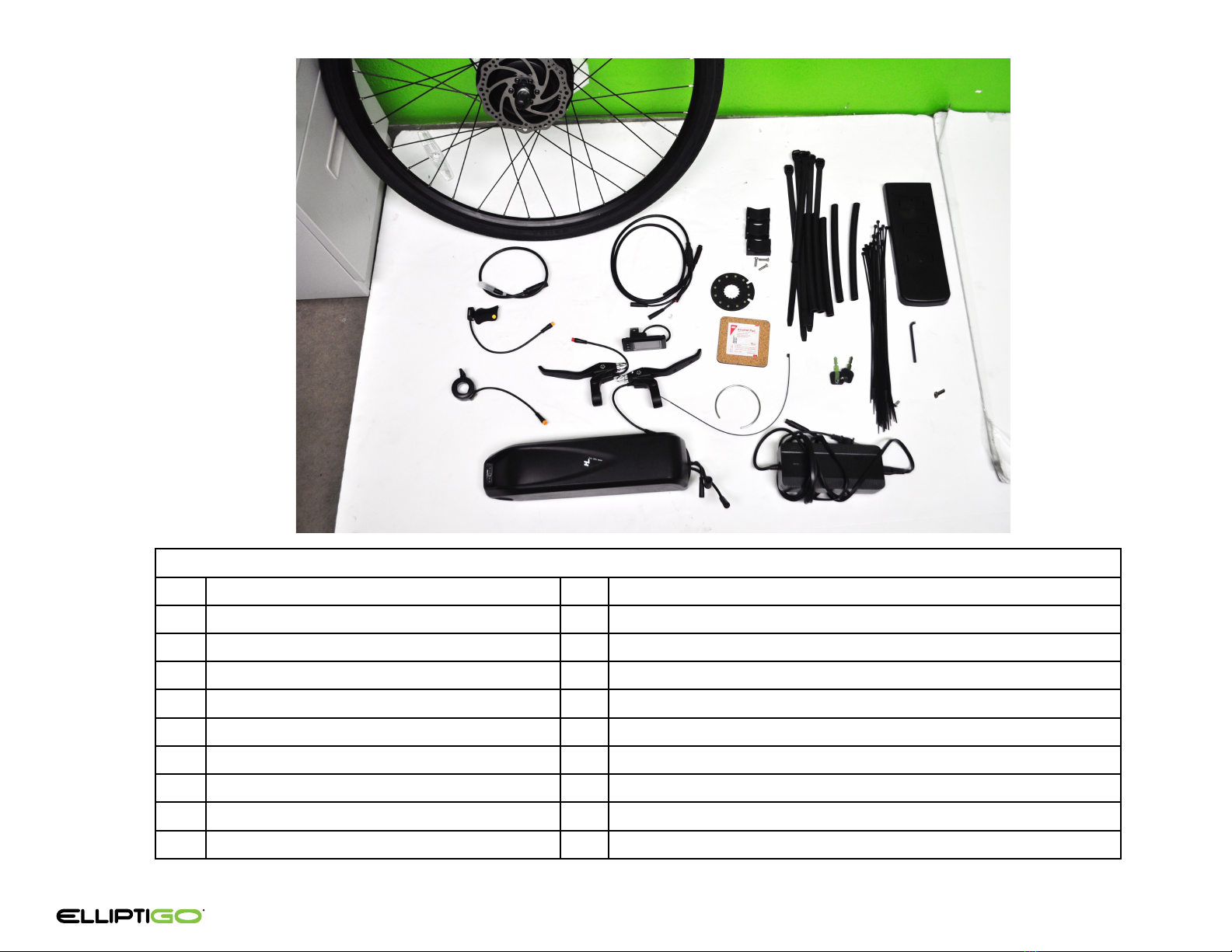
PARTS LIST
1 MOTORIZED REAR WHEEL 11 ALCOHOL PAD
2 MOTOR EXTENSION CABLE 12 PAS RETAINING RING AND ZIP TIE
3PAS SENSOR 13 ZIP TIES FOR BATTERY WITH RUBBER SLEEVES (4)
4 THROTTLE 14 SMALL ZIP TIES (25)
5 CONTROL HARNESS CABLE 15 BATTERY KEYS
6DISPLAY 16 BATTERY CHARGER
7BRAKE LEVERS WITH CUTOFF SWITCHES 17 BATTERY COVER
8 BATTERY AND CONTROLLER 18 BRAKE ADJUSTMENT WRENCH
9 BATTERY BRACKETS AND SCREWS (3) 19. TORQUE ARM SCREW
10 PAS MAGNETIC DISC
4
1.
2.
3.
4.
5.
6.
7.
8.
11.
12.
13.
15.
16.
17.
9.
14.
10.
18.
19.
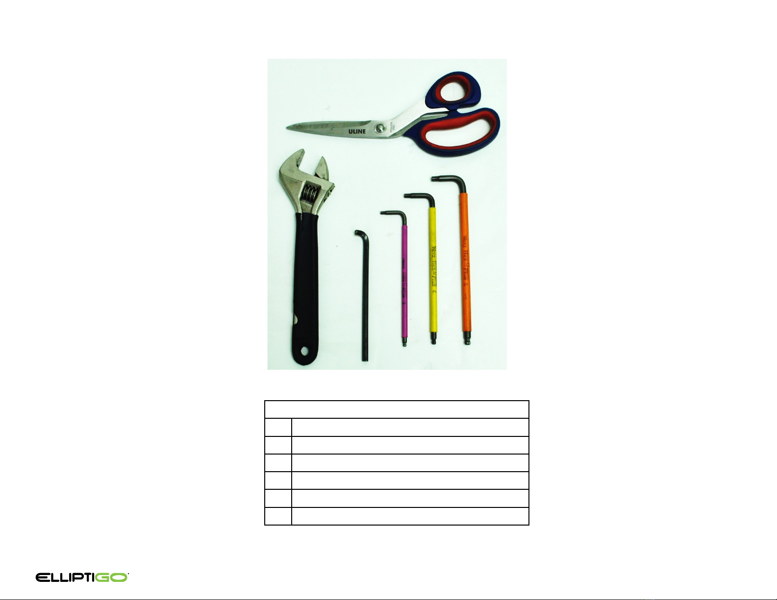
TOOLS REQUIRED
5
TOOLS REQUIRED
1. SCISSORS OR WIRE CUTTERS
2. ADJUSTABLE or 18MM WRENCH
3. BRAKE ADJUSTMENT WRENCH (INLCUDED)
4. 3MM ALLEN KEY
5. 4MM ALLEN KEY
6. 5MM ALLEN KEY
1.
2. 3. 4. 5. 6.

Battery Power Button and LED Indications
Your battery includes a power button, charging port, and a 4 LED
display.
Power Button
Use the power button to turn the battery on and off and to check the
charge level.
•
To turn the battery on
: Press and hold the power button for 10
seconds. The LED lights will light up as the battery turns on.
•
To turn the battery off:
Press and hold the power button for 10
seconds.
•
To check the charge level
: Quickly press and release the power
button when the battery is on. The LED lights will display the
charge level of the battery according to the table below.
THE BATTERY AND BATTERY CHARGER
6
4 LED display
The 4 LED display indicates when the battery is on, charging, the
charge level, and alarm codes.
•
Charging
: When the battery is charging, the 4 LED display
indicates the amount of charge as set forth in the following table:
•
Alarm Codes
: Battery malfunctions are shown as per the table:
Battery Handling
You must use caution when handling your battery. It is heavy and can
be damaged if dropped or handled roughly. Pay particular attention
to the “+” and “-” connection terminals located on the bottom of the
battery. They are exposed when the battery is not attached to the
bike. Take care not to damage them.
CAUTION! Avoid dropping or otherwise damaging your battery,
including the connection terminals. If you damage the battery. Do
not use it or charge it. Instead, contact customer service at
888.796.8227 or
service@elliptigo.com.
!
LED Indications Remaining Battery Capacity
91 - 100%
51 - 90%
11 – 50%
0 – 10%
OffOn
LED Indications (Charging) Remaining Battery Capacity
91 - 100%
51 - 90%
11 – 50%
0 – 10%
OffStaticBlinking
Alarm Indication
LED Behavior
Action
Out of Operating
Temperature Range
Let battery sit in ambient
temperature between
Issue With Current
Turn Battery Off and Then On
Voltage Too High or Low
Discharge or Charge the Battery
Other Issues
Contact ElliptiGO
OffStaticBlinking

Long-Term Battery Storage
If you need to store your battery for longer than two weeks, follow
these instructions to maintain your battery’s health and longevity:
•Charge or discharge the battery to approximately 60-75% of
maximum charge.
•Power off the battery.
•Store the battery in a dry, climate controlled, indoor location
between 50 °F – 77 °F (10 °C – 25 °C).
•Check the battery every 3 months, and if necessary, use the
charger that came with your kit to charge the battery to 60-75%
of maximum charge.
CAUTION! Failure to follow proper battery storage procedures
can result in a non-functional battery and void your warranty.
ADDITIONAL BATTERY SAFETY WARNINGS
WARNING! Do not open the battery housing. Opening the
battery housing voids the warranty, can damage the battery and
can cause fire, explosion or chemical burns resulting in damage to
property, serious injury and death.
WARNING! Do not expose the battery to excessive heat, fire or
mechanical shock. Exposing the battery to excessive heat, fire or
mechanical shock voids the warranty, can damage the battery and
can cause fire, explosion or chemical burns resulting in damage to
property, serious injury and death.
CAUTION! Keep batteries out of the reach of children. Batteries
present a serious danger to children.
CAUTION! Avoid storing your battery in direct sunlight. Storing
your battery in direct sunlight can damage the battery.
WARNING! If your battery begins to leak, do not allow the liquid
to come in contact with the skin or eyes. If you do contact the
liquid, wash the affected area thoroughly with soap and water and
seek medical advice.
When your battery is no longer operating as desired, dispose of it
properly in accordance with all local, state and federal laws.
THE BATTERY AND BATTERY CHARGER
7
!
!
!
!
!
Charger Safety Information
The charger works on 120/240 V 50/60 Hz standard home AC power
outlets. The charger is designed to generate heat when in operation.
As a result, the charger should only be used indoors in a cool, dry,
well-ventilated area and on a flat, stable, hard surface. Similarly, do
not cover the charger and keep it free from contact with liquids, dirt,
debris, or metal objects when in use. Store and use the charger in a
safe place away from children and where it cannot suffer damage
from falls or other impacts.
WARNING! If not treated properly, your charger could overheat
and start a fire. If the charger gets too hot to touch, you notice a
strange smell when charging, or you observe any other indication
that the charger may be overheating, discontinue charger use
immediately and contact ElliptiGO customer service at
888.796.8227 or service@elliptigo.com.
Only charge the battery using the provided charger or a replacement
charger purchased from ElliptiGO directly. Do not yank or pull on the
charger cables. When unplugging the charger, carefully remove the
cables by pulling on the plastic plugs, not pulling on the actual
cables.
WARNING! Using a charger other than the one included with this
kit or a replacement purchased directly from ElliptiGO can damage
your battery and cause a fire or explosion. Only charge the battery
with the correct charger.
Charging the Battery
Fully charge the battery prior to operating your bike for the first time.
You can charge the battery on its own or while it is attached to the
bike. Before charging your battery, always check the charger, charger
cables, and battery for damage. Place the charger and battery in a
safe area, free from direct sunlight and debris, and arranged so the
lights on each are visible. Arrange the charging cords so they are in
the least likely position for someone to trip over. Only charge the
battery in temperatures between 50 °F and 86 °F (10 °C and 30 °C).
WARNING! A damaged charger, battery or cables can result in a
fire or additional damage to your charger and/or battery. It is
critical that your charging system is free from damage before you
begin the charging process.
!
!
!
!

WARNING! Temperature is important when charging your
battery. Do not leave the battery or charger exposed to direct
sunlight or other direct heat sources. Ensure the ambient
temperature is between 50 °F and 86 °F (10 °C and 30 °C). If the
temperature is too hot, your battery can overheat which can lead
to an explosion and fire. If it is too cold, your battery may not
charge fully.
Charging Time
The battery may take longer to charge when fully depleted, when
very new, and after 3-5 years of regular use. If your battery does not
seem to be charging normally, taking longer to charge than
expected, or you are experiencing substantial reduction in range,
please discontinue use and contact ElliptiGO customer service
You should recharge your battery after each use. When the battery is
charging, the charge indicator light on the battery charger will be
red. When charging is complete, the indicator light will turn green. Do
not leave a charging battery unattended. Disconnect the battery
from the charger as soon as possible and always within one hour of
charge completion.
CAUTION! Avoid leaving a fully-charged battery connected to
the charger and never charge the battery for more than 12 hours at
a time. Doing so can lead to reduced battery life and may cause
your warranty to be voided.
THE BATTERY AND BATTERY CHARGER
8
!
!
Battery State of Charge Estimated Time to Fully Recharge
75% 1 hour and 40 minutes
50% 2 hours and 45 minutes
25% 3 hours and 50 minutes
0% 5 hours
This installation process is designed for two people. We highly
recommend following the installation video located on our
website: www.elliptigo.com/Ekit. These instructions are meant
to be used in conjunction with the video.
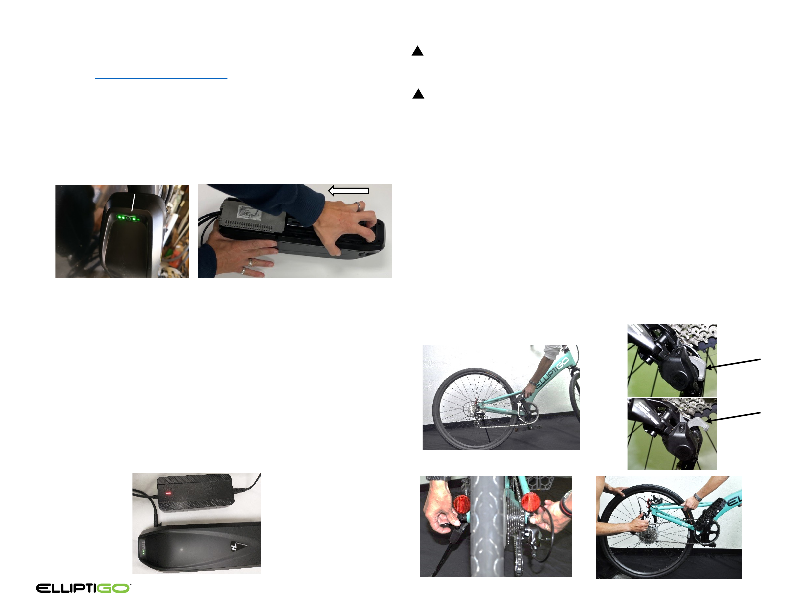
Step 1: Charge the Battery (5 Minutes)
1.1 Check that the battery is off by quickly pressing the button on the
battery (A). If no lights appear, the battery is off. If you see green
lights, the battery is on. To turn the battery off, press and hold
the button for about 10 seconds until the lights go away.
1.2 Remove the battery from the controller by facing the battery
down and placing your fingers in the front section of the plastic
receiver. Pull the controller toward the back of the battery to
dislodge the controller from the battery. Set the controller aside.
1.3 Open the charging port cover located on the battery’s side.
1.4 Place the charger on a flat, secure place between the battery and
a wall outlet. Connect the charger’s small cylindrical connector to
the charging port on the side of the battery and the regular plug
to a standard 120V power outlet. The light on the charger will
turn solid red when charging begins.
1.5 Charging is complete when the charger lights turn green. At that
point, unplug the charger from the wall and disconnect the
charger from the battery.
9
A
1.1
1.3-1.5
!
!
INSTALLATION
CAUTION! Always charge your battery in temperatures between
50 °F and 86 °F (10 °C – 30 °C) and ensure the battery and charger
are not damaged before initiating charge.
WARNING! Batteries are inherently dangerous objects that can
lead to explosions or fires if not treated properly. If you notice
anything unusual while charging, please discontinue charging and
use of the bike and contact ElliptiGO service at
service@elliptigo.com for assistance.
Step 2: Remove the Rear Wheel (5 Minutes)
2.1 With the bike on the kickstand, shift into the smallest sprocket by
leaning the bike against the kickstand so the rear wheel is off the
ground and then rotate the pedals with one hand while using the
shifter to shift into the highest gear with the other hand.
2.2 Open the clutch on the derailleur (MSUB only).
2.3 Open the quick release and then turn the quick release nut
counter-clockwise until there is enough space to remove the rear
wheel from the dropouts.
2.4 Pull the rear wheel out from the frame and set aside.
2.1
2.3 2.4
1.2
See the installation video at: www.elliptigo.com/Ekit
2.2 (MSUB only)
Closed
Open
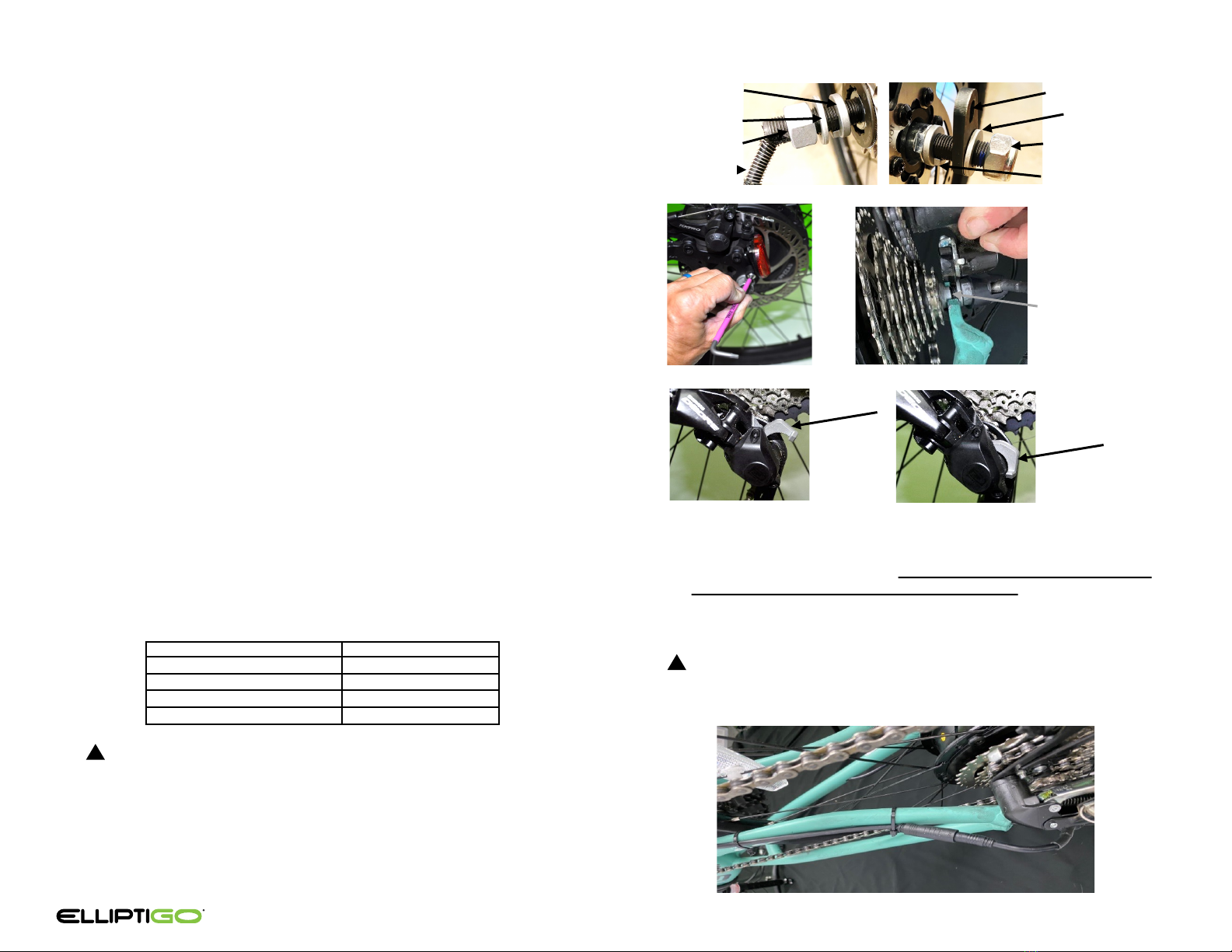
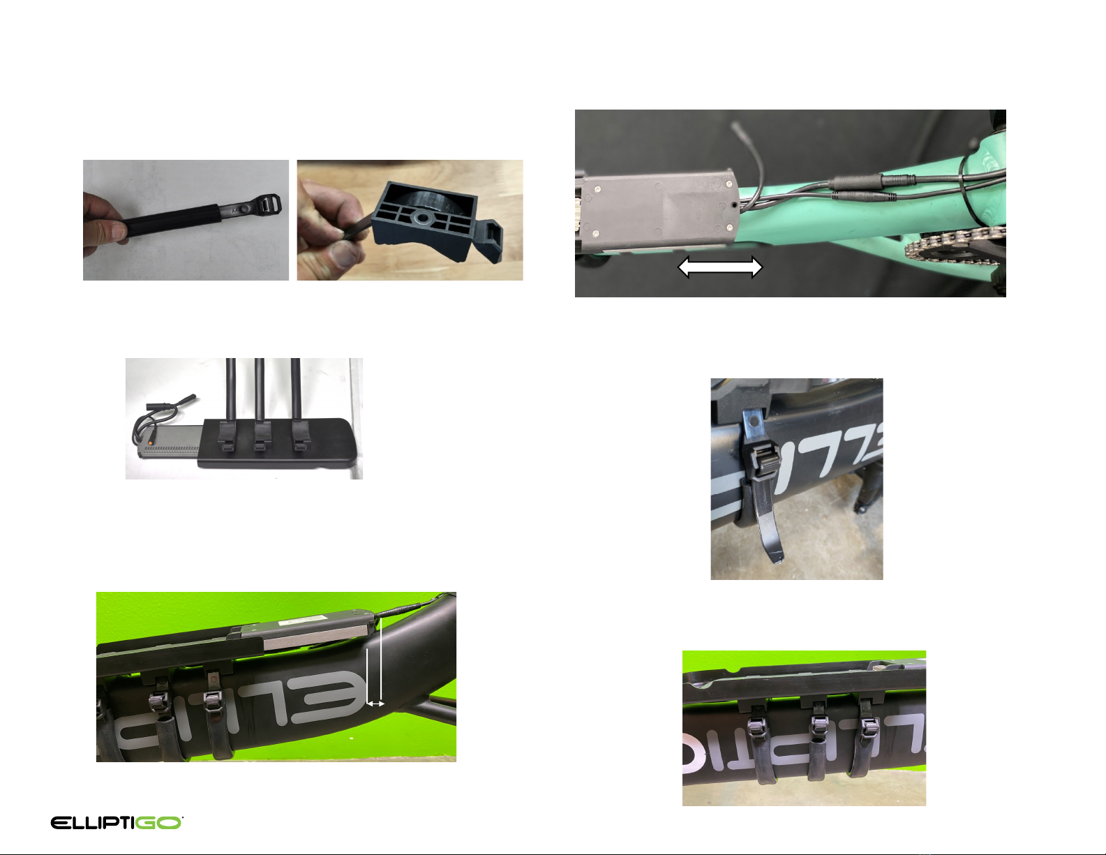
3.7 Align the arrow on the motor extension cable (#2) with the
arrow on the wheel cable connector. Connect the cables and
ensure they are seated. Use 3 small zip ties to route the cable
along the frame as shown.
Do not place any zip ties on the
short cable coming out of the wheel axle
. If you do, it will
make changing a tire later much more difficult. Trim the excess
ends of the cable ties. Note: Leave the other end of the motor
extension cable loose.
CAUTION! Do not use a zip tie on the short cable coming out
of the wheel axle. Using a zip tie there will impede your ability to
remove the rear wheel from the bike in the future.
Step 3: Install the motorized rear wheel. (15- 20 Minutes)
3.1 Remove the axle caps. Check that the axle with the Motor Cable
has a non-turn washer, flat washer and nut, in that order. Check
that the other side has a non-turn washer, torque arm, flat
washer and nut, in that order.
3.2 Using a 3mm Allen key, remove the reflector and hardware on
the side opposite the derailleur.
3.3 With the bike right side up, have your helper hold the front of
the bike. Orient the motorized wheel with the cassette on the
right side and the non-turn washer tabs pointed down. Loosen
the nuts several turns. Align the flat sides of the axle with the
dropouts. Use your wrench if necessary. Push the non-turn
washers against the motorized hub and push the flat washers
away from them. Insert the wheel into the frame so that the
dropouts sit between each non-turn washer and flat washer and
the torque arm is oriented so that the small slot lines up with
the threaded hole where the reflector was removed.
3.4 Once seated, close the derailleur clutch (MSUB only).
3.5 Insert the Torque Arm Screw (#19) through the slot in the
torque arm. Use a 3mm Allen key to thread it into the reflector
hole where the reflector was. Tighten to 5 N-m.
3.6 Tighten the axle nuts to 40 N-m. 40 N-m is tight! The chart
below shows the amount of force in pounds you need to apply
to the end of different-length wrenches in order to obtain a
torque of 40 N-m. The Nylox locknuts have more rotating
resistance than normal nuts. Ensure you have tightened them to
40 N-m. Cover with the rubber caps.
WARNING! It is critical to fully seat the wheel in the frame
with the non-turn washer tabs facing downwards and engaged
within each dropout and to tighten each nut to 40 N-m. Failure
to do so could result in the wheel detaching from the bike, which
would cause the rider to lose control and suffer a fall.
INSTALLATION
10
3.3
3.7
Non-Turn Washer
Tab Oriented Down
(View from
Underneath)
(Underneath view)
!
See the installation video at: www.elliptigo.com/Ekit
Closed
Open
3.4 MSUB Only – Closing the Clutch
Wrench Length (inches) Force (pounds)
659
844
10 35
12 30
!
3.2
Nut
Flat Washer
No Turn Washer
Nut
Flat Washer
No Turn Washer
Torque Arm
Motor Cable

4.5 Use the alcohol pad to clean the surface of the bottom bracket.
4.6 Remove the backing from the adhesive on the PAS sensor (#3).
Rotate the crank so that the zip tie is inline with the sensor. Align
the PAS sensor so that the face is parallel with the disc surface and
there is about a 1/16 inch gap between the zip tie and sensor. You
can use a credit card to establish the gap. Press down on the PAS
sensor to adhere it to the bottom bracket. Apply additional pressure
for about 30 seconds to fully activate the adhesive.
4.7 Route the PAS and motor extension cables as shown and secure
them using 2 small zip ties. Trim off the excess zip tie.
Step 4: Install the Pedal Assist System Sensor (20-30 Minutes)
4.1 Have your helper help you turn the bike upside down.
4.2 Remove the retaining ring (#13) from the PAS magnet disc (#11).
Pull to separate the disc into two pieces.
4.3 Install the PAS magnet disc on the right crank. Make sure the face of
the disc labeled “working surface” (A) is facing inward toward the
bike frame. Press the two pieces together. Install the retaining ring
back around the disc. If the two pieces do not fully seat together,
that is OK, the retaining ring will keep them together.
4.4 Secure the magnet disc to one of the legs of the crank spider using
a small zip tie. Make sure the head of the zip tie sits on the outside
of the crank spider, away from the bike. Trim off the excess zip tie.
INSTALLATION
11
4.2
4.3
4.5
4.6
4.4
Small gap between
sensor and zip tie
See the installation video at: www.elliptigo.com/Ekit
A
Zip Tie
Gap between
sensor and zip tie
Zip Ties
4.7
INSTALLATION
12
See the installation video at: www.elliptigo.com/Ekit
Step 5: Install the Controller (20 – 30 Minutes)
5.1 Remove the rubber sleeves from the large zip ties (#14).
5.2 Slide a large zip tie through the slots in each battery bracket
(#9) until it stops.
5.3 Using a 3mm Allen key, attach the battery cover (#17) to the
controller with the three battery bracket screws (#10) and then
use the screws to attach the three brackets. Tighten to 5 N-m.
5.4 Slide the rubber sleeves over the zip ties.
5.5 Orient the controller so that the cables are facing the rear of the
bike. Align the rear of the controller about 1 inch behind the
edge of the “E” in the ElliptiGO logo on the right side of the
bike. Very loosely close the zip ties. DO NOT TIGHTEN YET!
5.1 5.2
5.3
5.6 Connect the PAS and Motor extension cables to the controller.
Adjust the controller position to eliminate cable slack.
5.7 Once the controller is positioned so that there is no slack in the
connected cables, tighten the zip ties. Once tight, route the zip
tie end back through the zip tie buckle.
5.8 Trim off the excess length of the zip ties with scissors.
1”
5.5
5.7
5.8
5.6

INSTALLATION
13
Step 6: Attach the Controls (20-30 Minutes)
6.1 Turn the bike right side up and put the kickstand down.
6.2 Remove the grips from the handlebar using a 3mm Allen key.
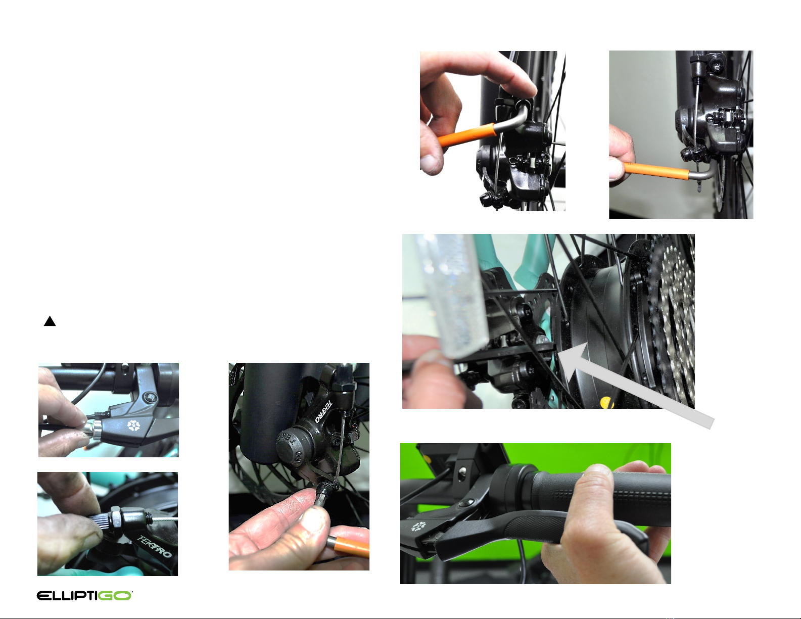
6.3 Detach the brake cables from the brake levers by aligning the slots
in the barrel adjuster, locking ring and front of the brake body.
Next pull the cable housing out of the barrel adjuster so that the
bare cable is visible. Then slide the bare cable through the aligned
slots in the barrel adjuster, locking ring and brake body. Pull the
brake lever and remove the gray brake cable anchor out of the
capturing hole.
6.4 Remove the brake levers from the handlebar with a 4mm Allen
key.
6.5 Orient the display (#6) as shown and slide it onto the left
handlebar. Do not tighten yet.
6.6 Orient each brake lever (#7) so the gray star symbol is facing up
and away from the handlebar and each lever is pointing outboard.
Slide each brake lever onto the handlebar. Do not tighten yet.
6.7 Attach the brake cables to the levers by aligning the slots in the
barrel adjuster, locking ring and brake body. Seat the gray brake
cable anchor into the brake lever hole and route the exposed cable
through the aligned slots. Then insert the cable housing into the
barrel adjuster.
Note: If you need more slack to attach the cable,
loosen the brake caliper pinch bolt located on the brake.
6.8 Orient the throttle (#4) with the screw facing down. Slide it onto
the left handlebar until it is next to the brake. Do not tighten yet.
6.9 Slide each grip onto its respective end of the handlebar. Ensure
that the grip is fully seated on the handlebar. You may need to
slide the shifter, throttle, display and brake levers further in on the
handlebar to enable the grips to fully seat. Once seated, use a 3mm
Allen key to tighten the screw to 3 N-m.
WARNING! Failing to fully seat the grips onto the handlebar and to
tighten them sufficiently could cause the grips to come off while
riding, which would cause the rider to lose control and fall.
6.10 Fine tune the positioning of the shifter, throttle, display and brake
levers until they are correctly aligned. Then tighten the display and
throttle to 3 N-m using a 3mm Allen key and tighten the brake
levers and shifter to 5 N-m with a 4mm Allen key.
!
See the installation video at: www.elliptigo.com/Ekit
6.2 6.3
6.4 6.5
6.6
6.7 – 6.10
INSTALLATION
14
Step 7: Adjust the Brakes (10 – 15 Minutes)
7.1 Tighten down each barrel adjuster at the brake lever and
caliper by rotating it clockwise until it stops.
7.2 Loosen the cable pinch bolt on the brake caliper arm.
7.3 Eliminate the slack in the cable without actuating the brake
caliper arm and then re-tighten the pinch bolt to 4 N-m.
7.4 Using a 5mm Allen key, loosen the two caliper mounting
bolts just enough to allow the caliper body to laterally float
on the bracket, but not enough to have a significant gap
between the two surfaces. You should be able to move the
caliper side to side easily with your hand.
7.5 Use the Brake Adjustment Wrench (#18) included with the
kit to turn the adjustment screw on the fixed inner pad
clockwise until the resistance increases. Then, loosen it
slightly by making a 1/2 counter-clockwise turn.
7.6 Pull and hold the brake lever firmly with one hand to align
the caliper with the rotor. With the other hand, tighten both
caliper bolts to 6 N-m.
WARNING! Ensure you tighten each caliper bolt to 6 N-m.
Failure to properly tighten these bolts can cause your brake to
malfunction, which could lead to a fall.
See the installation video at: www.elliptigo.com/EKit
!
7.1 7.2
7.4 7.4
7.5
7.6
Brake
Adjustment
Wrench inserted
in Adjustment
Screw

INSTALLATION
15
Step 7: Adjust the Brakes (Continued)
7.7 Release the brake lever. Spin the wheel and confirm there is
no rubbing. Look to see that the fixed pad sits parallel to the
rotor surface less than 1/16 of an inch away.
7.8 If the rotor is rubbing on the fixed pad, turn the adjustment
screw counter-clockwise 1/4 turn and recheck. Repeat this
step until the rubbing is eliminated.
7.9 Adjust the other pad by turning the barrel adjuster on the
brake caliper counter-clockwise until the pad just contacts
the rotor. Then turn the barrel adjuster clockwise 1/4 turn. If
the caliper barrel adjuster does not have at least 3 threads
of engagement, then tighten it back down until it has at
least that amount of engagement and use the barrel
adjuster on the brake lever to make this adjustment.
WARNING! Ensure the caliper barrel adjuster has at least
three (3) threads of engagement. Failure to do so can cause
the brake to fail and lead to a fall.
7.10 Squeeze the brake lever three times. Spin the wheel and
check for rubbing. If the outer pad rubs then turn the barrel
adjuster 1/4 turn and recheck. Repeat this step until the
rubbing is eliminated.
7.11 Squeeze the lever and make sure that the brake had full
braking force before the lever hits the grip. Tighten the lock
nuts on both barrel adjusters.
WARNING! Ensure that the brake levers stop before
contacting the grip. If the brake levers contact the grip, then
the brakes may not be providing full braking force to the
rotor. This could result in the rider not being able to stop as
quickly as necessary in certain circumstances, which could
lead to a fall.
See the installation video at: www.elliptigo.com/EKit
!
!
7.9 -
Alternative
Brake Lever Barrel Adjuster
7.9 -
Primary
Caliper Barrel Adjuster

Step 8: Connect the Wire Harness (15-20 Minutes)
8.1 Raise the steering column to the “MAX. EXTENSION” mark.
8.2 Connect the brake levers, display and throttle to the control
harness cable (#5). The connectors are color coded: the brakes
are red, the display is green, and the throttle is orange.
8.3 Connect the other end of the control harness cable and the
loose end of the motor extension cable to the connectors on
the controller. Route the cables as shown using 10 small zip ties.
Coil up the excess cable in the front section of the frame. Trim
off the excess zip tie ends.
WARNING! Ensure that the cables always stay close to the
frame members and that any extra slack can not get caught in
any of the bike’s moving mechanisms. Allowing the cable to get
caught in a moving mechanism could cause the rider to lose
control and fall.
INSTALLATION
16
8.1
8.2
8.3
8.3
!
See the installation video at: www.elliptigo.com/Ekit
“MAX EXTENSION” Line
Zip Ties
Zip Ties
Connectors
INSTALLATION
17
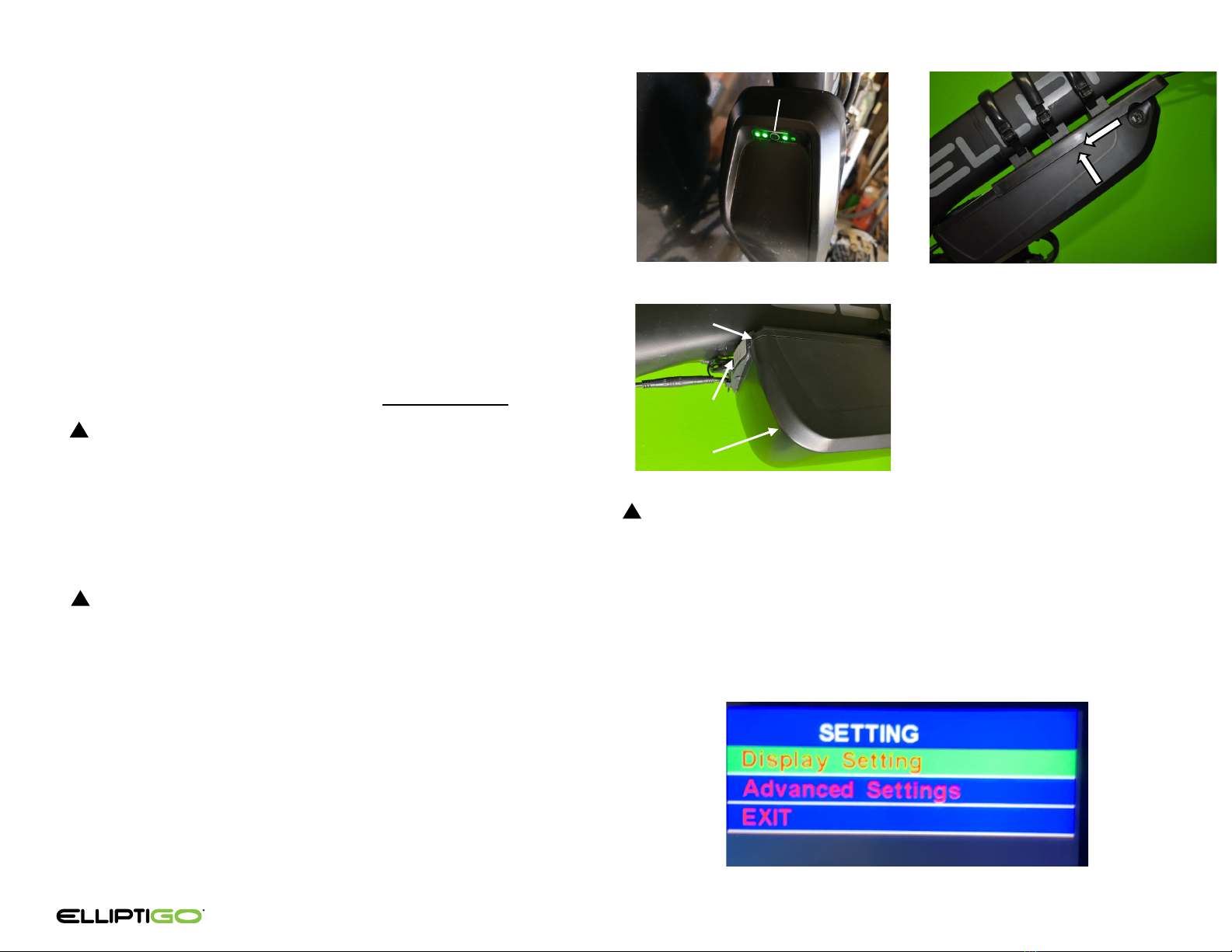
Step 9: Check the Display Settings (5-10 Minutes)
9.1 Once your battery is fully charged, unplug it from the charger.
Ensure the battery is off by short pressing the button on the
battery (A). If no lights appear, the battery is off. If green lights
appear, the battery is on. Turn the battery off by pressing and
holding the button for about 10 seconds until the lights go off.
9.2 Align the battery so that the battery button is facing down and
oriented towards the front of the bike. Align the tabs on the
battery with those on the battery receiver portion of the
controller. Lift the battery into the receiver and while keeping
the battery vertically seated, gently slide it rearward to capture
it into the receiver. Note the small tabs at the back of the
controller and ensure the battery slides over them. Make sure
the battery is fully seated by ensuring it sits flush with the edge
of the controller.
9.3 Insert the key into the battery. Turn the key clockwise to lock
the battery to the battery receiver. Remove the key.
WARNING! Failure to properly seat and/or lock the battery to
the receiver using the key prior to riding or transporting your bike
could allow the battery to detach from the bike resulting in injury
and/or damage to the battery and bike.
9.4 Ensure the battery has been properly secured to the bike before
each use by confirming that it is locked and then carefully
pulling backward on the battery with both hands to test that
the battery is secured to the receiver.
WARNING! Ensure the key is removed from the battery before
mounting or operating the bike. Leaving the key inside of the
battery key barrel while mounting, operating the bike, pedaling,
dismounting, and/or removing an unlocked battery from the
frame can damage the key or battery, and/or lead to an injury.
9.5 Turn on the battery by pressing and holding the battery button
for 10 seconds until the lights turn on. Then turn on the display
by pressing and holding the on/off button until the display
lights up (about 3 seconds). Keep one hand near the brake
levers at all times in case you inadvertently hit the throttle or
rotate the crank arms.
9.3
9.2
A
9.1 & 9.5
!
!
CAUTION! Once the battery and display are turned on, pressing
the throttle or rotating the cranks will activate the motor, causing
the bike to roll forward. It is critical that you keep your right hand
ready to squeeze the brake lever at all times when the display is
turned on. Squeezing the brake lever will cut off power to the
motor. Failure to react to an unexpected movement of the bike
could injure you or someone else or damage property.
9.6 Press and hold both the + and – buttons simultaneously for 3
seconds to enter the “SETTING” menu.
!
9.6
See the installation video at: www.elliptigo.com/Ekit
No Gap
Controller
Battery

INSTALLATION
18
Step 9: Check the Display Settings (Continued)
9.7 Quickly press and release the power button to select “Display
Setting.” Confirm that the settings are set to the following:
If a setting is incorrect, press the “-” button to highlight it. Press
the power button quickly to enter the adjustment functionality.
Press the “+” to correct the setting.
9.8 To exit the setting, quickly press and release the power button.
Navigate to “BACK” using the – button. Quickly press and
release the power button to return to the “SETTING” menu.
9.9 Press the – button to highlight “Advanced Settings.” Quickly
press and release the power button to select “Advanced
Settings.” Confirm that the settings are set to the following:
If a setting is incorrect, press the “-” button to highlight it. Press
the power button quickly to enter the adjustment functionality.
Press the “+” to correct the setting.
B
No Gap
9.10 To exit the setting, quickly press and release the power button.
Navigate to “BACK” using the – button. Quickly press and
release the power button to return to the “SETTING” menu.
Once on the SETTING menu, use the “-” button to highlight
“EXIT.” Quickly press and release the power button to exit the
setting menu.
CAUTION! Incorrect settings can prevent the kit from working
properly.
9.7
!
See the installation video at: www.elliptigo.com/Ekit
9.9
This manual suits for next models
1
Table of contents


