SRAM RockShox Vivid Air Series User manual

2011 Technical Manual

SRAM LLC WARRANTY
EXTENT OF LIMITED WARRANTY
SRAM warrants its products to be free from defects in materials or workmanship for a period of two years
after original purchase. This warranty only applies to the original owner and is not transferable. Claims under
this warranty must be made through the retailer where the bicycle or the SRAM component was purchased.
Original proof of purchase is required.
LOCAL LAW
This warranty statement gives the customer specific legal rights. The customer may also have other rights
which vary from state to state (USA), from province to province (Canada), and from country to country
elsewhere in the world.
To the extent that this warranty statement is inconsistent with the local law, this warranty shall be deemed
modified to be consistent with such law, under such local law, certain disclaimers and limitations of this
warranty statement may apply to the customer. For example, some states in the United States of America, as
well as some governments outside of the United States (including provinces in Canada) may:
Preclude the disclaimers and limitations of this warranty statement from limiting the statutory rightsa.
of the consumer (e.g. United Kingdom).
Otherwise restrict the ability of a manufacturer to enforce such disclaimers or limitations.b.
LIMITATIONS OF LIABILITY
To the extent allowed by local law, except for the obligations specifically set forth in this warranty statement,
in no event shall SRAM or its third party supplies be liable for direct, indirect, special, incidental, or
consequential damages.
LIMITATIONS OF WARRANTY
This warranty does not apply to products that have been incorrectly installed and/or adjusted according to
the respective SRAM technical installation manual. The SRAM installation manuals can be found online at
www.sram.com, www.rockshox.com, www.avidbike.com, www.truvativ.com, or www.zipp.com.
This warranty does not apply to damage to the product caused by a crash, impact, abuse of the product,
non-compliance with manufacturers specifications of usage or any other circumstances in which the
product has been subjected to forces or loads beyond its design.
This warranty does not apply when the product has been modified.
This warranty does not apply when the serial number or production code has been deliberately altered,
defaced or removed.
This warranty does not apply to normal wear and tear. Wear and tear parts are subject to damage as a
result of normal use, failure to service according to SRAM recommendations and/or riding or installation in
conditions or applications other than recommended.
WEAR AND TEAR PARTS ARE IDENTIFIED AS:
Dust seals/Bushings/Air sealing o-rings/Glide rings/Rubber moving parts/Foam rings/Rear shock
mounting hardware and main seals/Stripped threads and bolts (aluminum,titanium, magnesium or steel)/
Upper tubes (stanchions)/Brake sleeves/Brake pads/Chains/Sprockets/Cassettes/Shifter and brake
cables (inner and outer)/Handlebar grips/Shifter grips/Jockey wheels/Disc brake rotors/Wheel braking
surfaces/Bottom out pads/Bearings/Bearing Races/Pawls/Transmission gears/Spokes/Free hubs/
Aero bar pads/Corrosion/Tools
This warranty shall not cover damages caused by the use of parts of different manufacturers.
This warranty shall not cover damages caused by the use of parts that are not compatible, suitable and/or
authorized by SRAM for use with SRAM components.
This warranty shall not cover damages resulting from commercial (rental) use.
ROCKSHOX SUSPENSION SERVICE
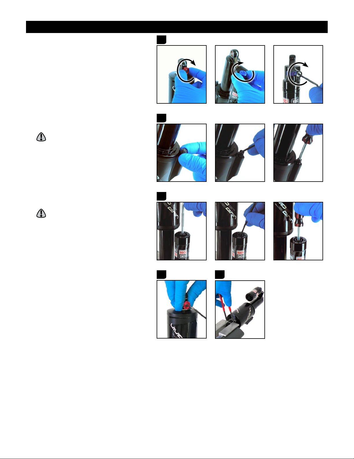
We recommend that you have your RockShox suspension serviced by a qualified bicycle mechanic.
Servicing RockShox suspension requires knowledge of suspension components as well as the special
tools and fluids used for service.
Used suspension fluid should be recycled or disposed of in accordance to local and federal regulations.
NEVER pour suspension fluid down a sewage or drainage system or into the ground or a body of water.
This publication includes trademarks and registered trademarks of SRAM LLC designated by the symbols ™ and ®, respectively.
Copyright © SRAM LLC 2010
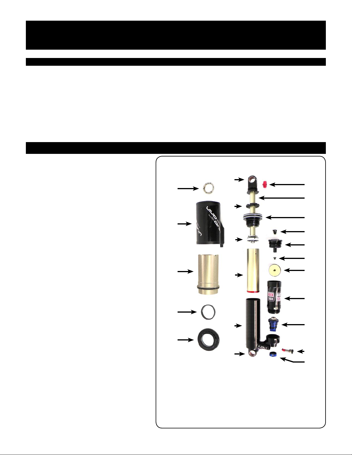
For exploded diagram and part number information, please refer to the Spare Parts Catalog available on our web site at www.sram.com.
For order information, please contact your local SRAM distributor or dealer.
Information contained in this document is subject to change at any time without prior notice.
Your product‘s appearance may differ from the pictures/diagrams contained in this document.
Product names used in this document may be trademarks or registered trademarks of others.

GEN.0000000003161 REV A3
TABLE OF CONTENTS
TOOLS NEEDED FOR SERVICE ..........................................................................................................................................................................................................5
MOUNTING HARDWARE & BUSHING SERVICE ...........................................................................................................................................................................6
MOUNTING HARDWARE REMOVAL............................................................................................................................................................................................................... 6
BUSHING REMOVAL............................................................................................................................................................................................................................................ 7
BUSHING INSTALLATION.................................................................................................................................................................................................................................. 7
MOUNTING HARDWARE INSTALLATION ..................................................................................................................................................................................................... 8
VIVID AIR SERVICE...............................................................................................................................................................................................................................9
GETTING STARTED ............................................................................................................................................................................................................................................. 9
AIR CAN REMOVAL (ROUTINE SERVICE) .................................................................................................................................................................................................... 10
AIR CAN SERVICE (ROUTINE SERVICE)....................................................................................................................................................................................................... 12
SHOCK BODY DISASSEMBLY (ROUTINE SERVICE) .................................................................................................................................................................................. 13
SHOCK BODY SHAFT ASSEMBLY SERVICE (ROUTINE SERVICE) ......................................................................................................................................................... 14
SHAFT EYELET SERVICE (COMPREHENSIVE SERVICE).......................................................................................................................................................................... 15
SHOCK BODY/DAMPER SHAFT ASSEMBLY SERVICE (ROUTINE SERVICE) ...................................................................................................................................... 16
IFP RESERVOIR SERVICE (ROUTINE SERVICE) .......................................................................................................................................................................................... 16
R2C ONLY: LOW SPEED COMPRESSION VALVE SERVICE (COMPREHENSIVE SERVICE).............................................................................................................. 17
ENDING STROKE REBOUND SERVICE (COMPREHENSIVE SERVICE).................................................................................................................................................. 19
SHOCK RE-ASSEMBLY & BLEED PROCEDURES (ROUTINE SERVICE)................................................................................................................................................ 20
AIR CAN INSTALLATION (ROUTINE SERVICE) .......................................................................................................................................................................................... 24

GEN.0000000003161 REV A4
SAFETY FIRST!
At SRAM, we care about YOU. Please, always wear your safety glasses
and protective gloves when servicing your RockShox suspension.
Protect yourself! Wear your safety gear!

GEN.0000000003161 REV A5
TOOLS NEEDED FOR SERVICE
The following chart is a list of the model year 2011 tools needed for service on your Vivid Air rear shock. While this chart is
intended to be comprehensive, it is still only a guide. The tools required for each step of service are detailed in the text of the
service section.
TOOLS
Safety/Starting Equipment
Safety Glasses
Nitrile Gloves
Apron
Clean Rags (Lint Free)
Oil Measuring Device
Oil Pan
Clean Work Area
Bench Vice
Soft Jaws
General Tools
2 mm Hex
2.5 mm Hex
4 mm Hex
13 mm Open-End/Box Wrench
30 mm Flat Wrench
Adjustable Wrench
Torque Wrench
Open-End 16 Notch External Bottom Bracket Tool With A
35 mm Opening (Such As The Pedro's®Shimano®Integrated Bottom Bracket
Wrench)
Sharp Pick
Schrader Valve Core Removal Tool
T10 TORX®Wrench
Spanner Wrench
Felt Tip Pen
SRAM Tools
Mounting Hardware/Eyelet Bushing Tool
Shaft Clamps
Gauged Shock Pump
Vivid Air Pump Adapter (For IFP Reservoir)
Vivid Air Can Wrench
2011 24 mm Pin Spanner
Oil/Liquids
Air Can Lube (Maxima®Maxum4 Extra 15w50)
Suspension Oil (RockShox 3wt)
Grease (Parker®O-Lube)
Isopropyl Alcohol
Red Threadlock

GEN.0000000003161 REV A6
MOUNTING HARDWARE & BUSHING SERVICE
Prior to servicing your rear shock, you will first need to remove it from your bicycle frame according to your bicycle
manufacturer's instructions. Once your shock is off your bicycle, you will need to remove the mounting hardware before
performing any service.
Any time you need to clamp the rear shock eyelets into a vise, use aluminum soft jaws to prevent damage to the eyelets.
MOUNTING HARDWARE REMOVAL
Some mounting hardware is easily removed
using only your fingers. Try to remove the end
spacers with your fingernail, then push the
bushing pin out of the bushing. If this works,
move on to the next section titled "Bushing
Service".
If you are unable to remove your mounting
hardware using your fingers, use the SRAM rear
shock bushing installation and removal tool.
Thread the push pin onto the threaded rod, small1.
diameter end first, until the rod is flush with or
slightly protrudes from the hex-shaped end of
the push pin.
Insert the threaded rod through the shock eyelet2.
so that the push pin rests against the bushing
pin.
Thread the catcher, with the large open end first,3.
along the rod until it rests over the end spacer on
the opposite side of the bushing pin.
Clamp the catcher in a vise or hold it secure with4.
a 13 mm or adjustable wrench. Use a second 13
mm open ended or adjustable wrench to thread
the push pin along the rod until it stops against
the end spacer. Unthread the push pin from the
threaded rod and remove the end spacer from
that side.
Re-install the push pin onto the threaded rod and5.
hand thread it along the rod until it rests against
the bushing pin (inside the shock eyelet bushing)
again. Use a 13 mm wrench to thread the push
pin along the rod until it stops against the shock
eyelet.
Unthread the catcher from the threaded rod.6.
Remove the end spacer from the threaded rod
and the bushing pin from the catcher. Remove
the push pin and threaded rod from the shock.
Set the mounting hardware aside until you have
finished servicing your shock. Repeat for the
other eyelet.
2
Threaded rod
Push pinCatcher
Rear shock bushing installation/removal tool
1 3
4 5 6

GEN.0000000003161 REV A7
BUSHING SERVICE
To replace damaged or worn out bushings, use
the RockShox rear shock bushing installation
and removal tool.
BUSHING REMOVAL
Insert the threaded rod through the shock eyelet1.
so that the base of the push pin rests against the
bushing.
Thread the catcher, with the large open end first,2.
along the rod until it rests on the opposite side of
the shock eyelet.
Clamp the catcher in a vise or hold it secure with3.
a 13 mm or adjustable wrench. Use a second 13
mm open ended wrench, an adjustable wrench,
or a socket wrench with a 13 mm socket to
thread the push pin along the rod until the push
pin rests against the shock eyelet.
Unthread the catcher from the threaded rod.4.
Remove the tool from the shock eyelet and
discard the old bushing. Repeat for other eyelet.
BUSHING INSTALLATION
Apply a small amount of grease to the outside of5.
the new bushing.
Position the shock eyelet and bushing between6.
the soft jaws of a vise. Slowly turn the vise
handle to begin pressing the bushing into the
shock body.
Check the alignment of the bushing as it enters
the eyelet. If the bushing starts to enter the
eyelet at an angle, remove the bushing from the
eyelet, regrease the bushing, and repeat this
step until the bushing enters the eyelet straight.
To prevent damage to the shock, position the
eyelet in the vise so that the adjustment knobs
are clear of the vise jaws.
Continue to press the bushing until it is7.
completely seated in the eyelet.
Remove the shock from the vise and repeat the8.
installation process for the other bushing and
eyelet.
1 2
34 5
6
7

GEN.0000000003161 REV A8
MOUNTING HARDWARE INSTALLATION
Some mounting hardware is easily installed
using only your fingers. Press the bushing
pin into the shock eyelet bushing until the
pin protrudes from both sides of the eyelet
an equal amount. Then press an end spacer,
large diameter side first, completely onto each
end of the bushing pin. If this works, you have
completed mounting hardware and bushing
service.
If you are unable to install your mounting
hardware using your fingers, use the SRAM rear
shock bushing installation and removal tool.
Thread the push pin onto the threaded rod, small1.
diameter end first, until the rod is flush with or
slightly protrudes from the hex-shaped end of
the push pin.
Insert the threaded rod through the bushing2.
pin then through the shock eyelet so that the
bushing pin is positioned between the push pin
and the shock eyelet.
On the opposite side of the shock eyelet, thread3.
the catcher, opening side first, along the rod until
it rests against the shock eyelet.
Clamp the catcher in a vise or hold it secure with4.
a 13 mm or adjustable wrench. Use a second 13
mm open ended wrench, an adjustable wrench,
or a socket wrench with a 13 mm socket to
thread the push pin along the rod so that it
pushes the bushing pin into the shock eyelet
bushing. Continue to thread the push pin and
push the bushing pin into the shock eyelet
bushing until the bushing pin protrudes from
both sides of the eyelet an equal amount (you
may need to unthread the catcher slightly to
check the bushing pin spacing).
Unthread the catcher from the threaded rod and5.
remove the tool from the shock eyelet.
Use your fingers to push an end spacer onto6.
each end of the bushing pin, with the large
diameter side of the spacers facing the shock
eyelet.
1 2
4
3
6

GEN.0000000003161 REV A9
VIVID AIR SERVICE
INTRODUCTION
Prior to servicing your rear shock, you will first need to remove it from your bicycle frame according to your bicycle
manufacturer's instructions. Once your shock is off your bicycle, remove the rear shock mount hardware. Rear shock mount
hardware removal instructions can be found in the "Mounting Hardware and Bushing Service" section of this document.
Vivid rear shock service includes instructions for completing both routine and comprehensive service procedures. Routine
service procedures are maintenance items that should be performed at regular intervals in order to keep your shock functioning
optimally. Comprehensive service procedures are long-term maintenance items that should be performed periodically as a
supplement to the routine service items. When performing routine service intervals, you only have to complete the sections titled
'Routine Service'. When performing comprehensive service intervals, you will complete all instructions, in order, including the
routine service procedures.
SERVICE INSTRUCTIONS
GETTING STARTED
Remove the shock mounting hardware (see1.
the "Mounting Hardware And Bushing Service"
section).
Place an oil pan on the floor underneath the area2.
of the shock. Place a large oil absorbing rag
directly underneath the vise where the shock
will be clamped to catch all oil that will spill from
the shock during service.
Check and record your current air pressure3.
setting to assist with post-service set up.
EXPLODED VIEW - VIVID AIR REAR SHOCK ASSEMBLY
U
A
C
E
T
S
R
Q
P
O
L
N
M
I
H
G
B
J
K
F
V
D
A. Air can lock ring I. Damper inner sleeve Q. IFP bleed screw
B. Air can J. Shock body R. IFP
C. Air can inner sleeve K. Body eyelet S. IFP reservoir
D. Top out bumper L. Rebound adjuster knob T. Low Speed Compression
assembly (R2C)
E. Air seal head M. Shaft
F. Shaft eyelet N. Seal head/air piston U. Ending Stroke Rebound
assembly
G. Bottom out bumper O. Nitrogen fill cap
H. Piston P. IFP reservoir cap V. Low Speed Compression
adjuster knob (R2C)

GEN.0000000003161 REV A10
SERVICE INSTRUCTIONS (CONTINUED)
Turn the Beginning Stroke Rebound and the4.
Low Speed Compression (R2C only) adjusters
clockwise, until they stop. Use a 2.5 mm hex
to turn the Ending Stroke Rebound adjuster
clockwise until it stops.
Count each detent click as you turn the adjuster
and record the number of clicks to assist with
post-service set-up.
AIR CAN REMOVAL (ROUTINE SERVICE)
Remove the air can valve cap. Use a small hex or5.
pick to depress the Schrader valve and release
all air pressure from the air can. Use a Schrader
valve tool to remove the valve core.
CAUTION
Failure to remove all air pressure can lead
to personal injury during air can
disassembly.
Use a T10 TORX TORX6. ® to remove the air cap
from the IFP (Internal Floating Piston) reservoir.
Use a small hex or pick to depress the Schrader
valve and release all air pressure from the IFP
reservoir. Use a Schrader valve tool to remove
the Schrader valve core.
CAUTION
Failure to remove all air pressure can lead
to personal injury during IFP reservoir
disassembly.
Use a 2.5 mm hex to remove the rebound7.
adjuster knob bolt. Remove the rebound adjuster
knob from the shaft eyelet.
Insert the tips of the spanner tool into the8.
holes of air can retaining ring, which is located
between the air can and shaft eyelet. Clamp the
shock rebound eyelet between the soft jaws of a
vise, leaving just enough room for the spanner to
rotate, but not come out of the retaining ring.
5
4
6
7 8

GEN.0000000003161 REV A11
SERVICE INSTRUCTIONS (CONTINUED)
Use the spanner tool to unthread the air can9.
retaining ring from the shaft eyelet. Remove the
shock from the vise and remove the retaining
ring from the shaft eyelet.
Wrap electrical tape around the shock body,10.
starting from the air can and extending
approximately half the length of the shock body.
This will prevent damage to the surface of the
shock body during air can removal.
Clamp the SRAM Vivid Air Can Wrench into11.
a vise. Place the shock, by the air can, in the
SRAM Vivid Air Can Wrench, body eyelet side
up. Use an open ended 16 notch external bottom
bracket tool with a 35 mm opening to loosen
the air can seal head, located at the bottom of
the air can. Turn the tool counter-clockwise to
unthread the seal head completely from the air
can.
Remove the shock from the SRAM Vivid Air Can12.
Wrench then clamp the body eyelet into a vise.
Remove the air can pulling it straight up.
Use a 4 mm hex to turn the Beginning Stroke13.
Rebound adjuster counter-clockwise until it
stops.
Use the 2011 SRAM 24 mm pin spanner to loosen14.
and unthread the damper seal head/air piston.
The 2008 24 mm pin spanner will not work.
Hold the pin spanner head in place with your
opposite hand to prevent slippage and damage
to the seal head pin holes.
Pull up on the seal head/air piston and remove15.
the entire shaft assembly.
The shock body inner sleeve may become
dislodged as you remove the shaft assembly; this
is ok. If this occurs, simply separate the shaft
assembly from the inner sleeve and remove the
inner sleeve from the shock body.
Remove the shock from the vise and pour all oil16.
from the shock into the oil pan.
9
11
12 13
14
1615
2011
2008

GEN.0000000003161 REV A12
SERVICE INSTRUCTIONS (CONTINUED)
AIR CAN SERVICE (ROUTINE SERVICE)
When using a pick to remove seals, be careful
not to damage the shock parts. Any damage will
allow air/oil to bypass the seals, resulting in
decreased performance.
After the removal of each seal/glide ring, spray
isopropyl alcohol into the glands and wipe them
with a clean lint free rag. Apply a small amount
of grease to the new glide rings/seals before
installing them.
Remove the top out bumper and air seal head by17.
pulling them up and off of the shock body.
Remove and replace the shaft eyelet/air can18.
o-ring, located at the base of the threads on the
shaft eyelet.
(COMPREHENSIVE SERVICE)19.
Use isopropyl alcohol to clean the inner surface
of the air can inner sleeve. Remove the inner
sleeve from the air can by wedging the index
and middle fingers of each of your hands into the
inside of the inner sleeve, then pushing against
the air can with your thumbs.
Make sure your fingers are clean and dry to
achieve the best grip on the inner sleeve.
(COMPREHENSIVE SERVICE)20.
Remove and replace the inner sleeve o-ring.
(COMPREHENSIVE SERVICE)21.
If the plastic centering ring came dislodged
from the air can during inner sleeve removal, re-
install it into the air can with the stepped side
oriented toward the inside of the air can.
Install the inner sleeve, non-o-ring side first,
into the air can. Locate the inner sleeve around
the plastic centering ring. Press the inner
sleeve into the can until it stops, then check the
alignment of the sleeve in the can. The plastic
centering ring should be completely visible
inside the inner sleeve. If not, use your thumbs
and fingers to center the sleeve in the can, then
firmly press the sleeve into the can until it is
completely seated.
To prevent damage to the air can, center the
inner sleeve around the plastic centering ring
in the air can before pressing firmly on the inner
sleeve or assembling the air can and air can
seal head.
17
18 19
20
Plastic centering ring
21

GEN.0000000003161 REV A13
SERVICE INSTRUCTIONS (CONTINUED)
Remove and replace the seal head/air can o-ring,22.
located inside the large opening of the air can
just above the internal threads.
Remove and replace the damper seal head/air23.
piston glide rings and quad-ring seal.
Use a pick to remove and replace the air can seal24.
head bushing, quad-ring seal, backup ring, and
dust wiper. Set the seal head assembly aside.
If the air can inner sleeve locater ring becomes
dislodged from the seal head, clean the locater
ring and seal head, then lightly dab grease
around the outside diameter of the locater ring
and install it into the seal head.
SHOCK BODY DISASSEMBLY
(ROUTINE SERVICE)
Use your fingers to remove the inner sleeve from25.
the shock body.
The inner sleevecentering ring may become
dislodged from the inner sleeve during
disassembly. If this happens, use a pick with a
90 degree tip to "walk" the centering ring out of
the shock body. Be careful not to scratch any of
the parts.
Use a pick to remove and replace the entering26.
ring face seal.
Spray a clean lint free rag with isopropyl alcohol27.
and wipe the inside of the shock body.
Spray isopropyl alcohol on the outer surface of28.
the shock body and wipe it with a clean lint free
rag. Inspect the outer surface of the shock body
for damage or wear. If the surface of the shock
body is damaged or excessively worn, the shock
body will need to be replaced.
22 23
24
25
26
Locater ring
Inner sleeve
centering ring

GEN.0000000003161 REV A14
SERVICE INSTRUCTIONS (CONTINUED)
SHOCK BODY SHAFT ASSEMBLY SERVICE
(ROUTINE SERVICE)
Spray the shaft assembly with isopropyl alcohol29.
and wipe it with a clean lint free rag.
Use the SRAM Shaft Clamp Tool to clamp the30.
shaft assembly into the vise, piston side up.
Spray isopropyl alcohol on the shaft clamp and
wipe it with a clean rag prior to use.
Remove and replace the glide ring located on the31.
damper piston.
Use a 14 mm socket wrench to unthread the32.
piston bolt. Carefully remove the main piston
assembly (piston bolt, main piston, and shim
stack washers), keeping all parts together, and
set it aside.
Firmly pull up on the seal head/air piston to33.
remove it.
Use a pick to remove and replace the main shaft34.
o-ring located in the interior of the seal head.
Remove and replace the top out o-ring located35.
on the backside of the side head.
Remove and replace the body seal o-ring located36.
on the underside lip of the seal head. Set the
seal head and main piston assembly aside.
30 31
32
34 36
35
33

GEN.0000000003161 REV A15
SHAFT EYELET SERVICE
(COMPREHENSIVE SERVICE)
Remove the shaft assembly from the shaft clamp37.
and vise. Spray isopropyl alcohol onto the shaft
and shaft clamp tool and wipe with a clean lint
free rag.
Clamp the shaft assembly in the shaft clamp38.
so that the shaft eyelet is accessible. Tighten
the vise jaws firmly to prevent the shaft from
spinning in the shaft clamp.
Use a heat gun, according the manufacturer's39.
instructions, to moderately and evenly heat the
eyelet/shaft in order to soften the threadlock
that bonds the eyelet to the shaft.
CAUTION
To reduce the risk of burns, do not touch
the heated shock until after it has cooled
down. Do not aim the heat gun at a single
area continuously for long period of time,
this may damage the shock. Allow the
shock to cool down naturally. Do not
attempt to accelerate the cooling process,
this may damage the shock.
Use a 13 mm wrench to unthread the eyelet and40.
remove it.
Use a sharp sudden motion on the wrench to
assist in breaking the threadlock bond.
Do not turn the rebound adjuster while the
eyelet is separated from the damper shaft.
Use a pick to clean all threadlock from the41.
threads of the shaft and shaft eyelet.
Remove the rebound adjuster needle from the42.
inside of the damper shaft.
Use a pick to remove and replace the rebound43.
needle/damper shaft o-ring located inside of the
damper shaft.
Remove and replace the shaft/eyelet o-ring.44.
Spray isopropyl alcohol on the shaft assembly45.
threads and wipe with clean lint free rag.
Apply a thin layer of red threadlock to the shaft46.
threads.
Do not allow threadlock to get between the
rebound needle and shaft or on the shaft/
eyelet o-ring. This will cause the parts to bind
together.
SERVICE INSTRUCTIONS (CONTINUED)
39
42 43
44 46
40 41

GEN.0000000003161 REV A16
Thread the eyelet onto the damper shaft. Use47.
a torque wrench with a 13 mm crow's foot to
torque it to 26 N·m (230 in-lb).
Flip the shaft assembly in the shaft clamp,48.
leaving as much of the damper shaft extended
upward as possible.
If the bottom out bumper has come off the
damper shaft, re-install it.
Apply a small amount grease to the non-pointed
end of the rebound needle. Install the rebound
needle into the damper shaft, non-pointed end
first, until it stops. Use a small hex wrench to
push the rebound needle into the rebound shaft
until you feel it engage the o-ring.
SHOCK BODY/DAMPER SHAFT ASSEMBLY
SERVICE (ROUTINE SERVICE)
Grease the interior of the seal head and install49.
it onto the shaft assembly with the seal head
threads oriented upward.
Do not allow the shaft wiper seal to fold over
when installing the seal head.
Thread the piston assembly by hand back onto50.
the shaft assembly and use a torque wrench
with a 14 mm socket to torque it to
7.9 N·m (70 in-lb). Remove the shaft assembly
from the vise and set it aside until the Shock
Bleed & Reassembly section.
IFP RESERVOIR SERVICE (ROUTINE SERVICE)
Clamp the body eyelet into the vise. Use a 30 mm51.
flat wrench to secure the base of IFP reservoir to
keep it from spinning. Use the 2011 SRAM
24 mm pin spanner on the top of the reservoir to
unthread the reservoir cap and remove it.
Hold the pin spanner head flat against the
reservoir cap during use to avoid damaging the
pin holes.
Remove and replace the reservoir cap o-ring.52.
Use a 30 mm flat wrench at the base of the IFP53.
reservoir to unthread and remove the reservoir.
Use your finger to push the IFP out of the IFP54.
reservoir from the backside.
SERVICE INSTRUCTIONS (CONTINUED)
49
50
48
51
52 53
54
47

GEN.0000000003161 REV A17
Remove and replace the glide ring and quad-ring55.
seal located on the IFP.
Use a T10 TORX56. ®to remove the IFP bleed screw.
Use a pick to remove and replace the IFP bleed
screw o-ring.
Set aside the IFP reservoir, IFP, and IFP bleed57.
screw until you get to the Shock Bleed &
Reassembly section.
R2C ONLY: LOW SPEED COMPRESSION VALVE
SERVICE (COMPREHENSIVE SERVICE)
Use a 2 mm hex to loosen, but not remove, the58.
the Low Speed Compression knob set screw.
Remove the Low Speed Compression knob.
Squeeze the Low Speed Compression valve59.
assembly between your fingers, and carefully
push it up and out of the IFP reservoir base. Set
the assembly aside.
Continue to squeeze the compression valve
assembly together as you remove it to prevent
the detent ball and spring from getting dislodged.
Remove and replace the reservoir base o-ring.60.
Once the o-ring is seated, apply a small amount
of grease to the visible o-ring surface.
Separate the inner knob and detent ball and61.
spring from the Low Speed Compression valve
assembly.
Slide the check spring and shim off the valve62.
assembly. Inspect the check shim for damage
and replace it if necessary.
If the check shim needs to be replaced, do
not use a pick to remove it. Instead, use your
fingernail to avoid damaging the valve sealing
surface.
Use your fingers to unthread the compression63.
needle from the back of the Low Speed
Compression valve assembly.
SERVICE INSTRUCTIONS (CONTINUED)
59 60
61
55
58
56
62
63

GEN.0000000003161 REV A18
Remove and replace the Low Speed64.
Compression valve main o-ring, compression
piston o-ring, and compression needle o-ring.
Remove the shock from the vise and pour out65.
any remaining oil. Clamp the shock by the body
eyelet back into vise.
Use your fingers to thread the compression66.
needle completely into the Low Speed
Compression valve assembly.
Slide the check shim, followed by the spring,67.
onto the piston assembly.
Using a dab of grease to hold parts together,68.
insert the detent spring followed by the detent
ball into the inner knob.
Install the inner knob onto the compression69.
needle and hold the entire assembly together by
squeezing it between your fingers.
Carefully insert the Low Speed Compression70.
valve assembly into the shock body, inner knob
first.
Use your little finger to help guide the low speed
compression valve assembly into place.
Make sure the low speed compression valve
assembly is fully seated. Be careful not to
damage the main o-ring.
Check the function of the adjuster detents by
rotating the adjuster back and forth 2-3 times.
You should feel/hear detent clicks.
Thread the IFP reservoir onto the shock body by71.
hand until it is tight.
Make sure there is no gap between the IFP
reservoir and the shock body.
Install the low speed compression knob onto the72.
inner knob. Use a 2 mm hex to turn the set screw
clockwise until it stops.
SERVICE INSTRUCTIONS (CONTINUED)
66
67 68
69 70 71
65
64
72

GEN.0000000003161 REV A19
ENDING STROKE REBOUND SERVICE
(COMPREHENSIVE SERVICE)
Clamp the shock into the vise sideways by the73.
body eyelet so that the Ending Stroke Rebound
adjuster is easily accessible.
Use a pick to remove the Ending Stroke Rebound74.
retaining ring.
Cup your other hand over the Ending Stroke
Rebound adjuster area to prevent the retaining
ring from flying off.
Use a 2.5 mm hex to unthread and remove the75.
Ending Stroke Rebound adjuster screw.
Use a pick to remove the remainder of the Ending76.
Stroke Rebound assembly.
The ending stroke rebound assembly consists of
the retaining ring, adjuster screw (and o-ring),
detent ball, detent spring, valve spring , valve
plug, 6 mm shim, and 7 mm shim. Separate and
clean these parts.
Use a pick to remove and replace the Ending77.
Stroke Rebound adjuster screw o-ring.
Use a small amount of grease to hold the parts78.
together, then place the rebound plug onto a
2 mm hex. Install the 6 mm shim, followed by the
7 mm shim onto the plug. Insert the plug/shim
assembly into the shock body.
Closely monitor the shims as the assembly
enters the shock body. If it appears that
either shim moves from its position, remove
the assembly, re-set the parts, and install the
assembly again.
Insert the coil spring into the shock body so that79.
it rests against the plug.
Insert the detent spring and ball into the rebound80.
adjuster screw, then apply a small amount of
grease to the detent ball, adjuster screw threads,
and o-ring.
SERVICE INSTRUCTIONS (CONTINUED)
73 74 75
77 78
79
80
76

GEN.0000000003161 REV A20
Place the rebound adjuster screw onto a81.
2.5 mm hex. Use your thumb or finger to hold
the detent ball in the rebound adjuster screw
and insert the rebound adjuster screw into the
shock body. Gently push on the hex/screw
while slightly rocking it back and forth until the
screw seats far enough in the shock body that
the detent ball is secured. Thread the screw
completely into the shock body.
As you thread the adjuster screw into place, it
should remain smooth, then start to click.
Use your fingers to install a new Ending Stroke82.
Rebound retaining ring. Insert one end of the
retaining ring into its groove, then press around
the ring to seat it completely.
Use a 2.5 mm hex to turn the Ending Stroke83.
Rebound adjuster fully counter-clockwise,
toward the rabbit, to ensure the retaining ring is
fully seated. Leave the adjuster in this position
for the remainder of the shock service.
SHOCK RE-ASSEMBLY & BLEED PROCEDURES
(ROUTINE SERVICE)
Removing all air from the damper during the
bleed process is critical for optimal shock
performance.
Clamp the shock by the body eyelet into the vise84.
upright, so that the shock body and IFP reservoir
openings are accessible.
Apply grease to the air can seal head seals and85.
install the seal head, threaded side up, onto the
shock body.
Start to install the seal head at an angle,
engaging one side of the seal head/seals onto
the shock body. Use your middle fingers to
stabilize the seal head, use your thumbs to brace
against the shock body, and use your index
fingers to pull on the inside of the seal head to
engage the seal head completely onto the shock
body.
Slide the seal head down the shock body until it86.
touches the electrical tape. Install the top out
bumper onto the shock body, with the tapered
end facing upward.
SERVICE INSTRUCTIONS (CONTINUED)
8382
81
86
8584
This manual suits for next models
2
Table of contents
Other SRAM Bicycle Accessories manuals

SRAM
SRAM ROCK SHOX Lyrik User manual

SRAM
SRAM HydroR User manual

SRAM
SRAM RockShox SEKTOR User manual

SRAM
SRAM 1x Road Systems User manual

SRAM
SRAM eTap HRD Series User manual

SRAM
SRAM MTB Wheels User manual

SRAM
SRAM P5 8/2005 40 Seiten Guide

SRAM
SRAM Elixir 5 User manual

SRAM
SRAM RockShox Reverb Stealth User manual

SRAM
SRAM BB30 User manual

SRAM
SRAM Rock Shox SID Race User manual

SRAM
SRAM eTap AXS User manual

SRAM
SRAM eTap AXS User manual

SRAM
SRAM BlipBox User manual

SRAM
SRAM X.0 User manual

SRAM
SRAM DUB BSA User manual

SRAM
SRAM Stealth-a-majig User manual

SRAM
SRAM MTB Series User manual

SRAM
SRAM SRAM S-900 Aero HRD User manual

SRAM
SRAM Rockshox SID User manual