ELM Video D Series User manual

DSI-4
DMX Optically Isolated
1x4 Splitter
D Series
DSI_4 Users Manual r3.lwp
copyright
©
2009, 2010, 2011 ELM V. T. Inc.

Table Of Contents
6SPECIFICATIONS ...........................................
5
TROUBLESHOOTING
........................................5SERVICING .................................................
4
PCB BLOCK DIAGRAM
.......................................3CONNECTION ..............................................3DSI-4 OVERVIEW ...........................................2IMPORTANT SAFEGUARDS ..................................
1
DSI_4 Users Manual r3.lwp
copyright
©
2009, 2010, 2011 ELM V. T. Inc.

Important Safeguards
Read and follow all instructions BEFORE installing or using this product
Do not attach any product or accessories that the manufacturer does not recommend
Keep in a well ventilated environment
Never use or store the unit in places that are:
Ÿ
Subject to temperature extremes (direct sunlight, in an enclosed vehicle, near a heating duct)
Ÿ
Wet, damp and humid areas
Ÿ
Dusty
Ÿ
Subject to high levels of vibration
Use proper Power Sources.
This product should be operated only from the type of power source indicated on the marking label or as is
described in this manual. If you are not sure of the type of power supply you have consult your local power company.
Route power cord safely. Don’t allow twist’s, bend the power cord, or place heavy objects on it.
Ground your equipment whenever possible
Do not attempt to service this product (Unless noted otherwise)
If the unit stops working for any reason, unplug the power and other connections until repaired
This unit should be used only with a rack or chassis that is recommended by the manufacturer
Unplug the device when not in use
Keep away from small children
2
DSI_4 Users Manual r3.lwp
copyright
©
2009, 2010, 2011 ELM V. T. Inc.

DSI-4 OVERVIEW
The DSI-4 is a DMX512 1 in 4 out splitter that takes a DMX 512 output of a lighting console or any
device that transmits a DMX512 signal and offers protection by optically isolating it from devices on
the daisy chain such as higher voltage dimmers, and actively splits the signal giving 4 separate
DMX512 outputs. Optically isolated input offers lighting console protection. Field serviceable:
socketed IC's for easy replacement, standard IC's available from many electronic parts suppliers,
replaceable power supply, standard 5 x 20mm internal fuse. Power LED and 'Active' LED indicating
DMX signal is present.
CONNECTION
Loop the power cord through the strain relief. Connect the power supply to the power input connector and
apply power. Connect aDMX512 source into the input connector (5 or 3 pin) and insure the data LED is
illuminated (showing data is present). If there is an optional loop through connector, connect to other devices
or terminate with a 120 ohm terminating connector.Note - the DSI-4 ‘active’ LED intensity may change by the
levels and packet sizes of the data on the line and will illuminate without+5VDC power connected, this is
normal. Use any of the outputs to source up to 32DMX512 devices (depending on the devices and
configuration). As with anyDMX512 daisy chain, each output must be terminated at the end of each daisy
chain. Unused outputs do not have to be terminated.
3
DSI_4 Users Manual r3.lwp
copyright
©
2009, 2010, 2011 ELM V. T. Inc.
NOTE - In order to optically isolate the input and offer protection, the DSI-4 requires a25mA input line load which is ½ of aDMX512daisy
chain load. It is recommended this unit be used directly out of the console. Because of this load the input does not conform tothe DMX512
specifications but should work with most systems. For more information aboutDMX512visit - http://www.usitt.org/standards/DMX512.html
Also Note- The 4 outputs are separately driven and electronically isolated, not optically isolated from each other.
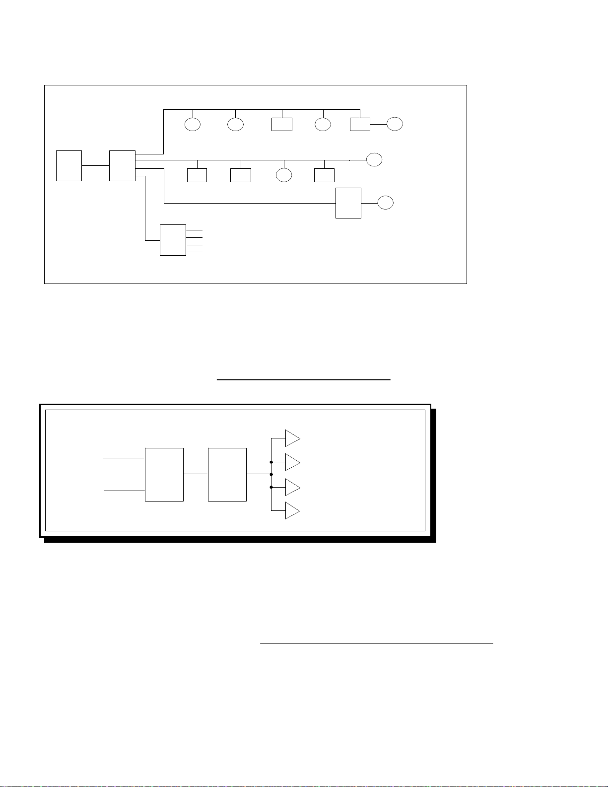
Power
Input
DMX512
input DMX512
outputs 1 ~ 4
Power
LED Active LED
(data indicator)

Terminate
Terminate
Terminate
DMX512 Devices
DMX512 Devices
House
Dimmer
Adds 4
additional
outputs
DMX512
Lighting
Console DSI-4
DSI-4
1 x 4
splitter
1 x 4
splitter
Configuration Example
PCB BLOCK DIAGRAM
Input
Resistance Optical
Isolation IC 5
Output
IC’s 1 - 4
DSI-4 Block
Diagram
Pin 2 - Data -
Pin 3 - Data +
Pin 1 - Power
Supply Common
Pin 1 -
open
Pin 2 -
Data -
Pin 3 -
Data +
INPUT: The input stage has a 68 ohm resistor in series with pin 2 and a 68 ohm resistor in series with pin 3
connecting to the input of IC #5(Optically isolated input IC). There is a 2.2K ohm resistor and the front
panel LED(data indicator LED)in parallel to the input of IC 5.
OUTPUT: The output of IC #5, sources IC #’s 1 ~ 4 that supplies data to the output connectors 1 ~ 4. Pins 1 of
each of the output connectors are tied to the power supply common.
for more information about DMX512 visit - http://www.usitt.org/standards/DMX512.html
4
DSI_4 Users Manual r3.lwp
copyright
©
2009, 2010, 2011 ELM V. T. Inc.

SERVICING
FIELD SERVICE: For Experienced Technicians
Disconnect all power and data connections. Remove the 5 face plate mounting screws on the PCB side. Use
only direct replacement parts and use static discharge precautions.
To replace an IC, using a small flat screwdriver carefully remove the IC by gently lifting up between the socket and the IC
keeping the IC as flat as possible. Bend the replacement IC’s legs so they are pointing straight down and not angled
outward. Align each pin In the center of each pin hole and gently snap into place, all legs at one time, DO NOT insert at an
angle. Insure the IC is flush on the socket with all pins.
TROUBLESHOOTING
Ÿ
check if power is present via the power LED, if
not check the internal fuse.
Ÿ
check if the input has aDMX512 signal by
bypassing theDSI-4, if not check theDMX512
console or source.
Ÿ
If the data and power areo.k. replace the input
IC and possibly the output IC’s.
Ÿ
If all outputs don’t work
Ÿ
replace the respective output IC (i.e. output
doesn’t work 4 replace IC # 4).
Ÿ
If any one of the outputs don’t work and the
other do
Ÿ
check fuse and power connections
Ÿ
Unit won’t power up
CHECK
PROBLEM
5
DSI_4 Users Manual r3.lwp
copyright
©
2009, 2010, 2011 ELM V. T. Inc.
Note - Take care not to touch the component pins or the inner pins of the connectors. Electrostatic discharge may
cause permanent damage to the unit.
5x20mm
Fuse
Optical
Input IC
4 Ouput IC’s
Face Plate
Screws

SPECIFICATIONS
CHASSIS: Anodized Aluminum .093" thick RoHS compliant.
POWER INPUT: +5VDC regulated 5%, 5.5 x 2.1 x 9.5 connector - center positive
FUSE: .7 ~ 1 Amp Fast Acting 5 X 20 mm
POWER: Apx .35 Amps with 4 outputs sourcing 32 loads each
DATA TYPE: DMX512 (250Khz)
DATA INPUT: DMX512 - 5 (or 3) pin male XLR,
Pin 1 - (Shield) Not connected, Pin 2 Data - ,
Pin 3 Data +,optically isolated from the outputs
DATA OUTPUT: 4 separate DMX512 outputs - 5 (or 3) pin female XLR's,
Pin 1 - Power supply
common, Pin 2 Data -, Pin 3 Data +
Dimensions: 3.7 x 6.7 x 2.1 inches
Weight: 1.5 pounds
6
DSI_4 Users Manual r3.lwp
copyright
©
2009, 2010, 2011 ELM V. T. Inc.
This manual suits for next models
1
Table of contents
Other ELM Video Media Converter manuals
Popular Media Converter manuals by other brands

Transition Networks
Transition Networks C4TEF1011-110 user guide

Comrex
Comrex BRIC-Link II quick start guide

GoMax Electronics
GoMax Electronics MX-3004F user manual

Digital Video Lab
Digital Video Lab Processor 8ASI/DVB-S2 RF user manual

Kramer
Kramer PT-871/2xr-KIT quick start guide

Kramer
Kramer FC-69 quick start guide