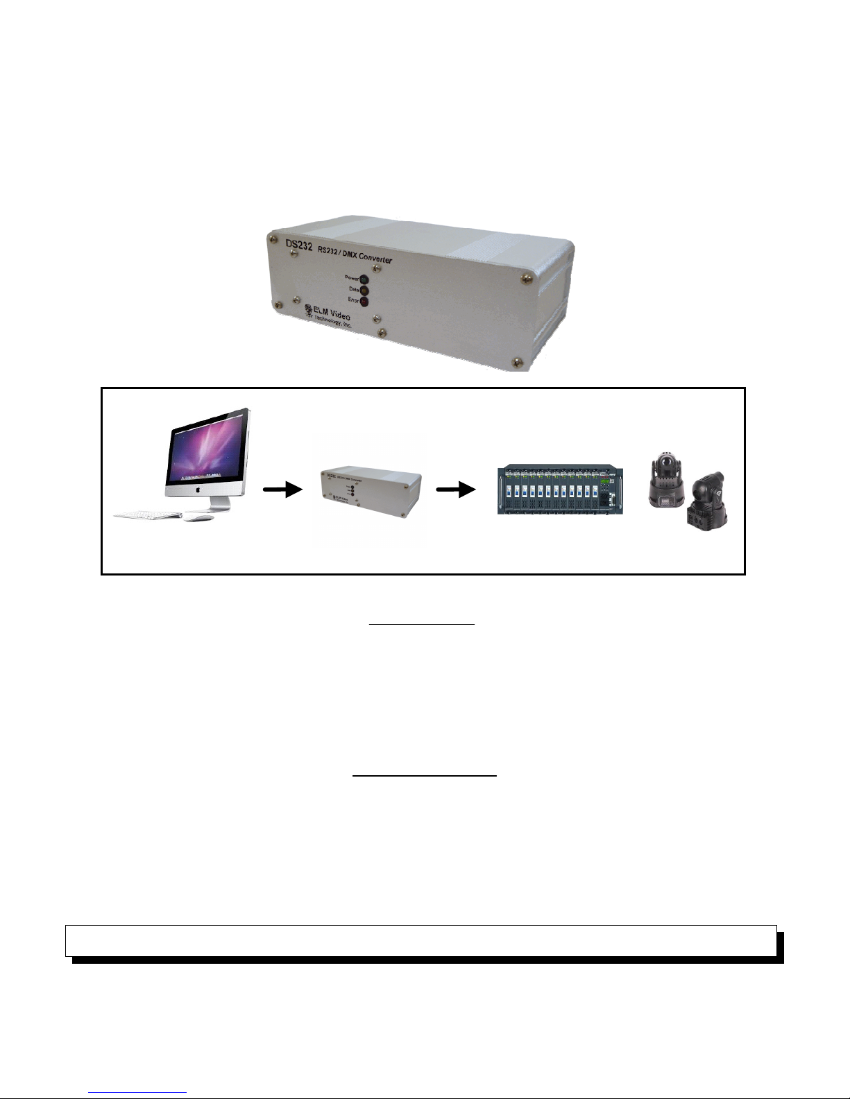
ELM Video DS232 User manual

DS232
RS232 to DMX Converter
OVERVIEW
The DS232 is an RS232 to DMX controller/driver. Connect an RS232 terminal or computer port to the DS232 unit
and drive 256 channels of DMX controlled dimmers and devices. set of commands and auto fade rates offer power
and flexibility for controlling DMX equipment. Use any RS232 terminal application to create command strings to: turn
on, off, fade up, and fade down dimmer channels. Or set a single channel or range (or a multiple set) of channels to a
specific value, and add or subtract values to existing levels. ny of the command strings can have a fade rate up to
59.9 seconds, and all 256 dimmer channels can have an independent and simultaneous fade rate up or down. With the
global fade rate command, any existing fades can be updated to a new rate, finalize, or to immediately end any fades.
CONNECTIONS
Connect an RS232 serial output device to the DS232’s RS232 input connector using a standard 9 pin male to
female through cable. Connect the DMX(512) controlled device(s) to the XLR output. If the DS232 unit is equipped with
both 3 and 5 pin XLR connectors - SE ONLY ONE OF THE O TP T XLR CONNECTORS. The ‘data’ LED will blink
when an RS232 character is received. The ‘error’ LED will illuminate solid if an invalid character, or if an invalid string
character is received. blinking ‘error’ LED indicates an internal DMX transmission or RS232 overrun error has
occurred and input data commands could have been lost. Both errors can be cleared with a power reset, ‘R’ or ‘C’
command. Insure that the DMX512 daisy chain is terminated at the end device, up to a maximum of 32 devices, and
never ‘T’ a DMX daisy chain.
Note - If the DS232 unit is equipped with both 3 and 5 pin DMX output connectors - use only one.
RS232
DMX Device: Dimmers, Moving Heads,
LED Pars
,
Splitters
,
Relays
,
etc
.
ELM Video Technology’s
RS232 to DMX
Converter / Controller
RS232 Source

OPERATION
Once powered the DS232 will immediately send a DMX signal (256 channels). To control the dimmer channel
values, send command strings from a serial terminal application. The command string can contain up to 96 characters
and must be entered with the proper syntax (shown below). n error will occur (indicated by a solid red LED) if an
invalid character is entered or a character in the incorrect order within a string. Each command string is not executed
until the ‘G command is sent.
If a fade rate (up or down) is desired any command string can end with a fade command and all the dimmer
channels included in the string will fade to the intended value at the fade rate from their current value(s). ll 256
dimmer channels can have simultaneous and independent fade times up or down. global fade rate command can be
sent that will override any existing fades to a new value to lengthen, shorten, or end fades. The fade command must be
entered in the range of F00.0 through F59.9 seconds.
The default dimmer channel values are entered as percentage values in the range of 0 to 100%. If specific
values are needed, the input level mode can be changed by setting the NON VOL TILE memory setting by sending a
mode change of “M=L”. When a mode change is received the red LED will flash indicating the mode change is stored.
(Re power if desired to verify the mode change.) This will allow dimmer channel values in commands and string of
commands to be entered in the range of 0-255. NOTE - This is a non volatile memory setting, a power reset or loss will
not change this setting. It is recommended to initially setup the unit in the desired mode. DO NOT R N PROGRAMS
THAT WILL CHANGE THIS SETTING (as non volatile memory has a limited number of changes - see specs).
Command Characters ccepted:
0-9, C, D, F, G, L, M, R, @, <, >, =, +, -, ., %, space, LF (line feed), and CR (carriage return)
Character Definitions:
‘0-9’ numeric values
‘D’ is the ‘Dimmer’ command - any dimmer range commanded start with ‘D’
‘F’ a Fade command string can optionally end with a fade command, or can be entered independently followed with a
ny existing fades on any channel(s) will be overridden with any new command string with fade rate or global fade rate
command. The new fade rate is calculated from the existing channel level at the time the new fade rate is received.
Each dimmer (256) can have an independent fade rate in either direction (up or down) with an accuracy of -250mS.
‘M’, ‘L’, and ‘%’ - (Mode, Level, Percentage) used to change the level entry type of % or ‘L’ Level. Send independently
(not within a string). ‘M=L’ sets the level mode - dimmer channel levels will be interpreted as specific level values in the
range of 0-255. ‘M=%’ sets the level mode to percentage - dimmer channel levels will be interpreted as percentage
values in the range of 0-100%. NOTE - This is a non volatile memory setting, a power reset or loss will not change this
setting. It is recommended to initially setup the unit in the desired mode. DO NOT R N PROGRAMS THAT WILL
CHANGE THIS SETTING (as non volatile memory has a limited number of writes - see specs).
‘C’ [single command ] Clear command - clears any existing errors and does not effect dimmer levels
‘G’ [single command ] Go or execute command - used to execute a string or global fade command
‘R’ [single command ] Reset command - will clear all errors and set all channel levels to zero
‘space’, ‘LF’ (line feed), and ‘CR’ (carriage return) are ignored (nor stored) and won’t generate an error
Command Ranges:
‘+’ is an ‘and’ range e.g. D5+127+201, commands dimmers 5 and 127 and 201
‘- ‘ is a 'through' range e.g. D37-50, commands dimmers 37 through 50.
Note - with the through range command the channel values must be in the range of 1
through 256 and 1st channel must be less in value than the 2nd channel.
Command ctions:
‘@’ sets the dimmer range to the level commanded e.g. D10@55, commands dimmer 10 to go to 55% (string fade time
optional) Note - If a string commands a duplicate channel or range of channels within the same string - the 1st segment
of the string overrides the latter value(s) within the string.
‘’ is the ‘increase’ action and will increase a dimmer channel(s) by a specified level up to 100%, e.g. (current dimmer
12 is at 50%) D12<10 will increase dimmer 12 to 60% (string fade time optional).
DS232 USER GUIDE
S232 to DMX Converter
ELM Video
Technology
“Innovative DMX and MIDI Products”
Pg 2
DS232_User_Guide 4.lwp V1.00
www.elmvideotechnology.com
copyright
©
2014-2016 ELM Video Technology, Inc.

‘>’ is the ‘decrease’ action and will decrease a dimmer channel(s) by a specified level down to 0%, e.g. (current dimmer
7 is at 42%) D7>15 will decrease dimmer 7 to 27% (string fade time optional).
Note - For the ’<’ and ‘>’ actions - if a *segment within a string commands a duplicate channel or range of channels in
another segment within the same string, the values are accumulated one at a time from latest to earliest e.g. if dimmer
5 is at 50% and the following command string is sent [D2-6<10D2+5+10>2%] then dimmer 5 would 1st decrease by 2%
equaling 48% then the 1st segment of the string will increase the value by 10% for a final value of 58%.
Command String:
The command string length can be up to 96 characters and all will execute when the ‘G’ command is sent. Duplicate
dimmer channel segments are allowed within a string and all are executed from last to first. For an ‘@’ action the
earliest segment will be the final result. For the ‘<’ and ‘>’ actions, each segment will be calculated latest to earliest.
*see example below. NOTE-Wait a minimum of 100mS between strings to allow the unit time to calculate the previous
string. If a string is sent to quickly an overrun error will occur indicated by the red LED blinking.
NOTE - Wait a minimum of 10-100mS between strings to allow the unit time to calculate the previous string,
otherwise an OVERR N error will occur.
Command String Examples:
D52@95 [Dimmer 52 is prepared for 95%]
G [Go - command string is executed i.e. dimmer 52 is then set to 95%]
D20+45+99@50G [Dimmers 20, 45, and 99 are immediately set to 50%]
D100-256@10G [Dimmers 100 through 256 are immediately set to 10%]
[email protected] [Dimmer 2 will fade to 75% (from it’s current value) in 1.5 seconds]
D2+4+256<10D5-10>50G [Dimmers 2, 4, and 256 will increase by 10%, dimmers 5 through 10 will decrease by
50%, both from their current value at the time the ‘G’ command is sent]
**D10+42+50<10D40-44>5G [Dimmers 40 through 44 are increased by 5%, and then dimmers 10, 42, and 50 are
decreased by 10%.] Note - Dimmer 42 is executed in both segments, the latter is executed 1st and will be decreased
by 5% and then be increased by 10% so the final result will be an increase of 5%. *Segments within a string are
executed from last to first.
[email protected] [Dimmer 5 will fade to 10% in 10.5 seconds.]
D3+1+100<10D5-10>[email protected] [Dimmers 3, 1, and 100 will fade increase by 10%, dimmers 5-10 will
fade decrease by 50%, dimmers 105 through 110 will fade to 5%, in 59.9 seconds from their current values.] During
this fade time if a new command string is received commanding any of these dimmer channels with a fade rate, the
new fade time will override the existing fade values. For example, if at 30 seconds of this fade, dimmer 3 is currently at
5% and increasing, and a new command [email protected] is sent then dimmer 3 will now fade to 50% in 1 second from
5%.
[email protected] [Dimmers 77 through 100 will fade to 99% in 50 seconds, if at 30 seconds of this fade a
command string of D78+80@10G is sent then dimmers 78 and 80 will immediately go to 10% and the fade will be
option will be turned off for these two channels, the remaining channels 77, 79, and 81 through 100 will continue fading
as commanded.
DS232 USER GUIDE
S232 to DMX Converter
ELM Video
Technology
“Innovative DMX and MIDI Products”
Pg 3
DS232_User_Guide 4.lwp V1.00
www.elmvideotechnology.com
copyright
©
2014-2016 ELM Video Technology, Inc.

F10.0G [If an independent fade rate is sent followed by the G command, all if any existing fades will now recalculate
and fade from their existing level values at the time the command was sent to go to their intended values in 10
seconds.]
F00.0G [If an independent fade rate of 0 is sent, all if any existing fades will terminate and the respective dimmer
values will immediately go to their intended values.]
***M=L [Level mode is set] ll channel level values must be entered in a range from 0-255. For example
D2+4+10@200G, will set dimmers 2, 4, and 10 to a specific value of 200.
***M=% [Percentage mode is set] ll channel level values must be entered in a range from 0-100.
***NOTE - This is a non volatile memory setting, a power reset or loss will not change this setting. It is recommended to
initially setup the unit in the desired mode. DO NOT R N PROGRAMS THAT WILL CHANGE THIS SETTING (as non
volatile memory has a limited number of writes - see specs).
*SEGMENT - Multiple portions of a command string are composed of segments e.g. “D2@50”
DS232 USER GUIDE
S232 to DMX Converter
ELM Video
Technology
“Innovative DMX and MIDI Products”
Pg 4
DS232_User_Guide 4.lwp V1.00
www.elmvideotechnology.com
copyright
©
2014-2016 ELM Video Technology, Inc.

SPECIFICATIONS
DMX CONTROL W RNING: NEVER use DMX data devices where human safety must be maintained.
NEVER use DMX data devices for pyrotechnics or similar controls.
Manufacturer: ELM Video Technology, Inc.
Description: RS232 to DMX Converter
Ext. P/S Model Number: DS232-5V3/5P
5V Version UPC: 616453087958
Functional description: The DS232 is an RS232 (terminal or computer port) to DMX converter that will
control and drive DMX controlled dimmers and devices.
Operating temperature: 32°F to 100°F
Storage temperature: 0°F to 120°F
Humidity: Noncondensing
Non-Volatile Memory Writes: Minimum 100K, Typical 1M
Non-Volatile Memory Retention: Minimum 40 Yrs, Typical 100 Yrs
Chassis: nodized luminum .093" thick RoHS compliant.
5V Current: apx 115m - under full DMX load (60m )
RS232 Input: 9 Pin female serial connector at 9600 Baud rate, 8, 1, None
se a 9 pin male straight through cable
Command String Length:
96 characters
Command String Execute Timing:
100mS recommended
Data Output: DMX512 output 250 kHz, 5 and/or 3 pin female XLR
Pin 1 - Power supply common, Pin 2 Data -, Pin 3 Data +
Dimensions: 3.7 x 6.7 x 2.1 inches
Weight: 1.5 pounds
Internal Fuse: RS232 Converter PCB - 500m PCB mount through hole
External Power Supply: +5VDC wall mount
Voltage Input: 100 ~ 132 (or 240) V C
Current Output: 1 Typical
Power: 5 Watts Typical
Polarization: Positive Center
Output Connector: Barrel Plug, 2.5mm I.D. x 5.5mm O.D. x 9.5mm
DS232 USER GUIDE
S232 to DMX Converter
ELM Video
Technology
“Innovative DMX and MIDI Products”
Pg 5
DS232_User_Guide 4.lwp V1.00
www.elmvideotechnology.com
copyright
©
2014-2016 ELM Video Technology, Inc.
Table of contents
Other ELM Video Media Converter manuals
Popular Media Converter manuals by other brands

Sensata
Sensata E-100 user guide

TR-Electronic
TR-Electronic COV58M-65536/4096 PROFIBUS 36ZB10FL Assembly instructions

Analytic Systems
Analytic Systems VTC805MW Installation & operation manual

Orbit Merret
Orbit Merret OMX 311UNI manual

TR-Electronic
TR-Electronic CEW582M 8192 EPN Series Assembly instructions

ADF Web
ADF Web HD674-A002 user manual