ELMED ISOTEST 4S User manual

Operation manual ISOTEST 4S / 4Splus Page 1
TABLE OF CONTENTS
Product description.............................................................3
1. Proper Use ........................................................................................3
2. Design................................................................................................4
3. Functional description.....................................................................6
4. Technical data...................................................................................8
5. Performance characteristics...........................................................9
EC Conformity Declaration...............................................10
General safety information ...............................................11
1. User's Responsibility.....................................................................11
2. Explanation of safety symbols being used in this manual........12
3. Basic safety measures...................................................................13
4. Operator requirements ..................................................................14
5. Special hazards ..............................................................................15
Grounding ..........................................................................16
1. Direct grounding.............................................................................16
2. Special grounding methods..........................................................18
Testing plastic material .................................................................18
3. Indirect grounding through the soil .............................................19
4. Capacitive grounding.....................................................................19
Safety button......................................................................22
1. Functional description of the single-stage safety button
(standard version)..............................................................................22
2. Function of the double-stage safety button (optional version).22
Startup................................................................................25

Page 2 Operation manual ISOTEST 4S / 4Splus
Check the settings and modify, if required..................... 27
1. Turn the ISOTEST®test equipment on......................................... 28
2. Operating mode of the safety button...........................................28
3. Filter settings..................................................................................28
Changing the operating mode of the safety button ....... 29
Changing Filter Settings................................................... 29
Error messages and troubleshooting (Checklist) .......... 30
Repair................................................................................. 33
1. Storage............................................................................................33
2. Maintenance.................................................................................... 33
3. Inspections/Calibration .................................................................33
4. Repairs ............................................................................................ 34
Additional information...................................................... 35
1. Definitions of terms .......................................................................35
2. Rechargeable battery.....................................................................38
3. Battery chargers............................................................................. 38
4. Extension bars................................................................................ 42
Overview of controls......................................................... 44

Operation manual ISOTEST 4S / 4Splus Page 3
Product description
1. Proper Use
ELMED ISOTEST®test equipment has been exclusively designed for
mobile testing of non-porosity of non-conducting or semiconducting
materials, especially insulation, and may only be used for this purpose.
-The equipment is not designed to be used for the stationary
continuous operation.
-Other use than described above is prohibited.
Please note that
operating the equipment in explosion-hazard environments is
strictly forbidden.
Proper use extends on reading these operating instructions as well as
meeting all relevant requirements, especially safety regulations.
Furthermore, all inspection and maintenance should be performed within
the specified time intervals.
During the operation of ISOTEST®test equipment, radio equipment
or radio services may be affected by radio interference. In these
cases, the equipment must not be used. The equipment should
always be turned on only for a minimum period of time.
ISOTEST®test equipment may only be operated by trained personnel.
If ISOTEST®test equipment is not used as described above, safe
operation cannot be guaranteed.
The manufacturer does not assume any liability for injuries of persons or
damage to equipment if the test equipment is not properly used.
These operating instructions apply to all units of the following series:
ISOTEST 4S and 4Splus

Page 4 Operation manual ISOTEST 4S / 4Splus
2. Design
All ELMED ISOTEST®test equipment is designed for maximum safety.
The units are designed and manufactured according to acknowledged
safety rules and the current state of art.
The high safety standards guarantee that personal is protected from
electric shock hazards. Potential hazards resulting from pulse
voltages in the ISOTEST®are clearly below the allowable limits of
IEC 479-1 and IEC 479-2.
The basic construction of all ISOTEST®test equipment is very similar with
respect to the components being used:
Enclosures Rugged polystyrene enclosure with
separate compartment for
rechargeable batteries
Carrying Case A leather carrying case with
shoulder and carrying belt as well
as transparent pouch with user
guide
Power Supply Easily replaceable lead-acid
accumulator (maintenance-free)
Lithium battery
Deep discharge protection of
rechargeable battery Acoustic alarm by piezo buzzer
when the operating voltage falls
below its allowable minimum plus
warning indication by LED and
automatic partial shut-off after 1
minute
Operation Rotary Switches
Voltage Generation (test voltage) Processor-controlled switching
power supply with high-voltage
transformer
Adjustable Test Voltage (with limits) Spherical spark gap with stepping-
motor control and continuous zero
calibration or electronic spark gap
Adjustable Test Voltage Rotary Switches
Indication Of Test Voltage Values on membrane-switch front
panel
Operation manual ISOTEST 4S / 4Splus Page 5
Test Voltage Regulation Load-dependent, processor-
controlled electronic adjustment
(continuous)
Load Matching Freely selectable filter adjustment
for optimum matching to individual
test conditions
Adjustable Load Matching Rotary Switches
Evaluation Of Voids Integral Evaluation Process
Void Indication
Acoustic by piezo buzzer, visual by
LED
Safety Button (single-stage) Switch-on of test voltage
Safety Button (double-stage)
(optional)* Switch-on of test voltage
Selectable emergency shut-down
funkction
Maintenance LED Indicators
Maintenance and repair of the test equipment may only be
performed by qualified personnel authorized by ELMED.
Special care should be taken when opening the unit because
metal parts may become accessible that carry voltages
considerably higher than the unit's supply voltage.
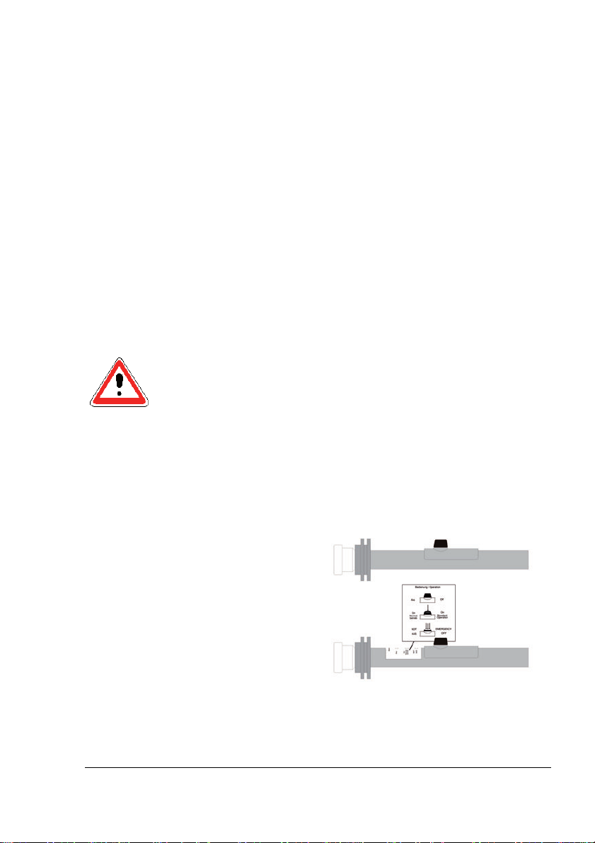
* Holiday detectors – optionally equipped with the double-stage
safety button - are marked with an instruction plate above the
safety button on the handle
Safety Button (single-stage)
Safety Button (double-stage)

Page 6 Operation manual ISOTEST 4S / 4Splus
3. Functional description
By using a high-voltage tester, even the smallest voids can safely be
detected. Voids can be pinholes, cracks or weak spots.
Depending on the grounding method employed, the following tests can be
performed:
Recognition of voids in non-conducting or semiconducting coatings
on electrically conductive carrier material.
Areas of application, e.g.,:
Systems for protection of pipelines
Coatings applied by the
manufacturer
(internal and external)
Coatings applied in the field
Tanks and containers
Coating material, e.g.:
Polyethylene (PE)
Bitumen
Butyl rubber bands
Petroleum jelly
Gummings
Rilsan
Halar
Ceramic
Enamel
Epoxy resin
Powder coatings
Carrier material, e.g.:
Fe-based metals
Ne-based metals
Electrically conductive fillers
Electrically conductive fleece
Concrete with sufficient residual
moisture
Before testing, the test object as well as the ISOTEST®test equipment
must be grounded.
Subsequently, a suitable testing electrode is moved in close distance to
the test object across the latter's entire surface. The test voltage applied
to the testing electrode should be chosen according to the coating
thickness as well as the relevant standards and manufacturer
specifications.

Operation manual ISOTEST 4S / 4Splus Page 7
A void is detected by sparking between the testing electrodes and the
electrically conductive carrier material as well as an acoustic and visual
alarm.
Voids and porosity with or without inclusions can be detected in
non-conducting material such as welded or glued seams.
Material types, e.g. All types of plastic
Ceramic
Manufacturing types, e.g. Foils
Plates
Enclosures
Pipelines
Hoses
The test object and the ISOTEST®test equipment are grounded by
applying the suitable coating of electrically conductive material.
Subsequently, a suitable testing electrode is moved in close distance to
the test object across the latter's entire surface. The test voltage applied
to the testing electrode is to be chosen according to the coating thickness
as well as the relevant standards and manufacturer specifications. A void
can be detected by sparking between the testing electrode and the
electrically conductive ground electrode, and is indicated by an acoustic
signal and a red LED on the membrane-switch front panel.
Among others, the following grounding methods can be applied:
Applying electrically conductive foils and fleeces
Applying electrically conductive rubber mats
Filling with electrically conductive liquids or solid matters
Insertion of a metal wire
Missing or marginal grounding of the ISOTEST®test equipment
and/or test object may result in accidents and injury to persons.
Chapter "Grounding" contains a detailed description of all
possible grounding methods.

Page 8 Operation manual ISOTEST 4S / 4Splus
4. Technical data
Power Supply
Supply Voltage Lead-acid accumulator, 6 V/4.5 Ah,
with integrated fuse, connecting
cable and two-prong safety plug *
Lithium battery
Current consumption (load-
dependent) Approx. 0.8 A (2.0 A maximum)
Test duration (cycle operation) Approx. 9 h
Test duration (continuous
operation) 2.5 to 5.5 h
Test voltage
Magnitude of test
voltage ISOTEST
ISOTEST
4S : adjustable in 4 steps from
10 to 25 kV in steps of 5 kV
4Splus: adjustable in 7 steps in the
range of 5 to 35 kV
Signal shape Unipolar high-voltage pulses
Cycle duration Approx. 10 µs
Pulse repetition frequency 25 Hz
Current (rms) Approx. 40 mA
Dimensions and weights
(complete unit, including carrying
case)
Length 280 mm
Height 230 mm
Width 120 mm
Length of high-voltage cable 1500 mm
Weight, including handle 4.5 kg
Weight of rechargeable battery 0.9 kg
Type of protection IP 42
Ambient temperature limit: -10oC to +50oC
(Heat timing constant: > 10 K/h)
* To avoid fire hazards and damage to the rechargeable battery, the
pins of the safety plug must not be shorted under all circumstances.
Even shorting these pins over a short period of time may cause the
fuse to blow and prevent from testing the charge state.
To ensure proper safety and functionality of the rechargeable battery,
defective fuses may only be replaced with original fuses.

Operation manual ISOTEST 4S / 4Splus Page 9
5. Performance characteristics
ISOTEST®test equipment excel with the following features:
Maximum safety of personnel by fiber optic controlled safety button
and ground connection monitoring
Significantly reduced hazards for personnel by pulse-shaped test
voltage and processor-controlled, load-dependent supply voltage
regulation
The processor-controlled, load-dependent supply voltage regulation
guarantees a constant test voltage even under worst-case load
conditions
The test voltage is adjusted using a self-calibrating spherical spark
gap according to VDE 0433 or an electronic spark gap
The high pulse repetition frequency allows testing speeds of up to
300 mm/s
By making use of extremely short, unipolar high-voltage pulses and a
specially designed evaluation circuitry, even the smallest pinholes
(channels) and voids can be detected and indicated with only a
minimum of material stress
Residual electrostatic charge on the test object is negligible if the
tests are performed correctly
Pinhole and leakage tests of non-conducting or semiconducting
materials
Testing of completely coated test objects by making use of capacitive
grounding
All ISOTEST®test equipment carries the CE label and meets the
requirements of all relevant standards and specifications
(DIN EN/ISO, DVGW, etc.)

Page 10 Operation manual ISOTEST 4S / 4Splus
EC Conformity Declaration
It is herewith confirmed that the products listed below
ISOTEST 4S
ISOTEST 4S plus
meet the safety requirements within the scope of the conformity evaluation procedure of the
related competent authority, which are defined in the regulation 2004/108/EG of the European
Council for the approximation of laws of the member states with respect to electromagnetic
compatibility. The same applies to the provisions of the law on electromagnetic compatibility of
electrical equipment (EMVG) as of 9 November 1992.
This declaration applies to all units that are manufactured in accordance with the appropriate
manufacturing documentation which is part of this declaration.
For the evaluation of products regarding the electromagnetic compatibility, relevant
harmonized standards have been used.
Immunity: EN 61000-6-2:2005 including:
EN 61000-4-2:2009; EN61000-4-3:2006 + A1:2008
IEC 61000-4-2:2008
IEC 61000-4-3:2006 + A1:2007
Emission: EN 55011:2009 (IEC/CISPR 11:2009 modified)
The devices meet the requirements of class A in the standby mode and are designed for
operation in industrial environments. In occurrence of radio interference while using the
devices in residential or commercial areas, the use must be kept as short as possible or the
device must be switched off.
Design-engineering modifications that have such significant effects on both the
technical specifications and the proper use defined in this operation manual so as to
change the instrument significantly shall nullify this declaration of conformity.
This declaration has been signed for manufacturer
ELMED Dr. Ing. Mense GmbH, Heiligenhaus
by
Claudia Mense
Managing director
Heiligenhaus, 14th February 2012

Operation manual ISOTEST 4S / 4Splus Page 11
General safety information
1. User's Responsibility
All ISOTEST®test equipment has been designed and manufactured,
considering hazard analyses and compliance with the relevant
harmonized standards as well as additional technical specifications.
Therefore, ISOTEST®test equipment is state-of-the-art equipment and
offers a maximum of safety.
However, this safety level can only be achieved if all required measures
have been taken. The user of the test equipment is responsible for
planning and performing these measures and for verifying their proper
execution.
The user is especially responsible for ensuring that
-ISOTEST®test equipment is only used as intended by the
manufacturer (please refer to Chapter "Product Description"),
-the test equipment is only operated if in perfect condition,
-required personal protective equipment is available and being used,
-the operating instructions are always legible and available at the
workplaces where the test equipment is used,
-the test equipment is only operated by qualified and authorized
personnel,
-this personnel is trained in all aspects of industrial safety and
environmental protection, and knows the contents of the operating
instructions and the relevant safety regulations,
-no safety labels are removed from the equipment and that all safety
labels are clearly legible.

Page 12 Operation manual ISOTEST 4S / 4Splus
2. Explanation of safety symbols being used in this manual
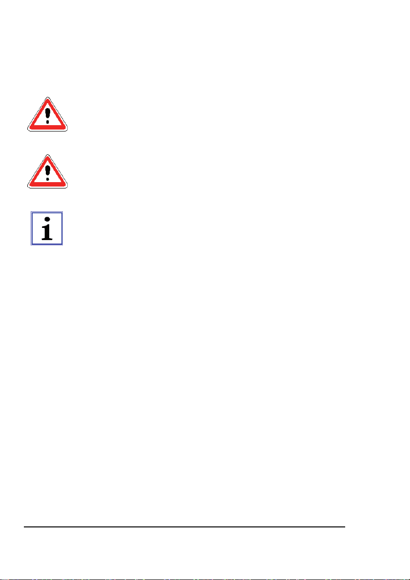
The following symbols are used in these operating instructions:
Safety symbols indicate the presence of adjacent safety notes.
Special symbols indicate important information that should strictly be
observed.
This symbol indicates that the relevant action imposes a hazard for life
and limb.
Danger
The symbol indicates information provided for improving the
understanding of processes.
NOTE

Operation manual ISOTEST 4S / 4Splus Page 13
3. Basic safety measures
The basic safety guidelines and regulations of the relevant professional
associations apply.
Before turning on the ISOTEST®test equipment, the workplace should be
checked for potential obstacles and safety hazards, e.g., tripping hazards.
Intentional or inadvertent touching of a metal part possibly carrying high
voltage and an uncontrolled action resulting from this electric shock must
not lead to hazard for personnel. This also applies to working on ladders
and scaffolds.
Before insertion or removal of testing electrodes, the ISOTEST®test
equipment must be turned off using the main switch.
After turning on the unit with the main switch, the area behind the red
insulator (electrode clamping device) as well as the testing electrode in
the handle must not be touched.
During the tests, suitable work clothes and shoes meeting the
requirements of industrial safety regulations should be worn.
If tests are performed in small rooms or containers, the relevant safety
regulations and guidelines must be observed
(e.g., safety guards).
High-voltage sparks lead to the formation of ozone. To avoid excessive
ozone concentrations in rooms or containers, sufficient ventilation must
be provided.
Special care should be taken when using high-voltage extension cords or
extension bars as this will tamper safety shielding against accidental
contact with hazardous live adjacent to the electrode clamping device.
When using circular electrodes for testing the inner side of cylindrical
parts, the ISOTEST®test equipment must be turned off during insertion or
removal of the electrode.

Page 14 Operation manual ISOTEST 4S / 4Splus
By using suitable testing electrodes, a test method should be available
that avoids touching of the testing electrodes during the tests.
To maintain the high safety standards, only original ELMED accessories
such as testing electrodes may be used.
4. Operator requirements
ISOTEST®test equipment must not be used by unqualified or
unauthorized personnel. Persons who intend to operate the test
equipment must have read the operating instructions, especially Chapter
"Safety Information", and observe these instructions.
These persons must have been trained in the basic regulations on
industrial safety and accident prevention.
Operating personal still being in the training phase must not operate the
ISOTEST®test equipment unless supervised by a sufficiently trained
person.
A certificate of a successfully completed training course is required.
Operation manual ISOTEST 4S / 4Splus Page 15
5. Special hazards
Important notice for wearers of a
Heart pacemaker
During operation of the ISOTEST®unit it is necessary to take into
consideration a fault in the form of switching over of the heart
pacemaker into error mode. It is possible to avoid this effect on heart
pacemakers by ensuring that patients with implanted pacemakers do
not get closer than 3 m to
the test unit and the spark gap
the test electrodes
the test object being tested and all parts connected to it electrically
and the earthing cable.
Patients with pacemakers must not use this insulation testing
equipment!!
Excerpt from the expert opinion of 20.02.1997
Important advice for epileptics
Contact with high voltage or parts which conduct high voltage could lead
to epileptic attacks if you are accordingly susceptible to them.
Page 16 Operation manual ISOTEST 4S / 4Splus
Grounding
To enable safe porosity tests with high voltage, both the ISOTEST®test
equipment and the test object shall be grounded.
Independently of the grounding method, all electrical
connections should exhibit the lowest resistance possible.
The contact surfaces for attaching the clamping tongs should
be free from contamination and stain.
To prevent inadvertent pulling of the grounding plug from the
ISOTEST®test equipment, the stress relief attached to all
grounding cables should be hooked to the snap link at the bag.
When describing the grounding methods, basically both the
grounding of the ISOTEST®test equipment and the test object
described.
Depending on the test assignment, the following grounding methods can
be employed.
1. Direct grounding
Direct grounding is used when the grounding conductor can be
connected to a contact surface free from contamination and stain.
Required accessories:
Standard grounding cable with plug and clamping tongsPart number:
0174320000 (supplied)
Grounding cable, length of 15 m, with plug and clamping tongs Part
number: 0174200100
Application:
1. Connect the plug of the standard grounding cable to the grounding
receptacle of the ISOTEST®test equipment.
Connect the clamping tongs at the other end of the grounding cable
to the test object.
2. Connect a pair of clamping tongs of the second grounding cable (part
number 0174200100) to the test object.
Connect the second pair of clamping tongs to a ground terminal.
3. Turn the ISOTEST®test equipment on and perform the high-voltage
test.

Operation manual ISOTEST 4S / 4Splus Page 17
alternatively
Required accessories:
Grounding cable Y - type (clamping tongs - clamping tongs/plug)
Part number 0174250010
Application:
1. Connect the plug of the Y grounding cable to the grounding
receptacle of the ISOTEST®test equipment.
2. Connect the clamping tongs at the other end of the grounding cable
to the test object.
Connect the second pair of clamping tongs to a ground terminal.
3. Turn the ISOTEST®test equipment on and perform the high-voltage
test.
alternatively
Required accessories:
Standard grounding cable with plug and clamping tongs
Part number: 0174320000
(supplied)
Grounding stick with cable, 2 m Part number 0174200000
Application:
1. Connect the plug of the standard grounding cable to the grounding
receptacle of the ISOTEST®test equipment.
Connect the clamping tongs at the other end of the grounding cable
to the test object.
2. Connect the clamping tongs at the cable from the grounding stick to
an accessible area of the test object.
3. Deeply bury the grounding stick in the soil. If the soil is dry,
thoroughly water the respective area to obtain a low-resistance
connection.
4. Turn the ISOTEST®test equipment on and perform the high-voltage
test.

Page 18 Operation manual ISOTEST 4S / 4Splus
2. Special grounding methods
Testing plastic material
In most cases, welding seams will be tested when testing plastic material.
To allow using the high-voltage test method, coat the welding seam
and/or area with a electrically conductive material (grounding electrode).
Attach a grounding electrode to the entire rear of the area to be tested.
Pinholes and voids will safely be detected by sparking between the
testing electrode and the grounding electrode.
Required accessories:
Grounding foil
Part number 0174500100
Grounding cable Y - type (clamping tongs - clamping tongs/plug)
Part number 0174250010
Application:
1. Cut the grounding foil to the required size.
Tear off the protective foil by holding at the edges, and fold one
corner. Glue the remainder of the grounding foil to the entire rear of
the welding seam or area to be tested, press against the test object,
and remove all air bubbles by wiping. Remove the protective foil step
by step.
2. Connect the plug of the Y grounding cable to the grounding
receptacle of the ISOTEST®test equipment.
3. Attach a pair of clamping tongs at the grounding cable to the folded
corner of the grounding foil, and attach the second pair of clamping
tongs to ground, ensuring a low-resistance path.
To obtain safe stress relief for the clamping tongs at the folded corner
of the grounding foil, secure the grounding foil with adhesive tape,
e.g., friction tape.
4. Turn the ISOTEST®test equipment on and perform the high-voltage
test. Remove the grounding foil after the test.
As an alternative to the grounding foil described above, you can also use
electrically conductive fleeces, grounding mats or grounding collars made
of electrically conductive rubber for testing of plastic parts.
The leakage test of containers can be performed using electrically
conductive liquids, e.g., saltwater, acids, etc.
Welding seams can also be tested by inserting a wire.
Grounding brushes are available for cylindrical test objects.

Operation manual ISOTEST 4S / 4Splus Page 19
3. Indirect grounding through the soil
Indirect grounding is used where the distance between the test object and
a suitable grounding terminal is greater than 15 m. Typical examples are
completely muffled pipelines.
Required accessories:
Trailing ground wire Part number 0174120000
Grounding stick with cable, 2 m Part number 0174200000
Application:
1. Connect the plug of the trailing ground wire to the grounding jack of
the ISOTEST®test equipment.
Spread the bronze spiral of the trailing ground wire (6.5 m) on the soil
in full length.
2. Connect the clamping tongs at the cable from the grounding stick to a
non-insulated area of the test object.
3. Deeply bury the grounding stick in the soil. If the soil is dry,
thoroughly water the respective area to obtain a low-resistance
connection.
4. Turn the ISOTEST®test equipment on and perform the high-voltage
test.
Indirect grounding can only be used if the following conditions are met:
the test object is grounded
because of its characteristics, the soil exhibits the required
conductivity
-all types of moist soil are suitable
-unsuitable are, e.g., dry sand, asphalt, and flags.
4. Capacitive grounding
Capacitive grounding is used where direct or indirect grounding is not
possible.
This is the case when the test object has metal carrier material that is
inaccessible or consists of completely coated material.

Page 20 Operation manual ISOTEST 4S / 4Splus
a) Grounding of coated test objects, using grounding collars
Commonly used test objects are pipelines that have been coated in the
field after repair and are subject to high-voltage testing.
As there is normally no possibility of direct or indirect grounding,
grounding collars offer the only possibility of proper and safe grounding.
Required accessories:
Grounding collar, type 1, for DN 100 - 200
Part number 0174401020
Grounding collar, type 2, for DN 200 - 400 (alternative)
Part number 0174402040
Grounding collar, type 3, for DN 300 - 600 (alternative)
Part number 0174403060
Grounding collar, type 4, for DN 500 - 1000 (alternative)
Part number 0174450100
Grounding stick with cable, 2 m
Part number 0174200000
Application:
1. Wrap the grounding collar tightly (without any air gaps) around the
pipe and fix it with the lashing strap. The grounding collar must be
aligned such that the two connecting bolts can be used for the
connection of the grounding cables.
2. Bury the grounding stick deeply in the soil. If the soil is dry, water the
respective area thoroughly to obtain a low-resistance connection.
3. Connect the clamping jaw on the cable of the grounding stick to one
of the connecting bolts on the grounding collar.
4. Connect the plug of the standard grounding cable to the ground jack
of the ISOTEST®test device. The clamping jaw on the other end of
the ground cable must be connected to the remaining connection bolt
of the grounding collar. The bolts must be metallic bright.
The bolts should be free from contamination and stain.
5. Switch the ISOTEST®holiday detector on and perform the high-
voltage test.
This manual suits for next models
5
Table of contents
Other ELMED Test Equipment manuals


Popular Test Equipment manuals by other brands


Metrohm
Metrohm E1612 instruction manual

Wiltron
Wiltron 560-9 Series Operation and maintenance manual

Alcohol Countermeasure Systems
Alcohol Countermeasure Systems Alcolock V3 B-2 Series instruction manual

Huazheng
Huazheng HZJY-10K-IA user manual

Intellinet
Intellinet 515566 user manual

Tietzsch
Tietzsch ZAP 1050L User instructions