ELMED HELIO-STROB micro2 User manual

Operation manual HELIO-STROB micro2 Page 1
CONTENT
GENERAL SAFETY INSTRUCTIONS ............................................. 2
1. User’s due diligence ................................................................... 2
2. Explanation of safety symbols used in this manual ............... 3
3. Special hazards .......................................................................... 4
4. Basic rules on safety precautions ............................................ 5
EC DECLARATION OF CONFORMITY .......................................... 6
PRODUCT DESCRIPTION .............................................................. 7
1. Proper use ................................................................................... 7
2. Design .......................................................................................... 7
3. Function description .................................................................. 7
4. Technical specifications ............................................................ 8
OPERATION .................................................................................... 9
1. General Information ................................................................... 9
2. Main functions .......................................................................... 10
3. Setup controls........................................................................... 11
4. Special commands ................................................................... 13
MAINTENANCE ............................................................................. 16
1. Storage ...................................................................................... 16
2. Maintenance .............................................................................. 17
3. Inspection / Calibration ............................................................ 17
4. Dispatch / Transport ................................................................. 17
5. Repairs / Disposal .................................................................... 18
ADDITIONAL INFORMATION ....................................................... 19
Definition of terms ........................................................................ 19
V. 11/2019

Page 2 Operation manual HELIO-STROB micro2
GENERAL SAFETY INSTRUCTIONS
1. User’s due diligence
The HELIO-STROB micro2 has been developed and manufactured
in consideration of hazard analysis and in compliance with the
relevant harmonised standards as well as the additional technical
specifications.
Therefore, the HELIO-STROB micro2 is a state-of-the-art instru-
ment and offers a maximum of safety. This safety can be achieved
only if all required safety precautions have been taken. Subject to
due diligence, the user of this instrument shall plan such precau-
tions and supervise their execution.
At any time it should be ensured that
every user reads all safety and operating instructions before
operating the stroboscope.
these safety and operating instructions are maintained for
future reference.
the HELIO-STROB micro2 is used according to the intended
purpose (see chapter Product description).
the instruments are operated only if in perfect, fully functional
condition.
the complete operating instructions are legible and available at
the place where the instrument is used.
the instruments are operated only by adequately qualified and
authorised personnel which is regularly trained in all aspects
related to occupational health and safety; this personnel knows
and follows the operation instructions, especially the relevant
safety regulations contained therein.
all safety and warning labels are clearly legible and non of
them are removed from the instrument.

Operation manual HELIO-STROB micro2 Page 3
2. Explanation of safety symbols used in this manual
The following symbols are used in this manual:
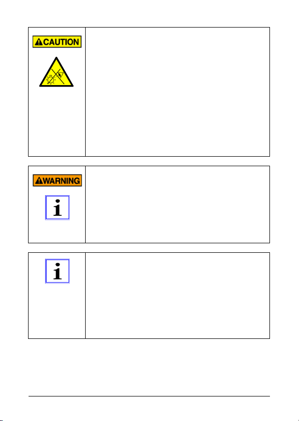
Safety symbols call attention to adjoining safety notes
(see fig. 1 – 3)
Instruction symbols indicate important information that should
be strictly observed (see fig. 4)
1. WARNING indicates a hazardous situation which, if not avoid-
ed, could result in death or serious injury.
2. CAUTION, used with the safety alert symbol, indicates a haz-
ardous situation which, if not avoided, could result in minor or
moderate injury
3. This symbol warns of exposure to optical radiation.
4. This symbol indicates information to be used for a better under-
standing of processes.

Page 4 Operation manual HELIO-STROB micro2
3. Special hazards
In case of users with a neurological prone-
ness to epileptic seizures, the light effects pro-
duced by a stroboscope may cause photoin-
duced epilepsy. Users with such predisposition
must not use stroboscopes!
Safety Guidelines for people wearing active
implants
When using stroboscopes, an influence of ac-
tive implants (e.g. pacemakers) cannot be com-
pletely excluded. For safety reasons we rec-
ommend that people wearing active implants
are excluded from working with stroboscopes.
Persons wearing active implants have expres-
sively to be instructed in this regard.
Operation manual HELIO-STROB micro2 Page 5
4. Basic rules on safety precautions
Do not look into the LED-radiation directly
and unprotected as this could be dangerous
for the eyes – especially over longer periods
of time.
Due to the dazzle effects caused by the LED
at short distances, the ability to see may be
disturbed in such manner as to make orienta-
tion impossible.
LED-radiation shall not be directed to the
eyes of other persons.
Do not use any strongly focussing optical de-
vices to look at the light beam.
Within professional organisations the employer /
entrepreneur has to inform the employees / in-
sured workers about the possible hazards relat-
ed to their work and the safety precautions to be
applied. This shall include the current findings
regarding hazard avoiding procedures and eye-
lid protective reflexes.
Ultra bright LED radiate a similar bundled light
as laser. Accordingly, the same regulations shall
apply for LED – especially for distances below
one meter – as for laser. However, due to the
general large radiation divergence and the lami-
nar source expansion, performance LED do not
have similar potential for danger as the bundled
laser radiation.
Page 6 Operation manual HELIO-STROB micro2
EC DECLARATION OF CONFORMITY
It is herewith confirmed that the product listed below
HELIO-STROB micro2
meets the safety requirements within the scope of the conformity evalua-
tion procedure of the related competent authority, which are defined in the
regulation 2004/108/EG of the European Council for the approximation of
laws of the member states with respect to electromagnetic compatibility.
The same applies to the provisions of the law on electromagnetic compat-
ibility of instruments (EMVG) as of 9 November 1992.
This declaration applies to all units that are manufactured in accordance
with the appropriate manufacturing documentation which is part of this
declaration.
For the evaluation of products regarding the electromagnetic compatibility
relevant harmonised standards have been used.
DIN EN 61000-6-1
DIN EN 61000-6-3
Design-engineering modifications that have such significant effects
on the technical specifications and the proper use defined in this
operation manual so as to change the instrument considerably shall
nullify this declaration of conformity.
This declaration shall be legally binding for the manufacturer.
ELMED Dr. Ing. Mense GmbH, Heiligenhaus
signed by
Claudia Mense
Managing Director
Heiligenhaus, 28th August 2012

Operation manual HELIO-STROB micro2 Page 7
PRODUCT DESCRIPTION
1. Proper use
The HELIO-STROB micro2 is an LED stroboscope (light flashing
instrument) for industrial applications. This instrument is used to
produce snap-shots of sequences which, due to the rapidness they
proceed, are not perceivable by the human eye.
More information on www.elmedgmbh.com
The user, not the producer, shall assume any liability related to any
personal injury or material damage resulted from the inadequate
use of the instrument.
It’s prohibited to operate the instrument in ex-
plosionhazardous environments.
2. Design
The instruments are designed and manufactured according to
acknowledged safety rules and the current state of the art.
Metal case
A
BS (UL 94 HB) RAL 9002
Power supply 2 x AA alkaline / LR6 / NiMH
Light source 3 x ultra-bright red LED (CREE)
Operation Membrane keyboard
Measured value display digital (7-segment display)
3. Function description
The HELIO-STROB micro2 provides the following functions:
phase shifting up to 360°
alternative display of Hz (fps) and RPM (fpm)
frequency selection by fast search mode (auto repeat)
frequency divider and multiplier
memory function
adjustable flash duration
external triggering

Page 8 Operation manual HELIO-STROB micro2
4. Technical specifications
Power supply 2 x AA alkaline (LR6) or
2 x AA NiMH accumulator (HR6)
Power consumption 60 – 1500 mA depending on opera-
tion mode
Metal case dimensions 140 x 62,7 x 38 (mm)
Weight 175 g
Light source 3 x ultra-bright LED (CREE)
Internal flash rate control adjustable by membrane
keyboard
External flash rate control 5 – 30 V (TTL compatible)
positive / negative flank,
adjustable
Frequency range 1 – 2000 Hz / 60 – 99999 fpm
Measured value display digital, 5-digit 7-segment display,
character height 8 mm, red
Display in fpm / Hz yes / yes
Measuring time 0,33 s (min.1 period)
Display resolution up to 0,01 fps / 0,1 fpm
Phase shifting in degrees
Degree range 0 – 360°
Degree resolution 0,1°
Special functions integral frequency multiplication /
division (on internal trigger)
automatic flash duration
adjustment or set-up
power save mode
memory function
Light intensity max. 3800 Lux (@ 50 Hz / 20 cm)
Radiation angle 19° or 42° (s. battery compartm.)
Precision 0.005 % ± 1 digit
Operating temperature 0° … +40°C
Storage temperature -20° … +60°C
A
ir humidity 80% relative air humidity at 30°C
Protection class IP40
NiMH accumulators are not to be deeply discharged.
To prevent this, the optical warning ACCU appears in
the display and the device is automatically shut off.
The same applies to standard batteries.
Operation manual HELIO-STROB micro2 Page 9
Operation
1. General Information
The functions shall be operated by pressing the keys of
the membrane keyboard. Some of the keys have more
functions. The diverse functions are differentiated by col-
our.
The main functions are assigned blue marked areas.
To activate main functions press the relevant key.
The set-up controls are assigned green symbols.
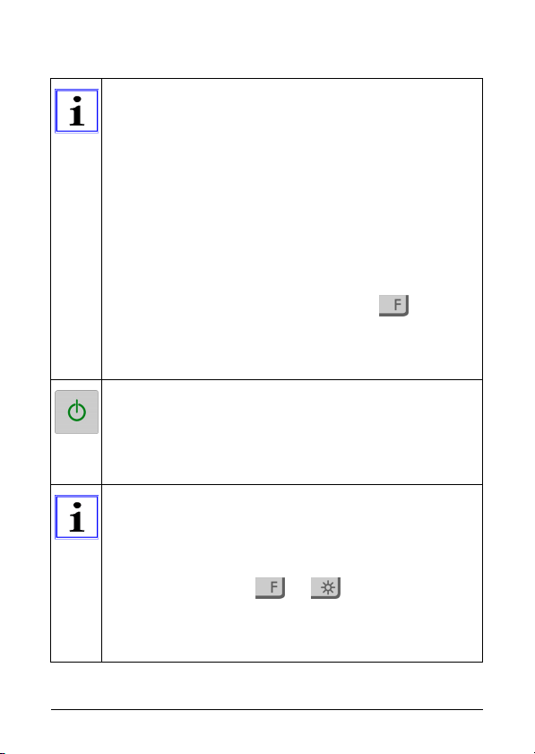
For activation of the unit press the on / off key. Subse-
quently - within approx. 2 seconds - press the relevant
key
The special commands are assigned grey symbols.
To activate a special command switch to the function
mode by shortly pressing function key , subse-
quently press the relevant command key. By pressing
the key combination once again you return to the main
functions.
Key for switching on / off and for activation of the setup
control.
After switching on, the instrument flashes with the last
set frequency. The current value will be saved
when switching off the instrument.
30 s after switching on the instrument, the display light
automatically dims for energy saving. It will take a quar-
ter of the settable operating time until the display switch-
es to the ‘standby’ - mode (display switch-off). The time
up to the complete automatic switch-off shall be selected
by using the function (see Mode 2). The
‘standby’ - mode is indicated by a red dot flashing at the
lower right corner as a “reminder”. Reactivate the display
by pressing any key (except for the on / off key).
Page 10 Operation manual HELIO-STROB micro2
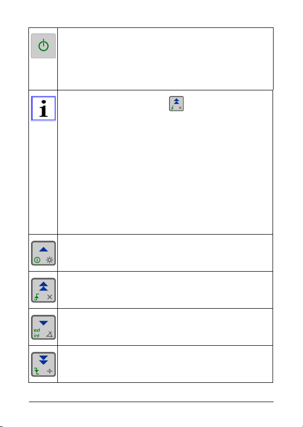
2. Main functions
Key for switching on / off and for activation of the setup
control.
Switch-on
Switch-off - 2 seconds after pressing or by double
clicking
Blue marked key areas e.g. stands for:
Changing the flash frequency
Reading back stored frequencies
Change the flash frequency in small steps
(+/- 1 – applied to the last indication position)
and large steps
(+/- 50 – applied to the penultimate indication position)
The absolute increment depends on the frequency
range. If the selected key is kept pressed over longer
time, the repeating function ‘repeat’ is activated.
Increase flash frequency by 1 x increment
Increase flash frequency by 50 x increments
Decrease flash frequency by 1 x increment
Decrease flash frequency by 50 x increment

Operation manual HELIO-STROB micro2 Page 11
Read back stored frequencies (max. 4) – by repeatedly
pressing this key – in the storage sequence
(see also frequency entry)
Display indication adjusts to selected flash frequency by
the decimal point. (number of decimal places)
3. Setup controls
Green symbols e.g. setup controls
For activation of the unit press the on / off key. Subse-
quently - within approx. 2 seconds - press the relevant
key (green symbol).
The unit will be switched off if no other button is pressed
after activation of the on / off key.
Frequency indication (Hz)
Indication [fps] – flashes
per second
Resolution:
max. 2 decimal points
(0.01 fps)
(red LED indication)
Frequency indication (fpm)
Indication [fpm] – flashes
per minute
Resolution:
max. 1 decimal place
(0.1 fpm)
(no red LED indication)
Page 12 Operation manual HELIO-STROB micro2
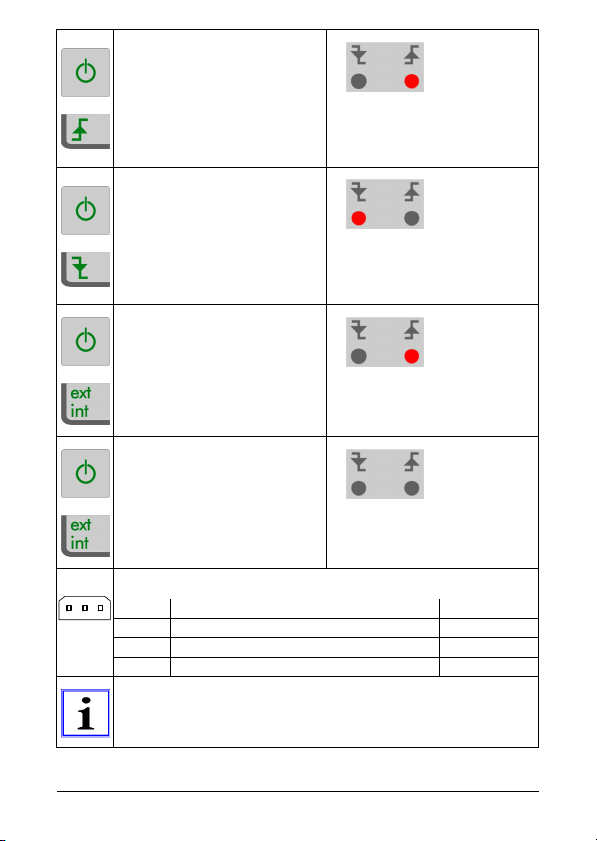
Direct flash triggering by
positive flank of the trigger
signal
(red LED indication)
Direct flash triggering by
negative flank of the trig-
ger signal
(red LED indication)
Switching to external trig-
gering (Standard mode:
Direct flash triggering by
positive flank of the trigger
signal)
(red LED indication)
Switching to internal trig-
gering: (triggering of the
flash impulse)
(no red LED indication)
Configuration of the trigger jack
Pin Function Colour
1 + 10 VDC max. 50 mA (Output) white
2 Trigger Input green
3 0 V (GND) brown
To facilitate the connection of external encoders to the
trigger jack, the delivery includes a ready-made cable.
123

Operation manual HELIO-STROB micro2 Page 13
To activate the “key lock” the unit must be switched
on. The “key lock” is activated by simultaneously press-
ing the on / off key and the SAFE button.
+
Key lock
Activate the same key se-
quence again to unlock
the keys and switch on.
The key lock prevents the unit from switching on acci-
dentally. By activation of the key lock the instrument set-
tings are saved and the HELIO-STROB micro2 is
switched off. The unit may be switched on again only if
you unlock the keys.
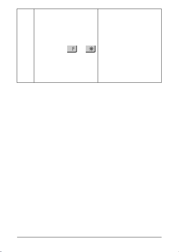
4. Special commands
Grey symbols e.g. Special commands
To activate the special commands, switch to the function
mode by shortly pressing function key , subsequent-
ly press the relevant command key.
Phase shifting*
Select between 0° and
360° by the up and down
keys (▲/▼).
Deactivate by repeating
the key combination
.
Store the selected value
by pressing the on / off key
in case of external trigger-
ing only.
red LED indication:
Function is activated
*see chapter
„Definition of terms“

Page 14 Operation manual HELIO-STROB micro2
Store frequencies
See also:
Read back stored
frequencies
Store frequently used
frequencies (max. 4).
Divide flash frequency
Activation, respectively
deactivation of an equally
increasing (2, 3, 4, 5...) di-
vision / multiplication of the
initial frequency.
Multiply flash frequen-
cies
red LED indication:
Function is activated
Attention:
To repeat division / multi-
plication activate re-
spectively without
pressing !!
The respective division or
multiplication factor is
shortly displayed.
Any switch between
and is possi-
ble, no intermediate
steps required. The ini-
tial value remains the
basic reference value.

Operation manual HELIO-STROB micro2 Page 15
The function to divide / multiply the flash frequency
serves the following applications:
to find the appropriate frequency by the integral multi-
plication / division of the initial frequency (*1)
to quickly reach the target frequency in case of signifi-
cant frequency changes or ranges.
(*1) Example:
Multiplication 11 – 22 - 33 – 44 – 55 - 66 [fps]...or
Division 300 – 150 – 100 – 75 – 60 [fpm]..or
With switch 300 – 150 – 100 150 – 300 [fpm]
Mode 1:
Flash duration
The selected flash duration
determines the sharpness
Selection of the flash dura-
tion in µs (1 µs – 100 µs)
alternatively:
in degrees (0.5° – 3,0°).
The alternatives are con-
secutively indicated within
a minimal value of 0.5°
and a maximal value of
100 µs.
Change duration by using
the up and down keys
(▲/▼).
Store by switching off and
on.
Page 16 Operation manual HELIO-STROB micro2
Mode 2:
Select the time up to the
complete switch-off of the
unit.
Repeated activation of key
combination
leads through Mode 1,
Mode 2 back to the fre-
quency indication.
Operating time up to the
complete automatic
switch-off in minutes -- --
(no limitation) up to max.
operating time of 30 min.
Change switch-off time by
using the up and down
keys (▲/▼).
Store by switching off and
on.
MAINTENANCE
1. Storage
If the HELIO-STROB micro2 is not used over more than four weeks,
the following measures should be taken:
Remove the battery from the instrument.
Protect the instrument from damage by properly storing it in a
dry room. Keep the instrument in the delivered hard shell in-
strument case.
When using other packing materials only anti-static materials
may be used. Statically charged packing materials may leed to
malfunctions of the instrument.
To avoid condensation see that the storage temperature is
kept. Storage temp.: -20° C ... +60° C (warming time constant
> 10 K/h).

Operation manual HELIO-STROB micro2 Page 17
2. Maintenance
According to the design, the HELIO-STROB micro2 is not suscepti-
ble to disturbance. However, the following should be basically ob-
served:
Do not throw the instrument and do not expose it to heavy
shocks.
Keep the instrument in the delivered hard shell instrument
case.
Clean the instrument by using only a soft, lightly-moist cloth.
Use only mild detergents.
3. Inspection / Calibration
As evidence of the high quality standards a PTB* traceable Calibra-
tion Certificate is available for the HELIO-STROB micro2. The re-
sults of inspections shall be documented in inspection sheets and
stored in a product database.
(*Physikalisch-Technische Bundesanstalt)
4. Dispatch / Transport
For the dispatch of the instruments we recommend to use the hard
shell instrument case that is included in the delivery. Before dis-
patching the instrument remove the batteries / accumulators from
the instrument. In case the instrument is dispatched without the
hard shell instrument case, only anti-static packing materials may
be used.
Page 18 Operation manual HELIO-STROB micro2
5. Repairs / Disposal
Instruments which are damaged or do not perform according to
their specifications shall not be used anymore. To provide for a safe
and functional instrument, only original spare parts shall be used for
repair.
Batteries shall be disposed of according to relevant le-
gal provisions. To dispose of the old instrument accord-
ing to legal rules and provisions, please send the HE-
LIO-STROB micro2 to the manufacturer.
If your instrument requires inspection / repair or disposal, please
send the unit DDU to:
ELMED Dr. Ing. Mense GmbH
Stroboskop-Service
Weilenburgstr. 39
D-42579 Heiligenhaus
Proper execution of maintenance and repair is guaran-
teed only by the manufacturer or by qualified and au-
thorised service centres.

Operation manual HELIO-STROB micro2 Page 19
Additional information
Definition of terms
Terms Explanation
LED Light emitting diode
Flash duration On-time of light emitting diodes
The setting in µs does not depend on the
frequency. The flash duration corresponds
to the time set. If set in degrees, the flash
duration depends on the frequency and
changes proportionally to the frequency.
The flash duration selected determines the
sharpness of the picture. The shorter the
flash duration, the sharper the contours of
the object under observation.
Triggering Trigger impulses for the flash sequence
(internal / external)
Rising flank Triggering occurs when trigger impulses
change from “0” to “1”
Falling flank Triggering occurs when trigger impulses
change from “1” to “0”
Flash frequency Number of light flashes per time unit
Display Indication for the display of pre-set values
RPM / fpm Number of revolutions per minute of the
object under observation
Hz / fps Repetition frequency per second of the
object under observation
Repeat – function Automatic function repetition of the key
being pressed longer
SAFE – Mode Instrument switch off and key lock activa-
tion
Phase shifting Random positioning of the object under
observation (0° – 360°)

Page 20 Operation manual HELIO-STROB micro2
Notes
______________________________________________________
______________________________________________________
______________________________________________________
______________________________________________________
______________________________________________________
______________________________________________________
______________________________________________________
______________________________________________________
______________________________________________________
______________________________________________________
______________________________________________________
______________________________________________________
______________________________________________________
______________________________________________________
______________________________________________________
______________________________________________________
______________________________________________________
______________________________________________________
______________________________________________________
This manual suits for next models
1
Table of contents
Other ELMED Test Equipment manuals


Popular Test Equipment manuals by other brands

Beha-Amprobe
Beha-Amprobe NCV-1000-EUR VOLTfix Series instruction manual

Tenma
Tenma 72-7910 manual

Bedfont
Bedfont GastroCH4ECK Gastrolyzer user manual

Ebyte
Ebyte E78-868TBL-02 user manual

Wolfgang Warmbier
Wolfgang Warmbier METRISO 3000 operating instructions

RHEINTACHO
RHEINTACHO RT STROBE qbLEDs quick start guide


