Wiltron 560-9 Series User manual

SERIES 560-9XXXX AND 5400-6XXXX SWR AUTOTESTERS
OPERATION AND MAINTENANCE MANUAL
1. INTRODUCTION
This manual provides product descriptions and
specifications for WILTRON Series 560-9XXXX and
5400-6XXXX SWR Autotesters (Figure 1). It also
includes Performance Verification procedures for
these components.
2. GENERAL DESCRIPTION
WILTRON SWR Autotesters are precision-balanced
Wheatstone bridges that contain an internal preci-
sion reference termination in one arm of the bridge.
Series 5400-6XXXX models have N or BNC type test
port connectors. Models 560-97XXX have N or
GPC-7 type test port connectors, and models
560-98XXX have WSMA or K type test port connec-
tors (see Table 1 on page 2).
These units are broadband microwave measurement
components that are used with the Model 562 Scalar
Network Analyzer and with Series 54XXX Scalar
Measurement Systems for making fixed-frequency
and swept-frequency return loss (SWR) measure-
ments. Return loss measurements are used over a
wide range of radio and microwave frequencies to
check the performance of systems, subsystems, and
microwave components such as amplifiers, direc-
tional couplers, attenuators, filters, splitters, and
terminations.
3. PERFORMANCE SPECIFICATIONS
Performance specifications for the SWR Autotesters
are listed in Table 1 (page 2).
4. EXPLANATION OF SWR
AUTOTESTER SPECIFICATIONS
Certain key specification terms are explained below.
a. Accuracy. This three-element term defines
the accuracy with which an SWR Autotester can
make a reflected signal measurement. The three
elements (0.01 ±0.06 ρ2) are described below.
1st Element: (0.01) is the directivity of the SWR
Autotester expressed as a reflection coefficient
(40 dB for this example, refer to Table 3 on
page 9).
2nd and 3rd Elements: ±0.06ρ2is the deprecia-
tion in accuracy due to test port mismatch (im-
pedance discontinuity). Element 2 (0.06) is the
inherent test port mismatch expressed as a re-
flection coefficient. The 3rd element, rho (ρ), is
the reflection coefficient of the device under test
(DUT). The entire expression describes the
measurement uncertainty caused by the re-
flected signal being re-reflected by the test port
mismatch.
b. Directivity. A figure of merit expressed in dB.
This figure represents the ratio of the power
levels as seen at the output port when (1) the
test port signal is fully reflected, and (2) the test
port is perfectly terminated.
c. Frequency Sensitivity. The maximum varia-
tion in output power/voltage that can be ex-
pected due to a change in frequency over the
specified range when the input power is held
constant
d. Output Time Constant. The amount of time
required for the selected output pulse to either
rise from the 10% to the 90% point or fall from
the 90% to the 10% point on the waveform.
490 JARVIS DRIVE ● MORGAN HILL, CA 95037-2809 P/N: 10100-00028
REVISION : B
PRINTED: NOVEMBER 1994
COPYRIGHT 1992 WILTRON CO.
Figure 1. Typical Series 560-9XXXX

Models Direc-
tivity
(dB) Accuracy➀➁ Freq
Sensi-
tivity
(dB)
Test Port
Conn. Physical
560-97XXXX Series SWR Autotesters, 10 MHz to 18GHz
➂
560- 0.01–8 GHz 8–18 GHz
-97A50 36 0.016 ±0.06ρ20.016 ±0.10ρ2±1.2 GPC–7
Dimension
s➄:
7.6 x 5.1 x 2.8 cm
(3 x 2 x 1 1⁄8in.)
Weight:
340 g (12 oz)
-97A50-1 40 0.010 ±0.06ρ20.010 ±0.10ρ2±1.2 GPC–7
-97N50 35 0.018 ±0.08ρ20.018 ±0.12ρ2±1.5 Type N (m)
-97N50-1 38 0.013 ±0.08ρ20.013 ±0.12ρ2±1.5 Type N (f)
-97NF50 35 0.018 ±0.08ρ20.018 ±0.12ρ2±1.5 Type N (f)
-97NF50-1 38 0.013 ±0.08ρ20.013 ±0.12ρ2±1.5 Type N (m)
560-98XXXX Series SWR Autotesters, 10 MHz to 40GHz
➃
560- 0.01–8 GHz 8–18 GHz 18–26.5 GHz 26.5–40 GHz
-98S50 37
36 0.018 ±0.10ρ20.018 ±0.10ρ2
0.025 ±0.13ρ2±2.0 WSMA (m)
Dimension
s➄:
1.9 x 3.8 x 2.9 cm
(3⁄4x 1-1⁄2x 1-1⁄8in.)
Weight:
198 g (7 oz)
-98S50-1 40
38 0.013 ±0.10ρ20.013 ±0.10ρ2
0.018 ±0.13ρ2±2.0 WSMA (m)
-98SF50 37
36 0.014 ±0.10ρ20.014 ±0.10ρ2
0.016 ±0.13ρ2±2.0 WSMA (f)
-98SF50-1 40
38 0.010 ±0.10ρ20.010 ±0.10ρ2
0.013 ±0.13ρ2±2.0 WSMA (f)
-98K50
-98KF50 35
32
30
0.018 ±0.15ρ20.018 ±0.15ρ2
0.026 ±0.15ρ2
0.032 ±0.18ρ2
±3.0 Type K (m)
Type K (f)
5400-6XXXX Series SWR Autotesters, 1 MHz to 3000 MHz
➂
5400- 1–1000 MHz 1000–2000 MHz 2000–3000 MHz
-6B75➅40 0.010 ±0.10ρ2BNC ➆
-6N50
-6NF50 40
40 0.010 ±0.05ρ2
0.010 ±0.05ρ20.010 ±0.05ρ2
0.010 ±0.05ρ2Type N (m)
Type N (f)
Dimensions
➄:
2.5 x 5.1 x 7.0 cm
(1 x 2 x 2-3⁄4in.)
Weight:
255 g (9 oz)
-6N75➅
-6NF75➅40
40 0.010 ±0.05ρ2
0.010 ±0.05ρ20.010 ±0.05ρ2
0.010 ±0.05ρ20.010 ±0.08ρ2
0.010 ±0.08ρ2Type N (m)
Type N (f)
All Models:
Input Port Impedance: 50Ω
Insertion Loss (from input to test port): 6.5 dB nominal
Detector Output Polarity: Negative
Output Time Constant: 2 µs
Maximum Power Input: 0.5 watts (+27 dBm)
Cable Length:
122 cm (4 ft.)
➀Where ρis the reflection coefficient being measured. Accuracy includes the effects of test port reflections and directivity.
➁See paragraph 4 for explanation of accuracy and other terms.
➂Input Connector: Type N Female
➃Input Connector: Ruggedized Type K Female
➄Plus connectors and cable
➅Impedance 75Ω
Table 1. SWR Autotester Performance Specifications
2SWR OMM

5. PRECAUTIONS FOR USE OF SWR
AUTOTESTERS
WILTRON SWR Autotesters are high-quality, preci-
sion laboratory instruments and should receive the
same care and respect afforded such instruments.
Follow the precautions listed below when handling
or connecting these devices. Complying with these
precautions will guarantee longer component life
and less equipment downtime due to connector or
device failure. Also, such compliance will ensure that
SWR Autotester failures are not due to misuse or
abuse—two failure modes not covered under the
WILTRON warranty.
a. Beware of destructive Pin Depth of Mating
Connectors. Based on RF components re-
turned for repair, destructive pin depth of mat-
ing connectors is the major cause of failure in the
field. When an RF component connector is mated
with a connector having a destructive pin depth,
damage will usually occur to the RF component
connector. A destructive pin depth is one that is
too long in respect to the reference plane of the
connector (Figure 2).
The center pin of a precision RF component con-
nector has a precision tolerance measured in
mils (1/1000 inch). The mating connectors of
various RF components may not be precision
types. Consequently, the center pins of these de-
vices may not have the proper depth. The pin
depth of DUT connectors should be measured to
assure compatibility before attempting to mate
them with SWR Autotester connectors. A
WILTRON Pin Depth Gauge (Figure 3), or
equivalent, can be used for this purpose.
If the measured connector is out of tolerance in
the “+” region, the center pin is too long (see
Table 2). Mating under this condition will
probably damage the precision RF component
connector. If the test device connector measures
out of tolerance in the “–” region, the center pin
is too short. This will not cause damage, but it
will result in a poor connection and a consequent
degradation in performance.
REFERENCE
PLANE
MALE
PIN
DEPTH
(INCHES)
REFERENCE
PLANE
FEMALE
PIN
DEPTH
(INCHES)
Figure 2. N Connector Pin Depth Definition
0
1
2
3
45
1
2
3
4
211
2
Figure 3. Pin Depth Gauge
Test Port
Connector
Type
WILTRON
Gauging
Set Model
Pin Depth
(Mils)
Pin Depth
Gauge
Reading
N-Male
01-163
207 –0.000
+0.003* 207 +0.000
–0.003*
N-Female 207 +0.000
–0.003* Same as
Pin Depth
GPC-7 01-161 +0.000
–0.003 Same as
Pin Depth
WSMA-
Male 01-162
–0.0025
–0.0035 Same as
Pin Depth
WSMA-
Female –0.003
–0.007
K-Male,
K-Female 01-162 +0.000
–0.005 Same as
Pin Depth
∗0.005 for 5400-6XXXX Series SWR Autotesters
Table 2. Allowable Mating Connector Pin Depth
SWR OMM 3

b. Avoid Over Torquing Connectors. Over tor-
quing connectors is destructive; it may damage
the connector center pin. Finger-tight is usually
sufficient for Type N connectors. Always use a
connector torque wrench (8 inch-pounds) when
tightening GPC-7, WSMA, or K type connectors.
Never use pliers to tighten connectors.
c. Avoid Mechanical Shock. SWR Autotesters
are designed to withstand years of normal bench
handling. However, do not drop or otherwise
treat them roughly. Mechanical shock will sig-
nificantly reduce their service life.
d. Avoid Applying Excessive Power. Series
560-9XXXX and Series 5400-6XXXX SWR
Autotesters are rated at +27 dBm (0.5W) maxi-
mum input power. Exceeding this input power
level, even for short durations, can permanently
damage their internal components.
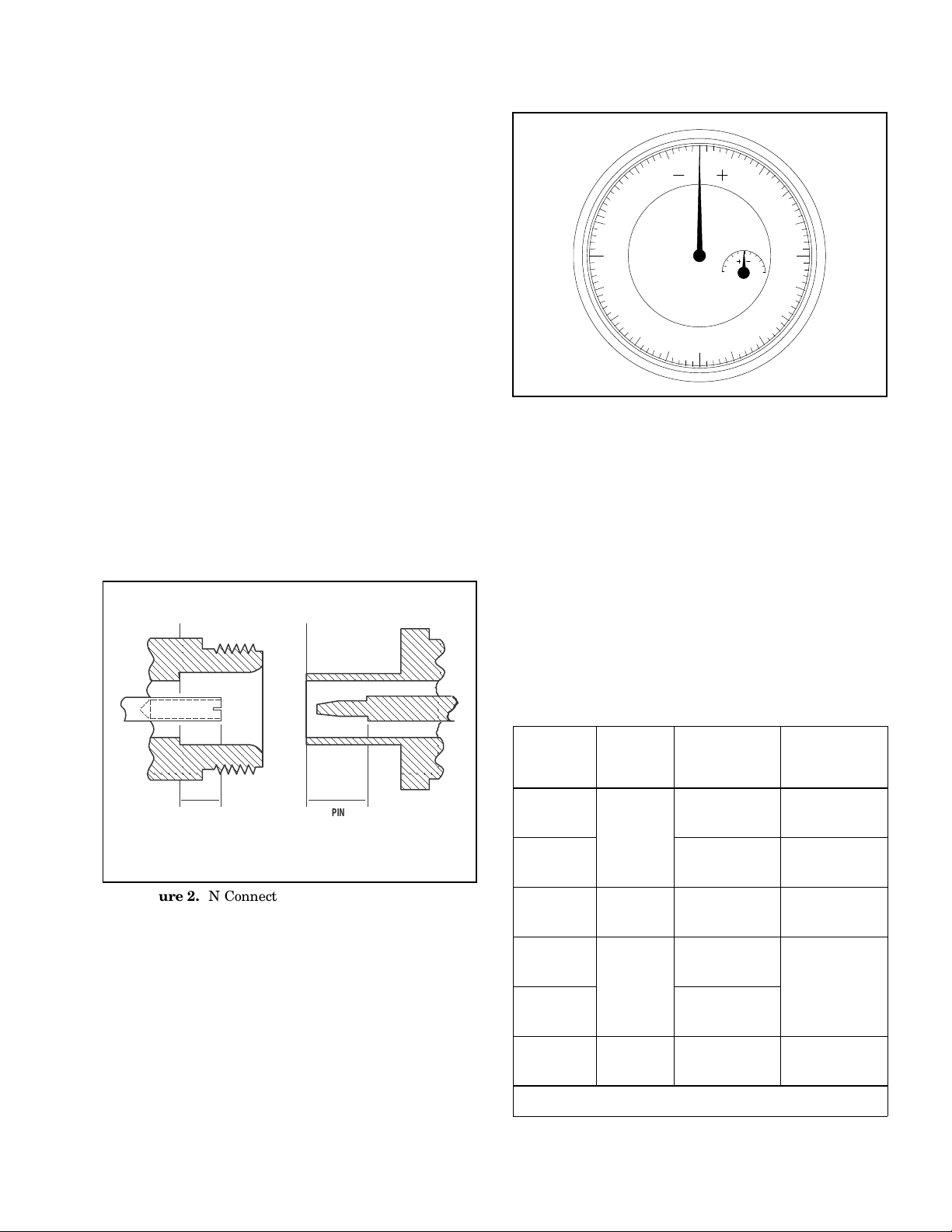
e. Do Not Disturb Teflon Tuning Washers On
Connector Center Pins. The center conduc-
tor of many RF component connectors contains
a small teflon tuning washer that is located near
the point of mating (Figure 4). This washer com-
pensates for minor impedance discontinuities at
the interface. Do not disturb this washer. The
location of this washer is critical to the perform-
ance of the RF component.
f. Compensation Washers (WSMA Connec-
tors). WSMA connectors are optimized for con-
nection to standard SMA connectors. Whenever
two WSMA connectors are mated, a metallic
compensation washer should be inserted
between the two connectors at the point of mat-
ing (to provide electrical compensation for this
connector combination). The only exceptions are
the WSMA Open/Short and the RF Output con-
nectors of the 54XXX and other WILTRON RF
signal sources. A vial containing five of these
washers (P/N ND38252) is packaged with each
Series 19SX50 Air Line. Figure 10, beginning on
page 11, describes the procedure for installing
these washers.
g. Keep Connectors Clean. The precise geom-
etry that makes possible the RF component’s
high performance can be easily disturbed by dirt
and other contamination adhering to connector
interfaces. When not in use, keep the connectors
covered. Refer to paragraph 7 for cleaning in-
structions.
6. PERFORMANCE VERIFICATION
Performance verification consists of measuring the
directivity of the SWR Autotester and measuring
connector pin depth.
6.1. Pin Depth Measurement
Gauging sets for measuring the pin depth of the test
port connectors of SWR Autotesters and other preci-
sion RF components are available from WILTRON.
Table 2 lists the appropriate gauging set for each
connector type used on Series 560 and 5400 SWR
Autotesters. Refer to the instructions for gauging
connectors that are provided with each gauging set.
Refer also to the pin-depth specifications in Table 2
for each connector type.
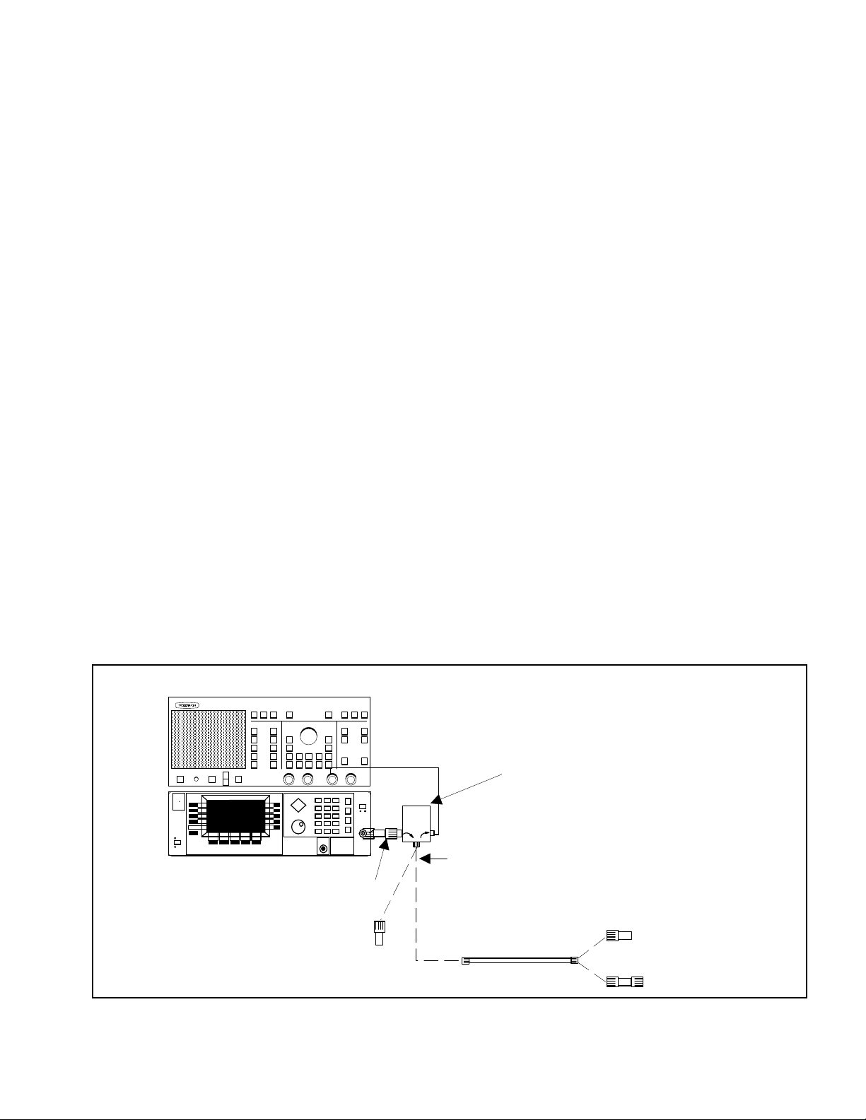
6.2. Directivity Measurements
Directivity measurements are frequency limited. For
frequencies above 2 GHz, a magnified reflection tech-
nique (air line) measurement is used. Below 2 GHz,
where an air line is not effective, an error averaging
measurement method is used.
Table 3 (page 6) lists recommended test equipment
for performing these measurements. Measurement
procedures are given below.
Measuring the directivity of Series 560-9XXXX SWR
Autotesters above 2 GHz requires the use of a Series
18XX540 or 19XX50 Air Line that matches the test
port connector of the SWR Autotester being tested
(see Table 3). If a series 19SX50 air line is used
(WSMA connectors), compensation washers are re-
TEFLON WASHER
NOTE
The teflon washer is shown on a GPC-7
connector. A similar washer may be installed
on any WILTRON precision connector.
Figure 4. Tuning Washer on GPC-7 Connector
4SWR OMM

quired; refer to paragraph 5f. Figure 10 (page 11)
describes the procedure for installing these washers.
The directivity measurement procedures described
in the following paragraphs use a Model 562 Scalar
Network Analyzer (SNA) in conjunction with an ap-
propriate 68XXXA/B Synthesizer. The setup for this
equipment configuration is described below in para-
graph a. These procedures can also be performed
using an appropriate model 54XXX Scalar Measure-
ment System (SMS); the setup for this configuration
is described in paragraph b. The actual measure-
ment procedures are described in paragraph c(>2
GHz) and paragraph d(<2 GHz).
a. Equipment Setup — Using 562 SNA
1. Connect test setup as shown in Figure 5.
2. Press the LINE key on the 68XXXA/B signal
source to OPERATE.
3. Press the POWER key on the 562 network
analyzer to ON.
4. Press the SYSTEM key on the signal source,
then select the Reset key, from the displayed
menu.
5. Set the signal source for frequency range of
the SWR Autotester under test and for maxi-
mum possible power, as described below.
(a) Press CW/SWEEP SELECT key.
(b) Select the Analog softkey from the dis-
played menu.
(c) Select the Edit F1 softkey from the dis-
played menu.
(d) Using the Cursor Control Key or Rotary
Data Knob, edit the F1 parameter to
equal the low-end frequency of the SWR
Autotester under test.
(e) Select the Edit F2 softkey and repeat
step (d) for the high-end frequency.
(f) Select the Edit L1 softkey and repeat
step (d) for the source’s maximum power
level.
6. Press SYSTEM FUNCTION MENU key on the
network analyzer.
7. Using MENU up-down keys, highlight RESET,
then press SELECT key.
8. Press GRATICULE ON/OFF key to ON.
9. Proceed to paragraph c.
b. Equipment Setup — Using 54XXX SMS
1. Connect test setup as shown in Figure 6.
2. Press the POWER key on the 54XXX to ON.
3. Press SYSTEM MENU key .
4. Using MENU up-down keys: Highlight
RESET,then press the SELECT key.
AIR LINE
OPEN/SHORT
34-SERIES
ADAPTER
562 SCALAR NETWORK ANALYZER
20 dB OFFSET
CONNECT DASHED LINE CONNECTIONS
WHEN DIRECTED BY PROCEDURE
SWR AUTOTESTER UNDER TEST
REFERENCE TERMINATION
(<2 GHz MEASUREMENTS)
A
68XXXA/B SYNTHESIZER
Figure 5. Test Equipment Setup for Directivity Measurement Using 562 Scalar Network Analyzer
SWR OMM 5

5. Press the FREQUENCY key and set the
START frequency to the low-end frequency of
the SWR Autotester.
6. Set the STOP frequency to the high-end fre-
quency of the SWR Autotester.
CONNECT DASHED LINE CONNECTIONS
WHEN DIRECTED BY PROCEDURE
AIR LINE
OPEN/SHORT
34-SERIES
ADAPTER
20 dB OFFSET
SWR AUTOTESTER UNDER TEST
REFERENCE TERMINATION
(<2 GHz MEASUREMENTS)
54XXX SCALAR MEASUREMENT SYSTEM
A
Figure 6. Test Equipment Setup for Directivity Measurement Using 54XXX Scalar Measurement System
Instrument Required Characteristics Recommended Model
and Manufacturer
Scalar Network Analyzer System*
Includes:
Scalar Network Analyzer
Vertical Sensitivity: 0.5 dB/Div.
Variable Offset Control
Sweep Generator
or
Synthesizer
Leveled Output: ±1.0 dB
Frequency Range: 2 – 18 GHz
WILTRON 562 SNA and
WILTRON Series 68XXXA/B
Synthesizer
or
WILTRON 54XXX Scalar
Measurement System
Air Line GPC-7 Connector (SWR: 1.003
Type N/NF Connector (SWR: 1.006)
WSMA Connector (SWR: 1.006)
K Connector (SWR: 1.020)
WILTRON 18A50
WILTRON 19NX50 Series
WILTRON 19SX50 Series
WILTRON 19KX50 Series
Termination 20 dB Offset WILTRON 29 Series
Precision Termination
50
±
0.5 Ohms
GPC-7 Test Port Connector
Type N Test Port Connector
WSMA Female Test Port Connector
WSMA Male Test Port Connector
75
±
0.5 Ohms
Type N Male Test Port Connector
Type N Female Test Port Connector
BNC Test Port Connector
WILTRON:
28A50-1
26N50
28S50
28SF50
WILTRON:
26N75
26NF75
26B75
Table 3. Recommended Test Equipment
6SWR OMM

c. Directivity Measurement — 2 GHz and
above
1. On the network analyzer, Press CHANNEL 2
key to OFF.
2. Press CHANNEL 1 MENU key.
3. Using the MENU up-down keys: Highlight
RETURN LOSS, then press SELECT key.
4. Press the CALIBRATION key.
5. Using the MENU up-down keys: Highlight
START CAL, then press the SELECT key.
6. Connect SWR Autotester to INPUT A, if you
have not done so yet.
7. Connect the beadless end of the air line to the
SWR Autotester test port. Pay careful atten-
tion to making a good connection. Refer to
Figure 7, which shows examples of good and
bad connections. If you are using 19SX50 se-
ries air lines (WSMA connectors), use a com-
pensation washer as shown in Figure 10 (page
11).
8. Connect OPEN to air line and press SELECT
key.
9. Connect SHORT to air line and press SELECT
key.
10. Connect 20 dB Offset Termination to air line
and press SELECT key.
11. Press CHANNEL 1 MENU key.
12. Using the MENU up-down keys: Highlight
REF LINE and press SELECT key. Then
highlight ON and again press SELECT key.
13. Using DATAENTRY knob, set reference line to
forth graticule line from top (Figure 8).
Figure 7. Examples of Good and Bad Air Line Connections.
BAD GOOD
REFERENCE LINE POSITION
Figure 8. Reference Line Position
SWR OMM 7

14. Press CHANNEL 1 AUTOSCALE key.
15. Press CHANNEL 1 OFFSET/RESOLUTION
key.
16. Using MENU up-down keys: Highlight
OFFSET dB, then press SELECT key.
17. Using the DATA ENTRY/CURSOR knob, align
the Channel 1 signal with the reference line
(Figure 9).
NOTE
The OFFSET value displayed at the
top of the display should be the ap-
proximately value of the Offset
Termination used.
18. Observe the displayed ripple pattern: Select
the ripple with the greatest amplitude and
use the DATA ENTRY/CURSOR knob to repo-
sition the waveform so that the average point
of the selected ripple is on the reference line.
Read the OFFSET value from the top of the
display.
NOTE
The average point is approximately
halfway between the peak and
trough values for ripples 3 dB or
less. For ripples greater than 3 dB,
refer to Table 4.
19. Measure the peak-to-peak value of the se-
lected ripple.
20. In the “REF ±X, Peak to Peak Ripple, dB”
column of Table 4, find the value nearest to
the peak-to-peak signal value measured in
step 19.
21. Read the coordinate value from the “X dB
Below Reference” column of the table.
22. Add the “X dB Below Reference” value from
step 21 to the value read in step 18. The sum
is the worst-case directivity of the SWR Auto-
tester. It should equal or exceed the specifica-
tion for the SWR Autotester in Table 1.
d. Directivity Measurements Below 2 GHz.
1. If using 562 SNA as measurement system,
perform setup procedure in subparagraph a.
Or, if using 54XXX SMS, perform setup proce-
dure in subparagraph b.
2. Perform steps 1 thru 5 of subparagraph c.
3. Connect termination to test port of SWR
Autotester being measured*.
4. Press CHANNEL 1 MENU key.
5. Using MENU up-down keys: Highlight REF
LINE, then press SELECT key.
6. Using DATAENTRY knob, set reference line to
midscale.
7. Press CHANNEL 1 OFFSET/RESOLUTION
key.
8. Using MENU up-down keys: Highlight OFF-
SET dB,then press SELECT key.
9. Using DATA ENTRY knob, set OFFSET dB for
the directivity value of the SWR Autotester
being measured (refer to Table 1).
10. Using MENU up-down keys: Highlight RES-
OLUTION dB/DIV,then press SELECT key.
11. Using DATA ENTRY knob, set RESOLUTION
dB/DIV for a convenient value.
12. Observe the display. If the measured directiv-
ity signal is below the reference line at all
frequencies, then the directivity is within the
specified value.
∗The return loss of the termination used for this test must be
higher than the directivity of the SWR Autotester being meas-
ured. The WILTRON terminations recommended in Table 3
meet this requirement.
REFERENCE LINE
Figure 9. Signal Aligned With the Reference Line
8SWR OMM

7. MAINTENANCE
WILTRON recommends that no maintenance other
than cleaning be attempted by the customer. The
SWR Autotester should be returned to WILTRON for
repair and/or service when needed.
To clean the connector interfaces, use a clean cotton
swab that has been dampened with denatured
alcohol. Proper techniques for cleaning male and
female GPC type connectors are as follows.
•Always use denatured alcohol as cleaning
solvent. Never use industrial solvent or water,
as damage to the connectors may result.
•Do not use excessive amount of alcohol as pro-
longed drying of the connector may be required
as a result.
•Never put lateral pressure on the center pin of
the connector.
•If installed, do not disturb the teflon washer on
the center conductor pin (refer to para-
graph 5e).
•Verify that no cotton or other foreign material
remains in the connector after cleaning it.
•If available, use compressed air to remove for-
eign particles and to dry the connector.
•After cleaning, verify that the center pin has
not been bent or damaged.
CAUTION
Excessive pressure when cleaning can
damage the center pin of the connector.
Ensure that the cotton swab is small
enough to fit into the connector without
applying pressure on the center conduc-
tor. When cleaning, limit the pressure so
as to lightly contact the connector. To ob-
tain cotton swabs that smaller than the
standard type available in most retail out-
lets, try contacting a medical-labratory-
type supply center.
SWR OMM 9

Relative to Unity Reference
SWR Reflection
Coefficient
Return
Loss
(dB)
X
dB Below
Reference
REF + X
dB REF – X
dB
REF ±X
Peak to Peak
Ripple dB
17.3910
8.7242
5.8480
4.4194
3.5698
0.8913
0.7943
0.7079
0.6310
0.5623
1
2
3
4
5
1
2
3
4
5
5.5350
5.0780
4.6495
4.2489
3.8755
–19.2715
–13.7365
–10.6907
–8.6585
–7.1773
24.8065
18.8145
15.3402
12.9073
11.0528
3.0095
2.6146
2.3229
2.0999
1.9250
0.5012
0.4467
0.3981
0.3548
0.3162
6
7
8
9
10
6
7
8
9
10
3.5287
3.2075
2.9108
2.6376
2.3866
–6.0412
–5.1405
–4.4096
–3.8063
–3.3018
9.5699
8.3480
7.3204
6.4439
5.6884
1.7849
1.6709
1.5769
1.4985
1.4326
0.2818
0.2512
0.2239
0.1995
0.1778
11
12
13
14
15
11
12
13
14
15
2.1567
1.9465
1.7547
1.5802
1.4216
–2.8756
–2.5126
–2.2013
–1.9331
–1.7007
5.0322
4.4590
3.9561
3.5133
3.1224
1.3767
1.3290
1.2880
1.2528
1.2222
0.1585
0.1413
0.1259
0.1122
0.1000
16
17
18
19
20
16
17
18
19
20
1.2778
1.1476
1.0299
0.9237
0.8279
–1.4988
–1.3227
–1.1687
–1.0337
–0.9151
2.7766
2.4703
2.1986
1.9574
1.7430
1.1957
1.1726
1.1524
1.1347
1.1192
0.0891
0.0794
0.0708
0.0631
0.0562
21
22
23
24
25
21
22
23
24
25
0.7416
0.6639
0.5941
0.5314
0.4752
–0.8108
–0.7189
–0.6378
–0.5661
–0.5027
1.5524
1.3828
1.2319
1.0975
0.9779
1.1055
1.0935
1.0829
1.0736
1.0653
0.0501
0.0447
0.0398
0.0355
0.0316
26
27
28
29
30
26
27
28
29
30
0.4248
0.3796
0.3391
0.3028
0.2704
–0.4466
–0.3969
–0.3529
–0.3138
–0.2791
0.8714
0.7765
0.6919
0.6166
0.5495
1.0580
1.0515
1.0458
1.0407
1.0362
0.0282
0.0251
0.0224
0.0200
0.0178
31
32
33
34
35
31
32
33
34
35
0.2414
0.2155
0.1923
0.1716
0.1531
–0.2483
–0.2210
–0.1967
–0.1751
–0.1558
0.4897
0.4365
0.3890
0.3467
0.3090
1.0322
1.0287
1.0255
1.0227
1.0202
0.0158
0.0141
0.0126
0.0112
0.0100
36
37
38
39
40
36
37
38
39
40
0.1366
0.1218
0.1087
0.0969
0.0864
–0.1388
–0.1236
–0.1100
–0.0980
–0.0873
0.2753
0.2454
0.2187
0.1949
0.1737
1.0180
1.0160
1.0143
1.0127
1.0113
0.0089
0.0079
0.0071
0.0063
0.0056
41
42
43
44
45
41
42
43
44
45
0.0771
0.0687
0.0613
0.0546
0.0487
–0.0778
–0.0693
–0.0617
–0.0550
–0.0490
0.1548
0.1380
0.1230
0.1096
0.0977
1.0101
1.0090
1.0080
1.0071
1.0063
0.0050
0.0045
0.0040
0.0035
0.0032
46
47
48
49
50
46
47
48
49
50
0.0434
0.0387
0.0345
0.0308
0.0274
–0.0436
–0.0389
–0.0346
–0.0309
–0.0275
0.0871
0.0776
0.0692
0.0616
0.0549
1.0057
1.0050
1.0045
1.0040
1.0036
0.0028
0.0025
0.0022
0.0020
0.0018
51
52
53
54
55
51
52
53
54
55
0.0244
0.0218
0.0194
0.0173
0.0154
–0.0245
–0.0218
–0.0195
–0.0173
–0.0155
0.0490
0.0436
0.0389
0.0347
0.0309
1.0032
1.0028
1.0025
1.0022
1.0020
0.0016
0.0014
0.0013
0.0011
0.0010
56
57
58
59
60
56
57
58
59
60
0.0138
0.0123
0.0109
0.0097
0.0087
–0.0138
–0.0123
–0.0109
–0.0098
–0.0087
0.0275
0.0245
0.0219
0.0195
0.0174
Table 4. Microwave Measurement
Conversion tables for Return Loss, Reflection Coefficient, and SWR with tabular values for interaction of
a small phasor X with a large phasor (unity reference) expressed in dB related to reference.
PHASOR
INTERACTION
X
(1 + X)
(REF)
(1 - X)
TERM002.DRW
10 SWR OMM

Step1. Separate a single WSMA connector
compensation washer and trim
away the interconnecting tabs.
Step 2. Connect the 560-98SF50 SWR
Autotester input port to the signal
source RF output port, and loosely
tighten connector. Orient the
WSMA female connector (test port)
up.
Step 3. Insert the compensation washer
into the opening of the WSMA fe-
male connector, as shown.
Step 4. Connect beaded end of the air line
per application. Tilt the air line hori-
zontally. At the unbeaded end, cen-
ter the inner conductor with the cen-
ter of the connector opening.
Figure 1. Installing Compensation Washers on WSMA Connectors (1 of 2)
SWR OMM 11

Step 5. Loosen the SWR Autotester input
port connector and rotate unit hori-
zontally, as shown at the right.
Align the unbeaded end of Air Line
with test port connector and care-
fully mate connectors. Tighten all
connectors carefully.
NOTE
For a 560-98S50 SWR Autotester (male WSMA
test port) in combination with a 19SF50 Air
Line, insert the compensation washer into the
female WSMA connector of the air line (beaded
end).
Figure 10. Installing Compensation Washers on WSMA Connectors (2 of 2)
12 SWR OMM

WARRANTY
The WILTRON product(s) listed on the title page is (are) warranted against defects in
materials and workmanship for one year from the date of shipment.
WILTRON’s obligation covers repairing or replacing products which prove to be defective
during the warranty period. Buyers shall prepay transportation charges for equipment
returned to WILTRON for warranty repairs. Obligation is limited to the original pur-
chaser. WILTRON is not liable for consequential damages.
LIMITATION OF WARRANTY
The foregoing warranty does not apply to WILTRON connectors that have failed due to
normal wear. Also, the warranty does not apply to defects resulting from improper or
inadequate maintenance by the Buyer, unauthorized modification or misuse, or operation
outside of the environmental specifications of the product. No other warranty is expressed
or implied, and the remedies provided herein are the Buyer’s sole and exclusive remedies.
TRADEMARK ACKNOWLEDGEMENTS
V Connector and K Connector are registered trademarks of WILTRON Company.
NOTICE
WILTRON Company has prepared this manual for use by WILTRON Company personnel
and customers as a guide for the proper installation, operation and maintenance of
WILTRON Company equipment and computer programs. The drawings, specifications,
and information contained herein are the property of WILTRON Company, and any
unauthorized use or disclosure of these drawings, specifications, and information is
prohibited; they shall not be reproduced, copied, or used in whole or in part as the basis
for manufacture or sale of the equipment or software programs without the prior written
consent of WILTRON Company.
SWR OMM 15
This manual suits for next models
20
Table of contents
Other Wiltron Test Equipment manuals