e-mail:
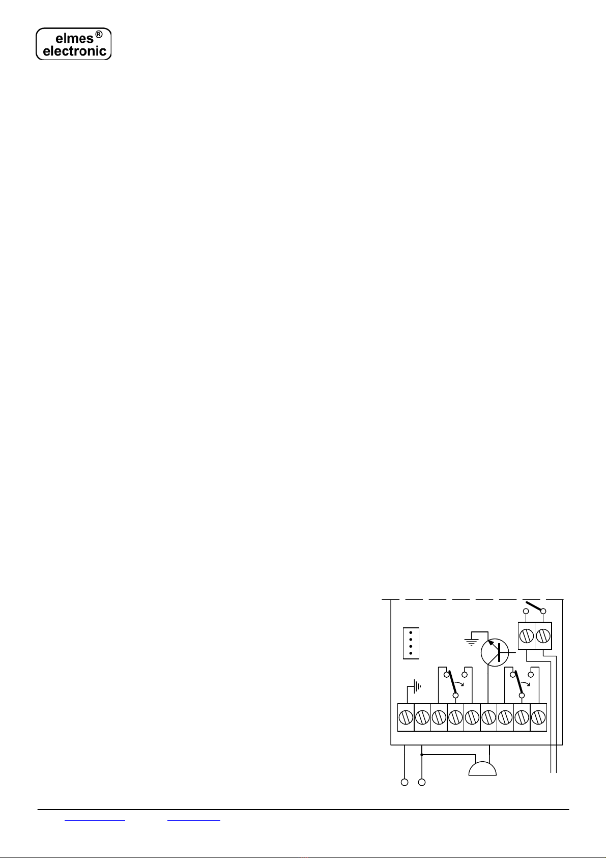
[email protected] internet: www.elmes.pl Elmes Elektronik 06.2006. All rights reserved. +NC1 NO1 NC2 NO2S
_
12 - 24 V
buzzer
+
_
tamper
odbiornik / receiver
TX
1
ACCESS CONTROL RECEIVER WITH TWO RELAY OUTPUTS AND LED DISPLAY
Model RD448 for up to 448 key-fob transmitter users and event memory log.
Model RD1000 for up to 1000 key-fob transmitter users.
This receiver is designed to use in remote control and access control systems with large number of key-fob transmitter users and required high
level of access control verification security. To achieve intended functional performance the receiver includes the following features & func-
tions:
- 448 key-fob transmitter user memory (model RD1-448) or 1000 key-fob transmitter users memory (model RD1-1000),
- possibility of deleting a single key-fob user without need to clear entire user memory,
- high security KEELOQ®dynamic code hopping key-fob user identification system,
- three digit bright LED display for user number display, easy programming, user learning and deleting,
- very sensitive radio superhet receiver allowing better data signal selectivity and better operating range,
- non-volatile memory log of last 6144 events (model RD1-448 only) including date, user number and key-fob button,
- TAMPER switch for receiver’s case opening detection,
- wide range of power supply voltages: 10…35VDC or 24VAC.
Operation.
The use of a key-fob transmitter earlier learned to the receiver’s memory sets on its one of two relay outputs for:
-certain user programmed period of time (pulse – mono stable operation), or
-until a next use of key-fob transmitter is made ( on/off - bistable operation).
The digital LED display will indicate number of used key-fob transmitter while receiver’s power on LED will change color (only if output one is
set to on). Two pulses signal on relay set on and one pulse signal on relay set off would be generated at the receiver’s signal output S. Also, the
event will be memorized in non-volatile event memory log for future reference.
Event memory log.
The receiver is capable of memorizing last 6144 events. Every time a valid command from key-fob transmitter is received, it’s user number
(0…447) is registered in the memory log along with information on used transmitter’s button (0..1) and current time. The content of the re-
ceiver’s event memory log may be read/printed out for reference or verification with the help of external personal computer (PC). Connection of
the receiver and the PC is made through a voltage conversion cable RS232(+12/-12V)<->TTL (0/5V) connected to the PC’s RS232 serial bus.
Schematic diagram of the cable is shown further on in the manual and the cable may be ordered from receiver seller. Dedicated software in
English “RD reader” supporting data log reading may be downloaded free from manufacture’s web site www.elmes.pl. The software allows
reading out and saving of event chronological data log to PC in form of Microsoft Access®(*.mdb) data base file. Advanced editing and report
listing of the *.mdb data file content may be done using Microsoft Access®, Lotus Approach®or Open Office®commercial software.
RD receiver users are advised to read out the event memory data log the more frequently the higher the number of key-fob transmitters in the
receiver’s memory. In a sample system with 448 key-fobs and their estimated double use daily, receiver’s event log will overflow after approxi-
mately 6 days. New event data is overwritten on existing data log in the memory.
Internal clock-timer.
Though the RD receiver’s memory is non-volatile type protecting data content in case of power cut off failure, the internal clock timing device is
not protected and will stop on power off. Registered event data after power supply is restored will therefore have incorrect timing, proportionally
to the power cut off timing. In order to maintain correct event timing, a battery backup power supply of the receiver must be used.
The RD1000 model. In this version, entire RD memory is allocated to extended 1000 user key-fob memory thus will not register any events.
Access Control.
As mentioned earlier, the event memory log may be read out with special PC software support for external back up, listing and edition. Addi-
tionally, thanks to the microprocessor special operating mode obtained by shorting its 5th and 6th pins, the RD receiver may be used to form a
unique access control and user rejection system. In that case, key-fob transmitter number of every received command is made available at TX
series output (*). If then, within 100ms time duration, a logical 0 is not forced to series RX connector, the receiver’s relay output will remain off.
This feature simplifies designing an access control system in witch one or more key-fob users may be temporarily or permanently restricted from
entering secured premises. Important! In this operating mode, the content of event memory log can not be downloaded to PC.
(*) In ASCII format as: “NNN-P” followed by CR and LF commands, where NNN stands for key-fob number and P (0 or 1) for button used.
Description of jumpers.
JP1 closed will result in key-fob number display for only 5 seconds. Opened will dis-
play last key-fob number until next key-fob is used.
JP2 closed will result that only one output channel is active and responds to any user
selected key-fob transmitter button. Opened, both output channels are active and
respond to respective two buttons of used key-fob, e.g. buttons 1 & 2 or 3 & 4 of
Elmes CH4H transmitter.
Installation.
RD receiver operates indoor at ambient temperature range from 0 to +40°C. Installation
place should be dry and far from any electromagnetic power lines, radio transmitters,
metal screening and other devices that may cause interference and reduce operation
range. External antenna should be used via coaxial cable connected to receiver’s ANT
terminals if the receiver is to be installed inside any metal screened housing. Practical
tests should be taken prior to firm installation to determine exact operation range. Stan-
dard wire antenna should be let loose downwards and not fixed or glued to ground.
Receiver’s installation is shown on schematic diagram. The second channel relay outputs
(NC2 and NO2) are not operational with jumper JP2 closed. Integral switching power
supply of the receiver allows connection of wide range of external voltages ranging from
10…35VDC to 24VAC. Important! External buzzer can be connected to the DC volt-
age powered RD receiver only (see schematic diagram).


