TWENTY OUTPUT CHANNELS HOPPING CODE RECEIVER CH20H (EN)
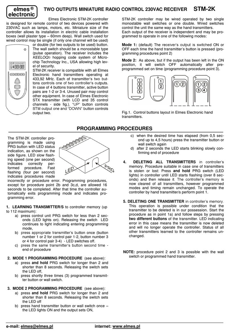
This microprocessor controlled 20 output channels radio receiver is designed to operate with large number of hopping code transmitters in wireless alarms and access
control systems. It features KEELOQ® code hopping transmitter verification system allowing highest level of security. The receiver provides 20 galvanic separated
NC/NO relay outputs, each with front panel LED indication. Other features include transmitter’s low battery warning indication and, in operation with selected
transmitters, radio communication failure and transmitter’s case opening sabotage protection signaling. The CH20H receiver operates with all Elmes Electronic made
434MHz band transmitters.
Each receiver channel may have pre-programmed any number of Elmes transmitters with total number operating with one CH20H receiver not exceeding 60. Next
transmitter learned will delete the first in receiver’s memory. Multi channel hand transmitters and RP501 transmitter learned to the receiver always control consecutive
adjacent channels. Wireless detectors PTX50, GBX1 and CTX4H operate in two output channels of the receiver: motion alarm detection signaled in any channel 1...20
while sabotage alarm (TAMPER) signaled in channel 20 assigned automatically. Typical application fields of CH20H receiver include:
- interfacing to any wired control panel Elmes made wireless detector transmitters such as CTX, GBX, PTX and RP501 as well as key-fob transmitters (e.g.
UMB100H) for system remote arming and disarming.
- designing an alert call-in system or wireless panic button –where personnel equipped with hand transmitters (e.g. AN200H or UMB100H) can actuate a call-in
request or actuate panic alarm calling for help.
Receiver’s outputs operation modes.
Actuating transmitter programmed to the receiver results in setting its channel relay output ON and illuminating channel’s LED indicator. Output relays’ SET ON
timing depends on one of three operation modes described below, individually programmed to each output channel of the receiver.
1. Temporary (pulse) set on mode lasting from 0.5s up to 4h. Signal output S generates two pulses on any relay set and one pulse on reset (see programming pt.2).
2. Latching on/off (bistable) mode actuated by consecutive signals received from transmitter. Signal output S operates as above.
3. Temporary (pulse) set on mode lasting until reset is made by pressing the front panel LOW BATTERY CH. button (elsewhere referred to as BAT switch). For
as long as output relay is set on signal output S generates pulses lasting 0,5s every 0,5s interval. Pressing the BAT switch resets relay output and stops signaling at
output S. This operation mode enables designing an alert or intervention call system with call clearance made up by personnel authorized to use BAT button of the
receiver. To enable this mode jumper JP4 of the receiver must be set OFF (see description of jumpers).
IMPORTANT! When operating with the RP501 transmitter in radio relay mode as well as with wireless detectors CTX3H or CTX4H respective output channel/s
operating mode should be set to that described in pt.1 above. Despite pulse time mode, output’s set on timing will match that of the transmitter.
Low Battery Warning.
Detected low battery in transmitter operating with CH20H receiver is warned by blinking front panel LED marked LOW BATTERY INDIC. and, if jumper JP2 is
set OFF (see jumpers description), setting on output S. To find out the output channel with low battery transmitter, illuminated button marked LOW BATTERY CH.
must be pressed and low battery channel/s LEDs will illuminate. After replacing battery the failure indication sets off.
Communication with Detector Failure Warning.
CH20H receiver features detection of radio communication failures with wireless detectors PTX, GBX & CTX4H. The detectors send supervisory transmission every
10 hours. If, within 24 hours period, any transmission is not received from wireless detector, e.g. due to its technical failure, the receiver indicates that by pulsing
LOW BATTERY INDIC, similar as low battery warning. However, when LOW BATTERY CH button is pressed, relays and LEDs in channels with
communication failure will start pulsing as contrary to steady LED light on in the case of low battery indication. Any radio transmission received from detector with
communication failure clears the failure warning. To actuate communication failure warning function JP3 should be set OFF after completing installation and learning
all detectors. Similarly, every change in wireless detectors’ configuration with the receiver (deleting detector or moving detector to other channel) requires JP3 to be
set ON for a while and then OFF, followed by detectors actuation in order to initialize the function.
IMPORTANT! Proper functioning of channel low battery and radio communication failure warnings require that only one wireless detector operates in the channel.
Radio Jamming Sabotage Warning.
CH20H receiver features function of detecting deliberate or incidental radio jamming in its operating band. This anti-sabotage function is active when JP5 is set OFF.
Detected sabotage jamming is warned by momentary setting ON receiver relay output 19.
Jumpers description.
JP1 - set ON –output S generates pulses on any output channel set on and off;
set OFF –output S generates pulses on channel 1 output set on and off only;
JP2 –set ON –output S signals channel set on and off –see outputs operating modes and description of JP1 above;
set OFF –output S signals low battery in transmitter and, if JP3 is set OFF, communication failure;
JP3 –set ON –radio communication supervision with wireless detectors set OFF;
set OFF –radio communication supervision with wireless detectors set ON;
JP4 –set ON –selects standard operating mode with outputs in pulse or latched mode as in pts. 1&2 above;
set OFF –receiver in call-in operating mode as described in pt.3 of outputs operating modes;
JP5 –set ON –radio jamming detection function set OFF;
set OFF –radio jamming detection function set ON.
Installation and Outputs Settings.
Receiver CH20H operates indoors with ambient temperature range 0 to +40
C. Installation place should be dry,
possibly high and far from electromagnetic power lines, radio transmitters, metal screening and devices that may
cause interference reducing operation range. Wire antenna should be let loose downwards and cannot be glued to
wall. Practical tests should be taken prior to firm installation of receiver and transmitters to determine exact
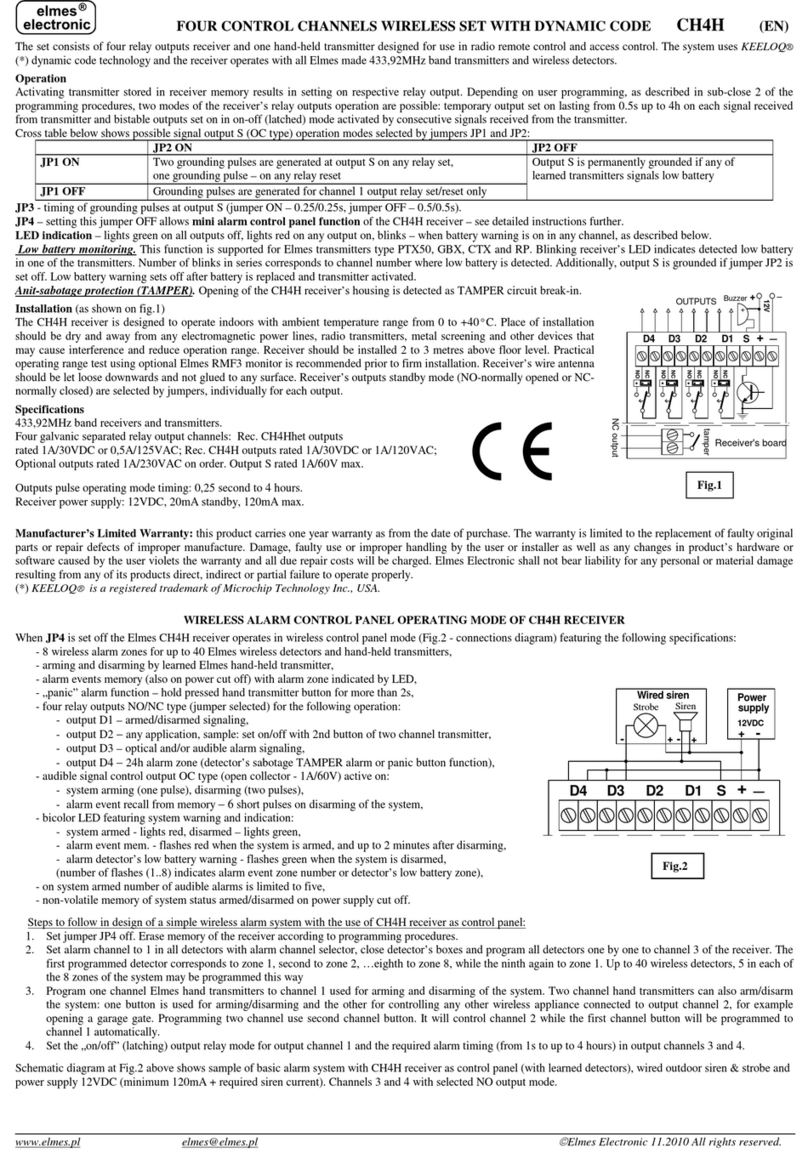
operation range. Factory outputs setting is NC (normally closed). Setting relay outputs to NO is made by solder
joints made for each relay on pc board soldering side. Disconnecting receiver’s power supply or opening its case
sets off output channel 20 indicating sabotage alarm (TAMPER).
PROGRAMMING PROCEDURES
Programming is performed with front panel taken off and the use of programming switches PRG (small switch with PRG marked on pcb) and BAT (front panel
illuminated switch marked LOW BATTERY CH.). Programming stages are indicated by red LED in middle-top section of the receiver.
1. Learning transmitter(s) (wireless detectors or keyfobs) to receiver's memory (maximum 60) follow steps as below:
a) Press shortly receiver's PRG switch. The PRG LED switches off and on and the first channel indication LED illuminates.
b) By shortly pressing the PRG switch select the required channel for learning transmitter.
c) Shortly press the BAT switch –the LED will switch off,
d) Depending on type of programmed transmitter proceed with next step as follows:
- hand transmitters (keyfobs) –double press the transmitter’s button (as in example 1) respective to required control channels.
- PTX50 detector (in TEST mode) –actuate two transmissions by moving hand in front of the detector (as in example 2).
- CTX3H, CTX4H wireless detectors –actuate two transmissions by double moving magnet in and out of case reed relay side or opening door/window if installed.
- RP501 transmitter - set the required mode of operation in transmitter (radio link testing mode not allowed), couple all inputs to ground and actuate transmission
+
120 S
Receiver's board
_
12V (750mA)
+
_
Buzzer 12V
Relay's outputs
solder joints
.....
....
Power supplay
