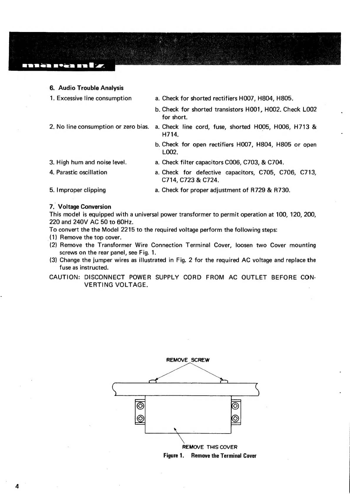
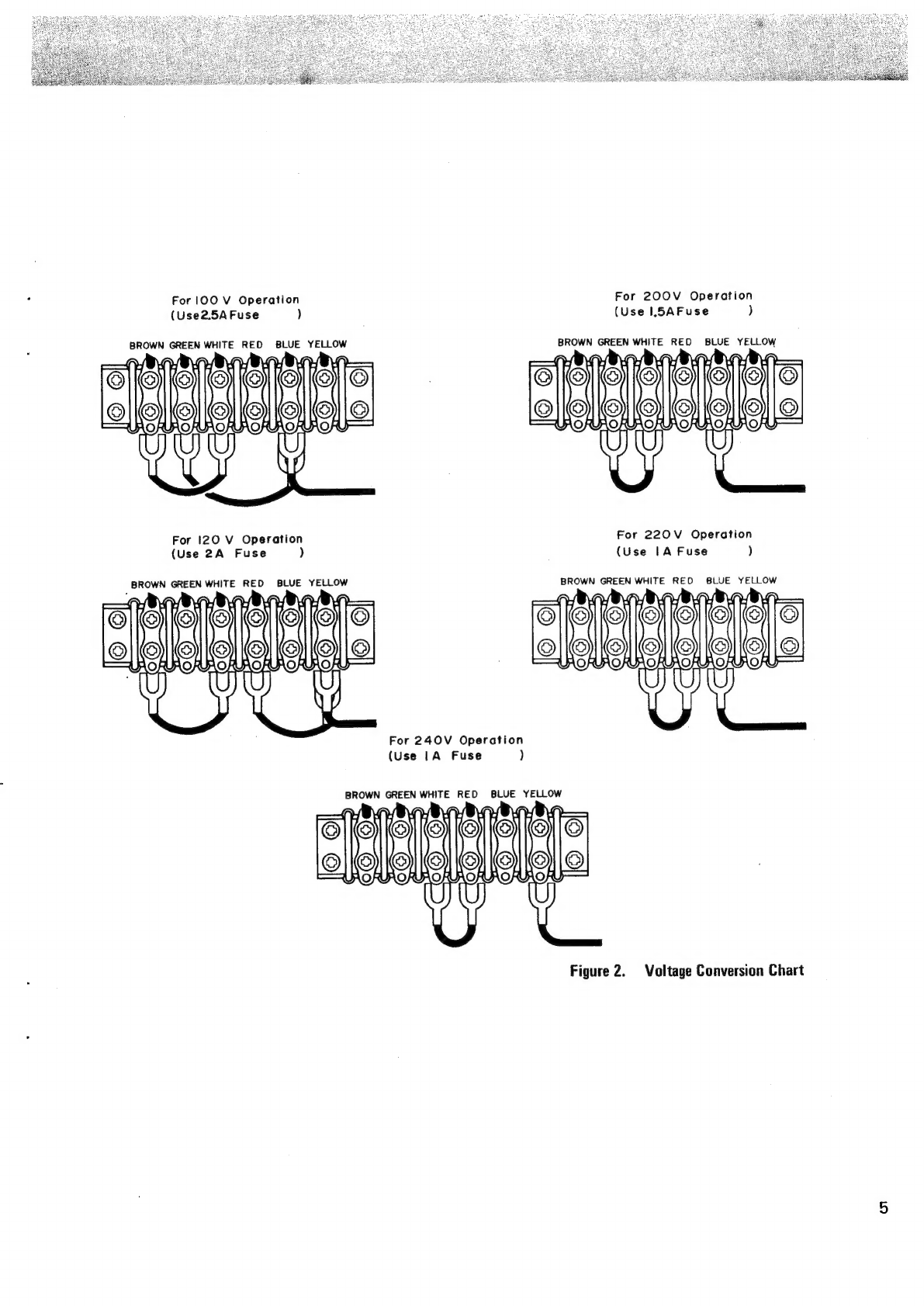
Marantz 2215 User manual

SERVICE
MANUAL
:
-
a
;
AUS
PIN
mo
=
a
id
me
cL
L
i
is
AEN
—_
EA
aN
U4
Sa
L
AEN.
HO
+
model
2215
s
BY
U4
4
AY.
—
BS td
SS
ta
a
=
ze
AYN
ays
—
*
BY
U4
-
=

EEeBen
nea
un
fz.
TABLE
OF
CONTENTS
SECTION
PAGE
INtrOCUCTION
25S
ie
oie
hee
eo
he
NS
BREN
as
Ste
bE
Lal
Slaw
Be
1
Service
Notes
.......
ccc
ccc cee
eee
en
eee
ee
eee
tee
eee
eee
nee
e
eet
eeane
1
FON
Ba
RC
=|
eee
eo
ae
ee
ne
1
EM
TUNE
sco icu
bas
ha
ete
Se
CE
eee
ae
ee
LAN
Sw
PERERA
Swe
eS
iy.
-
3
Phono
and
Pre-amplifier
.....
0...
cece
eee
eee
eee
teen
ee
ete
eeee
3
Main
Amplifier
.......0.
0
eee
ence
ee
eee
t
tence
e
enone
ee
aeeenee
3
Audio
Trouble
Analysis.
6c
on56%
bd
skeen
eee
rece
eee
ne
ee eg
Wales
eae
eee
3
Voltage
Conversion.
é
5
6i:v6
ened
avs eae
ketes
eee
eS
di
6
CES
EASA
Oe
aE
Ree
ee
4
Test
Equipment
Required
for
Servicing
.........
2.00
cece
reece
eee
ee
eee
ene
6
AM
Alignment
Procedure
..........-
0c
cece
eee
eee
eee
ee
ete
cence
eee
nenees
7
FM
Alignment
Procedure
........-.
0.
eee
ee
cece
tent
ee
cece
nese
ete
eterna
7
Stereo
Separation
Alignment
...........
ccc
eee
cee
ee
eee
teen
eee
eee
eens
8
Muting
Threshold
Adjustment
......
0.00:
eee
e
eee
ee
eee
teen
eee
eee
eeaee
8
Audio
Adjustment
........0
00
ccc
eee
ete
ee
eee
eee
ee
tener
ee
ee
eneenes
8
Parts
LiSt:s¢
odes
dod
Soccer
seta
Soaie
vata
ea
unsele
Ow
wh
pom ace
wd
Cee
eho
areey
aes
te
verdoaane
haw
alana
tae
17
SpeCitiCatiOns:
<.cs
s-05's'a.y
ce
Pie
Vos
Sse
aerate
eee
te
es
Sola
tiered
awa
ee
eee
wa
Ree
24
LIST
OF
ILLUSTRATIONS
FIGURE
NO
PAGE
1.
Remove
the
Terminal
Cover
...........00.eeeeeues
Polis
ateishins
Weta
aia,
ie
aehalee
4
2.
Voltage
Conversion
Chart
......
0.
cece
cece
ete
tence
nee
eee
ee
eee
erene
5
3.
Dial
Stringing...
......
0.0
eee
cece
ee
ee
ee
eee
ees
ee
Ne
eee
eT
8
4.
Front
Panel
Adjustment
and
Component
Locations
...............0
eevee
9
5.
Main
Chassis
Component
Locations
(Top
View)
............0eeeee
cece
eeeee
9
6.
Rear
Panel
Adjustment
and
Component
Locations
...........0.020
0
cece
eens
10
7.
Main
Chassis
Component
Locations
(Bottom
View)
..............0+65
sai
bratguieiet
10
8.
FM
Front
End
and
AM
Tuner
Assembly
P100
Component
Locations
.........-:
11
9.
FM
IF
Amplifier
and
Detector
Unit
Assembly
P200
Component
Locations
.....-.
11
10.
Muting
Control
and
Meter
Amplifier
Unit
Assembly
P300
Component
Locations...
12
11.
MPX
Stereo
Decoding
Amplifier
P400
Component
Locations
............+++6:
12
12.
Phono
Amplifier
Assembly
P900
Component
Locations
............2
0008
e
eee
13
13.
Tone
Amplifier
Assembly
P500
Component
Locations
.............0
ce ee
eee
13
14.
Tone
Control
Volume
Unit
Assembly
P650
Component
Locations...........--:
14
15.
Power
Amplifier
Assembly
P700
Component
Locations
............0
eee
eres
14
16.
Power
Supply
Assembly
P800
Component
Locations
..............0
ee
ee
eeee
15
17.
Loudness,
Muting,
High
and
Low
Filter
Switch
Unit
Assembly
P600
Component
Locations
..........
00.
c
ee
cece
ete
eee
eee
eee
nnn
15
18.
Schematic
Disdram
4.044
5.4%
082
a8 os
Pe
chided
a
tag
tans
aeed
ores
Re
Ree
ews
16

INTRODUCTION
This
service
manual
was
prepared
for
use
by
Authorized
Warranty
Stations
and
contains
service
information
for
Marantz
Model
2215
Stereophonic
Receiver.
Servicing
information
and
voltage
data
included
in
this
manual
are
intended
for
use
by
the
knowledgeable
and
experienced
technician
only.
All
instruction
should
be
read
carefully.
No
attempt
should
be
made
to
proceed
without
a
good
understanding
of
the
operation
in
the
receiver.
The
parts
list
furnish
information
by
which
replacement
part
may
be
ordered
from
the
Marantz
Company.
A
simple
description
is
included
for
parts
which
can
be
usually
be
obtained
through
local
suppliers.
1.
Service
Notes
As
can
be
seen
form
the
circuit
diagram
the
chassis
of
Model
2215
consists
of
the
following
units.
Each
unit
mounted
on
a
printed
circuit
board
is
described
within
the
square
enclosed
by
a
bold
dotted
line
on
the
circuit
diagram.
1.
FM
Front
End
&
AM
Tuner
..
0...
ee
eee
mounted
on
P.C,
Board,
P100
2.
FMIF
Amplifier
and
Detector
Unit
........-....5555-
mounted
on
P.C.
Board,
P200
3.
Muting
Control
and
Meter
Amplifier
Unit
.............
mounted
on
P.C.
Board,
P300
4.
MPX
Stereo
Decoding
Amplifier
..........2...00000-
mounted
on
P.C.
Board,
P400
5.
Phono
Amplifier...
2...
ee
eee
mounted
on
P.C.
Board,
P900
6.
Tone
Amplifier
cso
cae
ao
Fs
eT
O
Ee
Ee
eS
mounted
on
P.C.
Board,
P500
7.
Tone
Control
Volume
Unit...
0...
2.0002
eee
ee
eee
mounted
on
P.C.
Board,
P650
8.
Power
Amplifier...
2.0...
ce
ee
es
mounted
on
P.C.
Board,
P700
©:
Power
Supp
de!
Grseanin
gw
aan
aie
eiere
i
ee
ware
ka
ea
mounted
on
P.C.
Board,
P800
10.
Loudness,
Muting,
High
and
low
Filter
Switch
Unit
.......
mounted
on
P.C.
Board,
P600
2.
AM
Tuner
All
components
except
Tuning
capacitor
and
ferrite
bar
antenna
are
mounted
on
a
printed
circuit
board
P
100.
The
AM
signals
induced
in
a
ferrite
bar
antenna
are
applided
to
the
base
of
Mixer
transistor
H102
through
a
capacitor
of
C109,
while
the
local
oscillator
voltage
is
injected
to
the
emitter
of
H102
through
the
capacitor
C157.
Both
AM
signals
and
oscillating
voltage
are
mixed
at
the
base-emitter
junction
and
converted
into
455
KHz
intermediate
frequency.
The
resulting
IF
signal
is
applied
to
the
first
IF
transformer
F101
consisting
of
one
ceramic
filter
and
two
tuned
circuits.
The
output
of
F101
is
led
to
the
transistor
H103
which
in
turn
apply
its
output
to
the
transistor
of
next
stage
H104.
The
fully
amplified
IF
output
is
then
applied
to
the
diode
H107
to
detect
audible
signal
through
the
detector
transformer
L102.
The
detected
audio
signal
is
filtered
and
amplified
and
the
final
audio
output
is
obtained
from
the
collector
of
H105
and
applied:
one
to
the
tape out
jacks
through
monitor
switch
on
the
front
panel
and
the
other
to
the
function
rotary
switch.
The
DC
component
of
the
detected
IF
signal
is
used
as
a
AGC
voltage
to
control
emitter
current
of
H103
and
H102
through
the
resistor
R112
and
R106
respectively.
A
part
of
IF
signal
output
is
also
applied
to
the
diode
H108
through
a
capacitor
C123
and
rectified
to
obtain
DC
current
for
energizing
the
AM
signal
strength
meter
MOO1.

3.
FM
Tuner
The
FM
Tuner
section
of
Model
2215
is
divided
into
three
functional
blocks:
FM
front
end,
IF
amplifier
&
Detector,
Muting
control]
and
MPX
stereo
decoding
circuit.
FM
signals
induced
on
a
FM
antenna
are
led
to
FM
antenna
coil
L103.
These
signals
are
then
applied
to
the
FET
RF
amplifier
which
in
turn
applies
its
output
to
the
next
Transistor
Mixer
H111
through
a
high-Q
tuned
circuit.
‘The
Mixer
convert
its
input
signal
into
10.7MHz
intermediate
frequency
and
amplifies
it.
The
H110
is
a
local
oscillator
and
its
output
is
injected
into.
the
base
of
Mixer
transistor,
the
injection
voltage
is
about
100
to
200mV.
The
10.7MHz
front
end
IF
output
is
led
to
the
next
IF
amplifier
unit
through
a
coaxial
cable.
The
IF
amplifier
unit
consists
of
five
stages
of
IF
amplifiers.
Two
pieces
of
ceramic
filters
are
used
to
obtain
high
selectivity
a
pair
of
symmetrical
diode
limiter
is
also
employed
for
the
best
limitting
characteristics,
improved
capture
ratio
and
good
AM
suppression.
A
part
of
IF
amplifier
H202
is
rectified
by
the
diodes
H206
and
H207
and
its
DC
output
is
fed
back
to
the
gate
of
FET
RF
amplifier
to
decrease
the
gain
of
it
with
increased
input
signal
strength.
3-1
Muting
and
Auto-Stereo
Switching
Circuits
The
muting
circuit
consisting
of
all
solid-state
electrical
switching
has
been
incorporated
in
the
Model
2215.
The
DC
voltage
obtained
by
rectifing
a
part
of
IF
output
signal
from
the
H204
is
applied
to
the
base
of
H304
and
turns
on
it,
if
the
IF
output
is
greater
than
predetermined
level
(muting
threshold
level).
When
the
H304
is
turned
on,
the
H305
is
turned
off,
thus
allowing
the
_
emitter-collector
resistance
of
the
H305
increasing
and
the
collector
voltage
rises
about
8V.
The
increased
collector
voltage
increases
the
base
bias
voltage
and
makes
the
switching
transistor
H306
turn
on,
thus
decreasing
the
collector-emitter
resistance
to
near
zero
ohm
and
allowing
the
power
supply
path
to
the
IC
closed.
When
the
input
signal
is
lower
than
the
predetermined
level,
the
DC
output
obtained
is
small
and
can
not
turn
on
the
H304,
thus
the
H304
keeps
its
turn-off
state
and
this
makes
H305
turn
on,
decreasing
the
collector
voltage
and
turning
off
H306.
Thus
no
power
is
supplied
to
the
IC
H205
and
signals
below
the
threshold
level
are
muted
out.
The
muting
threshold
level
can
be
varied
by
adjusting
the
trimming
resistor
R306.
The
DC
voltage
developed
at
the
collector
of
H305
is
also
used
to
make
the
Auto-Stereo
switching
transistor
H403
turn
on
and
off.
3-2
MPX
Stereo
Decoding
Circuit
Non-equalized
audio
signals
are
applied
to
the
first
amplifier
H401
which
servs
as
a
tuned
amplifier
for
the
pilot
signal
in
the
composite
signals
and
as
a
buffer
amplifier
for
the
rest
audio
signals.
The
amplified
19KHz
pilot
signal
is
led
to
the
second
19KHz
amplifier
H402
and
further
amplified
if
switching
transistor
H403
is
turned
on
by
the
controlling
DC
signal
as
descibed
above.
The
19KHz
pilot
signal
is
rectified
by
the
doubler
circuit
consisting
of
H412
and
H413
to
obtain
synchronized
38KHz
signal
to
drive
the
H404.
The
H404
is
the
38KHz
tuned
amplifier
and
supplies
its
output
to
the
switching
matrix
circuit
consisting
of
four
diodes.
The
composite
signals
are
applied
to
the
center
tap
of
switching
transformer
L402-2
and
decoded
into
left
and
right
channel
signals,
then
both
channel
signals
are
led
to
the
crosstalk
cancelling
amplifier
wh
ich
utilizes
complementary
confuguration
with
NPN
and
PNP
transistors
through
de-emphasiss
net
works.
Transistors
H313
and
H314
are
buffer
amplifiers
and
their
outputs
are
led
to
the
function
switch.

3.3
Suggestion
for
Trouble
Shooting
of
FM
Tuner
3.3.1
Symptom:
No
FM
Reception
First
turn
ON
the
power
switch
and
try
to
tune
FM
stations.
Rotate
the
fly-wheel
tuning
knob
slowly
and
observe
the
FM
tuning
meter.
If
the
meter
deflect
at
several
frequencies
received,
the
circuits
preceding
the
IF
amplifier
H204
may
have
no
failure.
When
no
reading
is
obtained
in
the
meter,
check
FM
local
oscillator
circuit,
using
a
RF
VTVM.
The
normal
local
oscillator
voltage
is
one
or
two
volts
(rms)
at
the
tuning
capacitor,
depending
on
the
tuning
capacitor
position.
If
the
local
oscillator
voltage
is
normal,
next
check
all
voltage
distributions
in
the
FM
circuits
and
compare
them
with
those
shown
in
the
circuit
diagram.
When
the
tuning
meter
deflects
but
no
sound
is
obtained,
check
audio
circuits,
using
a
high
sensitive
oscilloscope.
3.3.2
Symptom:
No
Stereo
Separation
First
check
the
“MONO”
switch
is
in
normal
out
position.
Connect
a
FM
RF
signal
generator
output
modulated
by
a
stereo
modulator
to
the
rear
FM
antenna
terminals,
and
check
the
stereo
beacon
is
turned
on
or
not.
If
not
turned
on,
check
for
19
KHz
pilot
signal
and
38
KHz
switching
signal,
using
an
oscilloscope.
4.
Phono
and
Pre-amplifier
Signals
from
the
tuner
and
AUX
jacks
are
applied
to
the
selector
switch.
Signals
from
the
PHONO
jacks
are
applied
to
the
phono-amplifier
consisting
of
transistor
r'901,
H903
and
H905.
The
gain
of
the
amplifier
is
40
dB.
The
amplified
and
equalized
phono-signals
are,
then,
fed
to
other
section
of
the
selector
switch
which,
in
turn,
applies
output
signals
from
the
tuner,
phono-amplifier
and
AUX
jacks
to
the
TAPE
MONITOR
switch
and
TAPE
OUT
jacks.
The
TAPE
MONITOR
switch
applies
the
signals
to
the
balance
and
volume
controls.
The
controlled
signals
are
fed
to
the
pre-amplifier
consisting
of
H501,
H503
and
H505.
Frequency
response
of
the
amplifier
can
be
varied
by
BASS
and
TREBLE
controls.
The
controlled
output
are
then
led
to
the
main
amplifier
through
high
and
low
pass
filter
push-switches.
5.
Main
Amplifier
Transistor
H701
is
a
pre-driver
coupled
to
the
transistor
H703
through
capacitor
C711.
Transistor
H703
drives
the
inverter
transistors
H709
and
H710
which,
in
turn,
drive
the
power
stage
consisting
of
HOO1
and
HOO2.
Transistors
H705
and
H709
are
current
limitters
and
operate
as
power
protecting
circuits.
Excessive
currents
flowing
into
the
power
stage
are
detected
by
the
resistors
R741
and
R745
and
the
resultant
variations
are
applied
to
the
transistors
H705
and
H707
and
make
them
turned
on.
This
decreases
the
current
flowing
into
the
H709
and
H710.
In
this
way
the
currents
flowing
in
the
power
stage
(HOO1
and
HO02)
are
restricted
within
a
safe
value.

nEeRen
Beam
unl
-z.
6.
Audio
Trouble
Analysis
1.
Excessive
line
consumption
a.
Check
for
shorted
rectifiers
HOO7, H804,
H805.
b.
Check
for
shorted
transistors
HOO1,
HOO2.
Check
L002
for
short.
2.
No
line
consumption
or
zero
bias.
a.
Check
line
cord,
fuse,
shorted
HOO5,
HOO6,
H713
&
H7
14.
b.
Check
for
open
rectifiers
HOO7,
H804,
H805
or
open
Lo02.
3.
High
hum
and
noise
level.
a.
Check
filter
capacitors
C006,
C703,
&
C704.
4.
Parastic
oscillation
a.
Check
for
defective
capacitors,
C705,
C706,
C713,
C714,
C723
&
C724.
5.
Improper
clipping
a.
Check
for
proper
adjustment
of
R729
&
R730.
7.
Voltage
Conversion
This
model
is
equipped
with
a
universal
power
transformer
to
permit
operation
at
100,
120,
200,
220
and
240V
AC
50
to
60Hz.
To
convert
the
the
Model
2215
to
the
required
voltage
perform
the
following
steps:
(1)
Remove
the
top
cover.
(2)
Remove
the
Transformer
Wire
Connection
Terminal
Cover,
loosen
two
Cover
mounting
screws
on
the
rear
panel,
see
Fig.
1.
(3)
Change
the
jumper
wires
as
illustrated
in
Fig.
2
for
the
required
AC
voltage
and
replace
the
fuse
as
instructed.
CAUTION:
DISCONNECT
POWER
SUPPLY
CORD
FROM
AC
OUTLET
BEFORE
CON-
VERTING
VOLTAGE.
REMOVE
SCREW
REMOVE
THIS
COVER
Figure
1.
Remove
the
Terminal
Cover

For
|OO
V
Operation
For
200V
Operation
(Use2.5A
Fuse
)
(Use
|.S5AFuse
)
BROWN
GREEN
WHITE
RED
BLUE
YELLOW
BROWN
GREEN
WHITE
RED
BLUE
YELLOW
For
120
V
Operation
For
220V
Operation
(Use
2A
Fuse
)
(Use
1A
Fuse
)
BROWN
GREEN
WHITE
RED
BLUE
YELLOW
BROWN
GREEN
WHITE
RED
6LUE
YELLOW
For
240V
Operation
(Use
|A
Fuse
)
BROWN
GREEN
WHITE
RED
BLUE
YELLOW
Figure
2.
Voltage
Conversion
Chart

Peper
ne
be:
Bs
tw
4
9.
Test
Equipment
Required
for
Servicing
Table
1
lists
the
test
equipment
required
for
servicing
the
Model
2215
Receiver.
Manufacturer
and
Model
No.
AM
Signal
Generator
Test
Loop
FM
Signat
Generator
Stereo
Modulator
Audio
Oscillator
Oscilloscope
VTVM
Circuit
Tester
AC
Wattmeter
AC
Ammeter
Line
Voltmeter
Variable
Autotransformer
(0-140VAC,
10
amps.)
Shorting
Plug
Output
Load
(8
ohms,
0.5%,
100W)
Output
Load
(4
ohms,
0.5%,
100W)
Less
than
0.3%
distortion
Less
than
0.3%
distortion
Weston
Model
CVO-100P,
less
than
0.02%
residual
distortion
is
required.
High
sensitivity
with
DC
hori-
zontal
and
vertical
amplifiers.
With
AC,
DC,
RF
range
Simpson,
Mode!
390
Commercial
Grade
(1-10A)
Commercial
Grade
(0-150VAC)
Powerstat,
Model
116B
Use
phono
plug
with
600
ohm
across
center
pin
and
shell.
Commercial
Grade
Commercial
Grade
Signal
source
for
AM
align-
ment
Used
with
AM
Signal
generator
Signal
source
for
FM
align-
ment
Stereo
separation
alignment
and
trouble
shooting
Sinewave
and
squarewave
sig-
nal
source.
Waveform
analysis
and
Trou-
ble
Shooting,
and
ASO
align-
ment.
Voltage
measurements.
Trouble
Shooting
Monitors
primary
power
to
Amplifier.
Monitors
amplifier
output
un-
der
short
circuit
condition.
Monitors
potential
of
primary
power
to
amplifier
Adjusts
level
of
primary
power
to
amplifier.
Shorts
amplifier
input
to
elimi-
nate
noise
pickup.
Provides
8-ohm
load
for
am-
plifier
output
termination.
Provides
4-ohm
load
for
am-
plifier
output
termination.

9.
AM
Alignment
Procedure
AM
IF
Alignment
1.
2.
Connect
a
sweep
generator
to
the
J102
and
an
alignment
scope
to
the
capacitor
C125,
Rotate
each
core
of
IF
transformer
F101
and
L102
for
the
maximum
height
and
flat
top
symmetrical
response.
AM
Frequency
Range
and
Tracking
Alignment
1.
2.
6.
Set
AM
signal
generator
to
525
KHz.
Turn
the
tuning
capacitor
fully
closed
(place
the
tuning
pointer
at
the
low
end.)
and
adjust
the
oscillator
coil
L101
for
maximum
audio
output.
Set
the
signal
generator
to
1650
KHz.
Place
the
tuning
pointer
in
the
high
frequency
end and
adjust
the
trimming
capacitor
C155-2
for
maximum
audio
output.
.
Repeat
step
1
and
2
until
no
further
adjustment
is
necessary.
.
Set
the
generator
to
600
KHz
and
tune
the
receiver.to
the
same
frequency
and
adjust
a
slug
core
of
AM
ferrite
rod
antenna
for
maximum
output.
.Set
the
generator
to
1400
KHz
and
tune
the
receiver
to
the
same
frequency
and
adjust
the
trimming
capacitor
C155-1
for
maximum
output.
Repeat
the
procedure
4
and
5
until
no
further
adjustment
is
necessary.
Note:
During
tracking
alignment
reduce
the
signal
generator
output
as
necessary
to
avoid
AGC
action.
10.
FM
Alignment
Procedure
1.
2.
Connect
a
FM
signal
generator
to
the
FM
antenna
terminals
and
a
oscilloscope
and
an
audio
distortion
analyzer
to
the
tape
output
jack
on
the
rear
panel.
Set
the
FM
SG
to
87.5
MHz
and
provide
about
3
to
5uV.
Place
the
tuning
pointer
at
the
low
frequency
end
by
rotating
the
tuning
knob
and
adjust
the
core
of
oscillator
coil
L106
to
obtain
maximum
audio
output.
.
Set
the
FM
SG
to
108.5
MHz
and
provide
about
3
to
5uV.
Rotate
the
tuning
knob
and
place
the’
tuning
pointer
at
the
high
frequency
end
and
adjust
the
trimming
capacitor
C152
for
maximum
output.
.
Repeat
the
step
2
and
3
until
no
further
adjustment
is
necessary.
.Set
the
FM
SG
to
90
MHz
and
tune
the
receiver
to
the
same
frequency.
Decrease
signal
generator
output
until
the
audio
output
level
decreases
with
the
decreasing
generator
output.
Adjust
the
RF
coil
L104
and
antenna
coil
L103
and
IF
transformer
L105
for
minimum
audio.
distortion.
.
Set
the
FM
SG
to
106
MHz
and
tune
the
receiver
to
the
same
frequency.
Decrease
the
signal
generator
output
until
the
audio
output
level
decreases
with
the
decreasing
generator
output.
Adjust
the
trimming
capacitor
C155-3
and
C155-4
for
minimum
distortion.
.
Repeat
the
step
5
and
6
until
no
further
adjustment
is
necessary.
.
Connect
a
DC
VTVM
with
1
V
range
selected
across
the
capacitor
C277
and
adjust
the
secondary
core
(black)
of
discriminator
transformer
L201
so
that
no
voltage
reading
is
obtained
on
the
VTVM
at
no
signal.
Next
set
the
FM
SG
to
98
MHz
and
increase
the
output
level
1
KuV,
then
tune
the
receiver
to
the
same
frequency
so
that
no
deflection
is
obtained
on
the
VTVM.
Adjust
primary
core
(pink)
of
L201
for
minimum
distortion.

metas
Bean
ne
i
-z.
11.
Stereo
Separation
Alignment
1.
4.
Set
the
FM
SG
to
provide
1
KuV
at
98
MHz.
Tune
the
receiver
to
the
same
frequency
so
that
the
VTVM
connected
to
the
C227
will
give
no
readings.
.
Modulate
the
FM
SG
with
67
KHz
audio
frequency.
Connect
a
oscilloscope
to
the
R413.
Adjust
the
core
of
L403
for
minimum
height
of
the
67
KHz
signal
on
the
scope.
.
Modulate
the
FM
SG
output
with
stereo
composite
signal
consisting
of
subchannel
signal
only
(of
course
a
pilot
signal
must
be
included.).
Adjust
the
core
of
L410
for
maximum
audio
output,
then
modulate
the
signal
generator
output
with
a
stereo
composite
signal
consisting
of
L
channel
signal
only
and
again
adjust
the
core
of
L401
for
maximum
audio
output.
Adjust
the
trimming
resistor
R428
for
maximum
and
same
separation
in
both
channels.
12.
Muting
Threshold
Adjustment
1.
Set
the
FM
SG
output
to
provide
12.5uV
(IHF)
at
98
MHz
and
tune
receiver
to
the
same
frequency.
Adjust
the
trimming
resistor
R306
for
the
threshold
level
of
12.5uV.
(During
this
adjustment
turn
the
MUTING
push-switch
“‘on”’.)
13.
Audio
Adjustment
1.
Connect
a
VTVM
across
the
resistor
R747
and
adjust
the
trimming
resistor
R729
until
the
VTVM
reads
7.5mV
DC.
For
the
other
channel
connect
the
VTVM
across
the
R748
and
adjust
the
R730
for
the
same
reading.
.
Connect
a
oscilloscope
across
the
speaker
terminals.
Apply
an
audio
signal
of
1
KHz
to
the
AUX
jacks
and
increase
the
audio
signal
until
the
audio
output
on
the
scope
begin
to
start
clipping.
Adjust
the
trimming
resistor
R723
for
equal
and
symmetrical
clipping.
For
the
other
channel
adjust
the
R724.
POINTER
Figure
3.
Dial
Stringsng

MOO!
SO02-I
$002-2
S6OI-I
SEOI-2
S6OI-3
S60I-4
S003-2
$003-I
TUNING
KNOB
weflector
These
ty
bbls
baklace
voli
pene,
JOO6
sool
R655
R656
ROOS
ROO4
S004
Figure
4.
Front
Panel
Adjustment
and
Component
Locations
PIOO
P200
P300
LOO2
P400
Figure
5.
Main
Chassis
Component
Locations
(Top
View)

10
Wool
JO0O4
JOO5
ROOW
MAX
TOTALE
GOW
Max
TOTAL
JOIO
=9y009
JOO8
Figure
6.
Figure
7.
LOO!
JOO!
ss58)
GASUNS.
JOO3
JO02
Rear
Panel
Adjustment
and
Component
Locations
003
Main
Chassis
Component
Locations
(Bottom
View)

Hill
C144
Cci4l
HIIO
Ci39
R133
Figure
8.
FIM
Front
End
and
AM
Tuner
Assembly
P100
Component
Locations
Figure
9.
¢229
=
¢230
oS
Ts
:
£9
FM
IF
Amplifier
and
Detector
Unit
Assembly
P200
Component
Location
11

Figure
10.
Muting
Control
and
Meter
Amplifier
Unit
Assembly
P300
Component
Locations
H406
H408
R405
H40l
C434
R462
Figure
11.
MPX
Stereo
Decoding
Amplifier
P400
Component
Locations
12

2
pas
18
‘Wo
H90I
C907
H903
R907
J904
y908
J906
ome}
R908
be
ca
oH
-J907
909
y9I0
c908
H984
H906
Figure
12.
Phono
Amplifier
Assembly
P900
Component
Locations
Figure
13.
Tone
Amplifier
Assembly
P500
Component
Locations
13

14
O—d00TSBsay
SqY4
Low
Gott
oO
CA
xia
fed
ca
‘T
Figure
15.
Power
Amplifier
Assembly
P700
Component
Locat
ons

su01}e907
JUaUOdWOD
YONG
Ajquiassy
wu)
YaUMS
Ja}}14
Moz
pue
YyBIy
gOo99
¢099
0-l00ei8SAv
$U01Ve907]
JUBUOdWOX
ON8d
Ajquiassy
Ajddng
samog
“gt
ainhly
0-—-OO0C8SaY
OQ
stwanam
‘funny
4
ssaupnoy
“/1
anbi4
~099
TE

16
f
H101,
102
HI03,104
HIOS
HIO09
HHO,
1
P100
HT309411B
HT3037210
HT3064418
HDIO00I05
HF200191A
HT308291B
|
2SC9410
286372
2sce44s
IN
60
2SKI9Y
2S8C829B
R143
C109
Fol
|
HIO!
ee
lee
scncer
HIO2
-
HIO3
Zi
Ea:
FILTER
|
Lio
cigs
390PF
J102
a‘
O
3
Iciss-1
ciss-2
FM
|
jf
R102)
ci06
RUS)
RUT
21031,
3.3K
20PF|
15K{
18K
5
2
=
&
&
a
8
g
=
=
Loo!
C132
R128
Ole
33K
Lh
nye
lcs
pee
cC-o-OCo
OCrO
re
Oro
or
H90I~
904
905,906
=]
$001
-2R
S00!
-iF
+
|
P900
HT3100024
HT304560R
|
°
Spr
|
2SC1000Gr.
BL
2SC458LG
A
B
on,
ees
%
|
moor
|
&¥
w—O>
D
Jo02
H905
>
=
col7
aIyF
SOV
5906
PHONO
O
L
R907|
|
Mo02
R
100K
Jo19
(Ee)
H205
206,207,210
~
213
H208
,209
HCIOOOIOS
HDIOOOIOS5
HD2001105
TATO60P
IN6O0
1$
1555
209
R227
C222
.OlWF
150
OlpF
©)
c2iz
|
R226
-O1F
|
150
R230:
Kl
R225
R229
K
H208
100K
c2i6|
H209]
C220]
c2ai
100P
OlpF]
Oly
R26
C210
C2il
RzB
100
1OpF
04
yF
100
16V
H301
HT308291B
2S8C8298
R237
R239
H210
gao
H
302,303,307
H304
H305,306
501,502
HDIOOOI05 HT307331C
HT
3037310
P
500
5
HT304580Z
IN60
2S8C7336
2S8C
373
l
2SC458LG
D
RuS
150K
H503~506
HT304580Y
2SC458LGC
R235
C231
YOK
10pF
6.8K
16v
;
‘al
O
R523,
33K
|
O
ISU
AUX
16v
1K
JO13_MOOS
°
Colo!”
2PS30)
"|
C99.
vane
—————————
4TyF
10K,
100pF
MONITOR
Jiev
;
50V
a
|
R
wee
a
;
TS
Hl
ence
Ll
1ROO4
S60I-1
c
|
ir!
SS
2
Roz
BOS,
|
R604
TAPE
56
C3)
|
6.8K
+|
100
pF
["j
ee
JOI8_MOIO
|
B03
ny
>}
S808
p
50V
be
moos
@
1]
S30pF
ge
«R806
47
pF
re
000
—
—O
50V
33K
7
Sov
P8000
LOUDNESS
REIa RGIS
Joo3
mooa
@
J]
|
|
Sox
Soe
ads
a
9
=
|
B02
"804,805,
808
4806
.
eR
PETER:
L
HT312
1324
4D2000413
—_
HD3002209
Seotne
2SCi213
AB
orC
S1B-O01-02
82-120
ie
joa
eee
ee
O
murine
cco
fe
er er
er
re
eee
Oe
rn
a
ar
a
a
OC
O_O
_
Seale
H40i~404
W405
406
,
407
408,409
H410
411
H4120417
R425
Raat
R437
71
7
|
HT3037210
HT30733iC
HT307322A
HT1049424
HT306441C
HDIOOOIOS
2M
22K
1K
|
1007
120/
200/
220/
240VA
28C372
2SC
7336
2SC732
Bl
or
Gr
=.
2S
A494
Gr
or
Y
2Sc644T
IN60
H406:
H408:
Foor
50~60
Hz
|
fy’
jy
|
TRANSISTOR
CONNECTION
H
Uy
uN
tout
(BOTTOM
VIEW)
ae
H4I4
R414
es
Sasa
ibs
we
||
a
eS
a
|
Rael
v7,
Lao2-1
ie
Lao2-2
10K
.
at
+
[
H701,
702
H
703,704
HTO5
,706
H707,708
W713,
714
H715~718
7
HOOl~004
O
4
KS)
a
K)
R435
+]
Cal6
HT309452A
HT308532A
HT303711B
HT105621B
HVO000705
=
HDIOO0
105
HKO3I5I9A
yaor
oT
NSS
Raze:
Resse
108.
OMe.
|
Hol
~
108
280945
Q,R
2SC853M.L
28C3710
2SA562
S3016R
IN6O
c401
IK
15K
tev
250315
DorE
|
ag
tol
Soe
H709
~712
16V
~
4
bag
°
‘oe
Rae
#
|
Hasecaee
HKOGO6I9A
|
H413 R410
H4I6
R49
3
H40I~
411
2SC959
N.M,L
HOOS,006
aos
27K
K)
10K
|
2SA606
N.M.L
K)
Hvoo0C—O2
12
|
C406
gh"
Ss
EO!
iy sy
SV-3A
R40g
]
RaA04]
tour
9
Ratt
R440
|
co!
H501~
506
O
J402
470K]
|
1.5K
tev
|
1.2K
HT
5.6K
Bo!
HNOL~906
R741
|
R747
See
ie
1
HOO!
;
oe
eras
ESeunte
oo
E05
Ga
sn
oe
ed
ead
2.
Hu
es
ae!
220
EO
H7Ol
,
702
O
C407
R413,
sae
co!
H705~
708
404
4700PF
1.5K
BO}
H602
ATyF
RA53
|
tev
330
bole
°
R462
§
|
15K
|
|
220K
1°
a
of
&)
W703.
704
|
R459
ae
R461
ord
o8
MIRO
PLE
220K
15K
¥
|
e432 R452
|
P400
Rho
K
ey
pane
|
f--->
0.
ORAIN
sss
=
mn
;
“(408
“Vaor>
"ge
S532
Hall
2k
Se
8)
wee
ae
|
lev
G
=
GATE
ges
R730
C724.
8.2K
%
330
$470
1007
SPEAKER
SYSTEMS
L
Ro
MAIN
+
-
—
+
Joo
Figure
18.
Schematic
Diagram

REF.
MARANTZ
REF.
MARANTZ
|
DESIG.
PART
NO.
DESCRIPTION
DESIG.
PART
NO.
DESCRIPTION
281826250
|
Pulley
K
282140140
|
Frame
Assembly
281826251
|
Pulley
K
282106301
Escutcheon
257912001
insulator
281840101
|
Frame
141511801
|
Spacer
281815801
|
Window
257710602
|
Bearing
273125901
|
Bush
x
3
281905350
|
Cover
K
282105302
|
Cover
257816052
|
Bracket
K
281825905
|
Bush
x
9
145525901
|
Bush
x
2
281816006
|
Bracket
Front
Bracket
Assembly
Bracket
282116040
281816001
282126701
|
Heat
Sink
281811801
|
Spacer
281810104
{|
Support
x
4
282016007
|
Bracket
x
2
282116041
Rear
Bracket
Assembly
257711806
|
Spacer
x
4
282116002
|
Bracket
282026702
|
Heat
Sink
x
2
55060305F
|
T.R.
Rivet
x
6
281800450
|
Table
K
55060365F
T.R.
Rivet
x
4
282110901
Shield
x
3
YJ0400018
|
Jack,
AC
outlet
282112001
Insulator
Y¥J0400018
|
Jack,
AC
outlet
257905502
|
Collar
x
4
YT0304002
YT0304002
YT0208002
Terminal,
Push
type
4P,
SPK
Terminal,
Push
type
4P,
SPK
Terminal,
8P
282126901
{|
Protector
282126902
|
Protector
281810104
|
Support
x
4
281815401
|
Knobx
8
282116001
|
Bracket
281815402
|
Knob
282110101
|
Support
x
2
281815403
|
Knobx
5
282116003
|
Bracket
281825701
|
Lid
281915901
|
Drum
281825702
|
Lid
71101569M
|
Spring
257706302
|
Escutcheon
282010701
|
Sheet
257706303
|
Escutcheon
120225801
|
Hook
257727301
|
Fly
Wheel
273025901
|
Bush
x
4
282126501
|
Indicator
281912002
|
Insulator
138200503
|
Clamper
x
15
72081602A
|
String
x
120
281810701
|
Sheet
54010089R
|
Washer
281810301
|
Pointer
257711803
j
Spacer
x
4
281810302
|
Pointer
282111801
|
Spacer
281805301
|
Cover
282100501
}
Clamper
275905701
|
Legx
4
281927103
|
Holder
282130201
|
Dial
51570305B
|
P.H.
Tapt
Screw
x
8
282110550
|
Chassis
K
51570306B
|
P.H.
Tapt
Screw
x
6
282116002
|
Bracket
515703128
|
P.H.
Tapt
Screw
x
3
281816003
|
Bracket
281816004
|
Bracket
54050300R
51100306E
51040306A
T.L.
Washer
OR
x
2
B.H.M.
Screw
x
2
F.H.M.
Screw
x
2
281816051
|
Bracket
K
281805501
|
Collar
x
3
51640412D
|
Set
Screw
C.P
282127401
|
Reflector
54040402A
|
Spring
Washer
281927401
|
Reflector
53110403E
|
Hexagon
Nut
281827101
|
Holder
515704088
|
P.H.
Tapt
Screw
x
6
281927101
|
Holder
51570306B
|
P.H.
Tapt
Screw
x
4
281927102
|
Holder
51570306B
|
P.H.
Tapt
Screw
x
6
281805101
|
Guide
51042606S
|
F.H.M.
Screw
x
5
281816005
|
Bracket
281810650
|
Bearing
K
51570306B
51570306B
51570306B
P.H.
Tapt
Screw
x
3
P.H.
Tapt
Screw
x
3
Shaft
P.H.
Tapt
Screw
257811202
17

Pee
ts
Pay:
Be
D4
REF.
MARANTZ
DESIG.
PART
NO.
DESCRIPTION
REF.
MARANTZ
DESIG.
PART
NO.
DESCRIPTION
51570306B
51570306B
51650304D
53110403E
54060300R.
0824
51570306B
|
P.H.
Tapt
Screw
x
2
51570306B
|
P.H.
Tapt
Screw
x
4
53110603A
}
Hexagon
Nut
54040602A
|
Spring
Washer
54020601E
|
Flat
Washer
P
53110303E
|
Hexagon
Nut
*51100308S
|
B.H.M.
Screw
x
6
P.H.
Tapt
Screw
x
10
P.H.
Tapt
Screw
x
10
Set
Screw
H.P.
x
2
Hexagon
Nut
T.L.
Washer
IR
x5
56382540G
51100310S
53110303E
54050300R
Eyelet
B.H.M.
Screw
x
2
Hexagon
Nut
x
2
T.L.
Washer
OR
x
2
-
53110303E
51100306S
55060307F
54050300R
51100306S
51100306S
51100306S
51100306S
51100306S
51570312B
Hexagon
Nut
x
6
B.H.M.
Screw
x
2
T.R.
Rivet
x
4
T.L.
Washer
OR
x
4
B.H.M.
Screw
x
6
B.H.M.
Screw
x
3
B.H.M.
Screw
x
2
B.H.M.
Screw
x
2
B.H.M.
Screw
x
2
P.H.
Tapt
Screw
x
4
51100310S
54050300R
53110303E
54050400R
51122608E
51100406S
51100406S
54020401S
51570410B
54040402N
B.H.M.
Screw
x
2
T.L.
Washer
OR
x
2
Hexagon
Nut
x
2
T.L..Washer
OR
T.H.M.
Screw
x
4
B.H.M.
Screw
x
10
B.H.M.
Screw
x
4
Flat
Washer
P
x
4
P.H.
Tapt
Screw
x
4
Spring
Washer
x
4
54020401E
51570305B
51570306B
51100306S
51100308S
51570408B
53110403A
54020401A
51570408B
53110401A
Flat
Washer
P
x
4
P.H.
Tapt
Screw
x
8
P.H.
Tapt
Screw
x
4
B.H.M.
Screw
x
4
B.H.M.
Screw
x
2
P.H.
Tapt
Screw
x
4
Hexagon
Nut
x
4
Flat
Washer
P
x
4
P.H.
Tapt
Screw
x
4
Hexagon
Nut
x
4
54020401A
6203
1650W
54050300R
51100306S
51100306S
511003068
51100306S
51100306S
511003068
51100306S
Flat
Washer
P
x
8
Lug
x
5
T.L.
Washer
OR
x
10
B.H.M.
Screw
x
4
B.H.M.
Screw
x
4
B.H.M.
Screw
x
4
B.H.M.
Screw
x
4
B.H.M.
Screw
x
5
B.H.M.
Screw
x
4
.
Screw
x
4
53110403A
54040402A
51570306B
515703068
51570312B
Hexagon
Nut
x
4
Spring
Washer
x
4
P.H.
Tapt
Screw
x
6
P.H.
Tapt
Screw
x
2
P.H.
Tapt
Screw
x
2
Other manuals for 2215
1
Table of contents
Other Marantz Receiver manuals

Marantz
Marantz NR1604 User manual

Marantz
Marantz 2230 User manual

Marantz
Marantz SR4400 User manual

Marantz
Marantz 2235B User manual

Marantz
Marantz SR7008 User manual

Marantz
Marantz NR1504 User manual

Marantz
Marantz SR5014 User manual

Marantz
Marantz SR7011 User manual

Marantz
Marantz SR5009 User manual

Marantz
Marantz SR6008 User manual

Marantz
Marantz SR-4021 User manual

Marantz
Marantz SR4500 User manual

Marantz
Marantz SR-12S1 User manual

Marantz
Marantz SR7008 User manual

Marantz
Marantz SR4300 User manual

Marantz
Marantz SR6008 Product information sheet

Marantz
Marantz NR1200 User manual

Marantz
Marantz NR1602 User manual

Marantz
Marantz NR1607 User manual

Marantz
Marantz SR880 User manual