Elmira Stove Works NORTHSTAR 1954 User manual

Installation and Operating Instructions for
NORTHSTAR
Electric Ranges (Model 1954)
Dual Fuel Ranges (Model 1947 & 1955)
Gas Ranges(Model 1956)
Thank you for purchasing a Northstar Retro Range.
You have purchased a quality, world-class product.
Years of engineering experience have gone into its manufacturing.
To ensure that you will enjoy many years of trouble-free
operation, we have developed this User Guide.
It is full of valuable information on how to operate and maintain
your range properly and safely. Please read it carefully.
NOTE: COOLING FAN
When the oven is heated,
a fan turns on to moderate the
temperature of the switches. The
fan will automatically shut off
when the oven cools.
This is a normal part of the
stove’s operation.
#1704 -22

2
GAS RANGE WARNING
— Do not store or use gasoline or other flammable
vapors and liquids in the vicinity of this or any
other appliance.
— WHAT TO DO IF YOU SMELL GAS
• Do not try to light any appliance.
• Do not touch any electrical switch.
• Do not use any phone in your building.
• Immediately call your gas supplier from a
neighbor’s phone. Follow the gas supplier’s
instructions.
• If you cannot reach your gas supplier, call
the fire department.
— Installation and service must be performed
by a qualified installer, service agency or the
gas supplier
WARNING
WARNING
NEVER operate the top surface cooking section of this
appliance unattended
• Failure to follow this warning statement could result in
fire, explosion, or burn hazard that could cause property
damage, personal injury, or death.
• If a fire should occur, keep away from the appliance and
immediately call your fire department.
DO NOT ATTEMPT TO EXTINGUISH AN OIL/GREASE FIRE
WITH WATER.
NEVER use this appliance as a space heater to heat or
warm the room.
Doing so may result in carbon monoxide poisoning and
overheating of the oven.
WARNING: If the information in these instructions
is not followed exactly, a fire or explosion may
result causing property damage, personal injury
or death.
WARNING
NEVER cover any slots, holes or passages in the oven
bottom or cover an entire rack with materials such as
aluminum foil. Doing so blocks airflow through the oven
and may cause carbon monoxide poisoning. Aluminum
foil linings may also trap heat, causing a fire hazard.
THIS RANGE IS CERTIFIED TO CSA/ANSI Z21.1-2018/CSA 1.1-2018

33
Safety InStructIonS – All Models........................... 4
Amperage Requirements & BTU’s ............................ 5
range cord InStallatIon...................................... 5
Safety InStructIonS – Gas ...................................... 6
InStallIng your range .......................................... 7
Anti-Tip Device............................................................ 8
Installing Range in to Cabinets.................................... 9
Electrical & Gas Connection Locations .................... 10
electrIc cooktop .................................................. 10
SelectIon & uSe of potS & panS ..................... 11
cannIng....................................................................... 13
gaS cooktop............................................................. 13
Manual Burner Adjustment ....................................... 13
Gas Burner Cleaning...................................................... 14
oven ventIng (Gas Top Models).............................. 14
gaS Supply SyStem ................................................. 15
fuel converSIon of range top ........................ 15
oven converSIon model 1956 to propane... 15
oven controlS & clock..................................... 19
Setting Clock ............................................................. 19
Oven Light................................................................. 20
Clock vs. Digital Display........................................... 20
Self Clean .................................................................. 20
Maintenance and Minor Repair ................................. 21
replacIng oven lIghtS ........................................ 21
how to remove door........................................... 21
Storage drawer/
optIonal warmer drawer............................. 22
convectIon & Standard cookIng tIpS .......... 23
Standard Oven Meat Roasting Chart ............................. 26
Standard Oven Baking Chart..................................... 27
Introduction to Convection Cooking ............................. 28
Convection Meat Roasting Chart................................... 28
Convection Poultry Roasting Chart ............................... 30
Convection Yeast Bread Baking Chart.......................... 30
Convection Quick Breads Baking Chart........................ 31
Convection Dessert Baking Chart ............................. 31
wIrIng dIagram modelS 1954, 1955, 1956... 32
wIrIng dIagram model 1947 ............................ 33
cleanIng guIde........................................................ 34
ServIcIng range under cooktop..................... 34
range troubleShootIng ...................................... 35
ServIce & warranty ............................................ 36
BEFORE USING YOUR RANGE READ THIS BOOK CAREFULLY
If you received a damaged range:
Immediately contact the dealer that sold you the range.
Before you request service:
Check Troubleshooting. It lists causes of minor operating problems that you may be able to correct yourself.
TABLE OF CONTENTS

SAFETY INSTRUCTIONS
Anti-Tip Device
(All Models)
IMPORTANT! Save these instructions for the local
inspector’s use.
WARNING! Prior to installing this appliance, read the
Safety Instructions as they relate to Installation on pages
4 through 6 of this manual. Failure to follow these instruc-
tions could result in serious electric hazard, risk of fire,
and/or personal injury.
Models 1947, 1954 and 1955 are equipped with a 240
volt, standard range power cord & plug. See page 4 for
amp ratings of each model.
Models 1956 comes with a 120 volt, 10 amp power cord
& plug.
Use this appliance for its intended use, as described in this
manual.
Never use your appliance for warming or heating the
room.
Do not assume that you know how to operate all parts of
the range. Some features may work differently from those
of your previous range.
Do not climb, stand or hang on the door or range top.
This can damage the range or tip it over, causing severe
personal injury.
State of California Proposition 65 Warning
(USA only)
• The range contains chemicals known to the State of
California to cause cancer and birth defects of other
reproductive harm.
• Gas appliances can cause low level exposure to
Proposition 65-Listed substances (carbon monoxide,
formaldehyde, soot etc) caused by the incomplete
combustion of LP liquid propane) or natural gas
Children
Do not leave children alone in the area where your range
is in use. They should never be allowed to stand or sit on
any part of this appliance.
Instruct your small children that the range is not a toy and
could hurt them. As your children grow up, teach them the
proper and safe use of the range.
Children must be taught not to use the oven door as a
stepping stool to reach the cabinet above, as it may result
in an injury.
Caution
Do not store items of interest to children on console
above the range or on the back of the cooking surface.
Children climbing to reach items could be seriously
injured.
When cleaning cycle is on, the oven door and cooking
surface will be hot. Keep children away from the range as
a safety precaution.
Storage
Do not store gasoline, flammable vapors or materials,
etc., in the oven, storage drawer, warmer or around the
appliance area.
Hot Surface
Exercise caution. Surfaces may be hot enough to burn.
Electric elements may be hot even when they appear dark
in color.
Do not operate surface burners without utensils in place.
Allow elements and burner surfaces to cool before
cleaning. If a wet sponge or cloth is used to wipe spills on
a hot cooking area, be careful to avoid steam burn. Some
cleaners can produce noxious fumes if applied to a hot
surface.
Loose clothing of flammable material (pot holders) could
ignite if brought in contact with hot burners and may
cause severe burns.
Moist or damp pot holders on hot surfaces may result in
burns from steam. Do not let pot holders touch hot heating
elements. Do not use towels or other bulky cloths as pot
holders.
Cooktop temperatures increase with the number of
elements on. With three or four elements turned on,
surface temperatures are high. Exercise care when
touching the cooktop.
Fire (Optional Exhaust Hood)
Keep the hood and grease filters clean to maintain good
venting and to avoid grease fires.
Do not let cooking grease or other flammable materials
accumulate in or near the range.
Grease
Grease is flammable and should be handled carefully.
Avoid letting grease deposits collect around the range in
vent fans. Don’t leave cans of drippings sit around the
range; refrigerate or dispose of promptly. Let quantities
of hot fat (a pan of deep fat for example) cool before
attempting to move or handle it. Grease fires can often
be extinguished by quickly putting on the pan lid or by
covering with baking soda. Do not attempt to extinguish
with water because this will spread the fire.
Never pick up a flaming pan.
Oven
Stand away from range when opening the oven door. Hot
air or steam which escapes can cause burns.
4
• All Ranges can tip.
• Injury to Persons could result.
• Install Anti-Tip Device
packaged with Range.
• Verify that the Anti-Tip
device is engaged.
• See Installation Instruction
on page 7.

Do not heat unopened food containers in the oven. Pressure
could build up and the container could burst, causing
injury or damage to the range.
Keep oven vent ducts unobstructed.
Keep oven free from grease build up.
Place oven rack in desired position while oven is cool.
If rack must be handled when hot, do not let pot holder
touch heating elements in the oven.
Pull out oven rack to the rack stop to reduce chance of
burns from touching hot surfaces of the door and oven.
When using cooking or roasting bags in oven, follow the
manufacturer’s directions.
Do not use your oven to dry newspapers.
Aluminum Foil
Do not use aluminum foil to cover oven racks. This will
restrict heat circulation. Do not place aluminum foil in
bottom of oven as a spill protector. Permanent damage to
oven will result.
Plastics
All plastics are vulnerable to heat, although some will
withstand higher temperatures than others. Keep all
plastics away from parts of the range which may become
slightly more than warm when the range is in operation.
Self-Cleaning Oven
The door gasket is essential for a good seal. Care should
be taken not to rub, damage or move the gasket.
Do not use oven cleaners on self-cleaning ovens prior
to cleaning. Damage may occur to oven finish at high
temperatures. Remove aluminum or plastic utensils, food
or combustible materials from oven and cooktop before
self-cleaning. (See Self-Cleaning – Page 15)
NOTE: Oven cleaner will not harm porcelain oven but
should not be used in conjuction with selfcleaning.
Surface Cooking
Use proper pan size. Select pans large enough to cover the
element. The use of undersized pans will expose a portion
of the element which may result in burns, ignition of
clothing or spillovers directly on element.
Never leave surface units unattended at high heat setting.
Boil over or boil dry conditions could result in a fire.
Do not use glass or glazed ceramic cookware on the surface
burners, as sudden change in temperature may break them.
Always turn off surface unit, before removing pots or pans.
Turn handle of the pan toward the center of the cooktop,
without extending over nearby elements. This will reduce
the possibility of accidentally overturning the pan.
Let hot pans cool in a safe place, out of the reach of young
children. Never set hot pots on a combustible surface.
Do not use decorative metal covers on electric surface
elements. A covered element, when turned on, could
result in a burn or damage to the element.
Frying
Use as little oil as possible. Filling the pan too full of oil
can cause spillovers when food is added.
Foods for frying should be as dry as possible. Frost on frozen
foods or moisture on fresh foods can cause hot oil to bubble
up. Spillovers, fire and burns from splatters could occur.
Use a deep fat thermometer whenever possible to prevent
overheating oil beyond smoking point.
Deep Fryer
Use extreme caution when moving a hot grease kettle or
disposing of hot grease.
Ventilating Hoods
Clean ventilation hood frequently — grease should not be
allowed to accumulate on hood or filter. When flaming
foods under the hood, turn the fan off. The fan, when
operating, may spread flame.
Service
Do not repair or service any part of the range unless
specifically recommended in this manual. All other
servicing should be referred to a qualified technician.
Disconnect the range from wall receptacle, fuse, or breaker
before performing service.
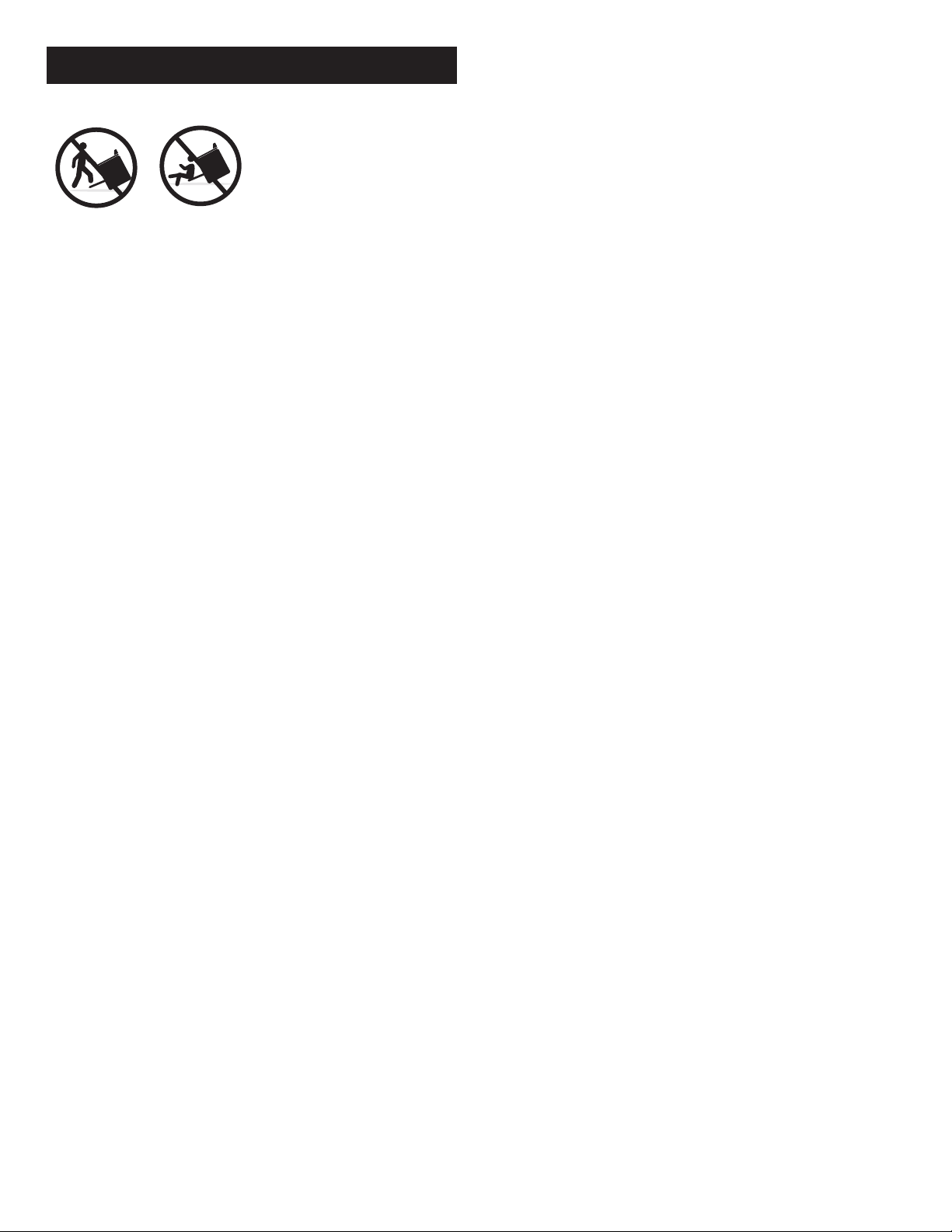
Safety
Your range, like many other household items, is heavy and
can settle into soft floor coverings such as cushion vinyl or
carpeting. When moving the range on this type of flooring
use care.
If your range must stand beside a refrigerator, allow at
least 2” between the two appliances for air circulation. The
heat from the range may affect refrigerator performance.
Make sure that all the packing materials have been removed
and that all controls are in the off position before plugging
in the power cord.
Electrical Connection
Amperage requirements BTU’s NAT BTU’s LP
Model 1947- 40 Amps, 240 Volts 66,000 59,400
1954- 40 Amps,240 Volts — —
1955- 25 Amps, 240 Volts 43,000 38,700
1956- 10 Amps,110 Volts 59,000 53,100
All ranges come with standard 4 wire range cord
attached. This cord must be plugged into a standard
range receptacle provided by your electrician.
Power Cord Installation on Electric Oven
Models
Be sure your appliance is properly installed and grounded
by a qualified electrician in accordance with installation
instructions and local building codes.
5

The new US revised electrical code states that all new
construction must use a FOUR WIRE range power cord.
Existing construction in the USA may use a three wire
range power cord. Note: The difference is a four wire
cord has a separate (green) ground, a three wire cord is
grounded through the (white) neutral.
When ordering, if a 3 wire cord is specified, you must
purchase that cord at a Home Depot or hardware store.
To install a 3 wire cord, remove the lower back panel of
the ranges so the power block is visible.
Unscrew the terminal nuts and insert the range cord wires
through the bushing hole and attach the wires to the terminal
block. Tighten the 3 nuts. The center wire of the range cord
must go to the center position ont he terminal block. That
center wire must be grounded to the chassis if it has not been
done so at the factory.
• Attach the ringed terminal of the green or bare copper wire
to the range body with the green ground screw.
•
Check power with multimeter. You must have 110 volts
between white and black. You must have 110 volts between
white and red. You must have 220 volts between red and black.
If range receptacle is wired wrong, clock transformer will be
severely damaged and will not be covered by manufacturer’s
warranty.
Replace back panel of range. Plug the power cord
in and turn power on.
SAFETY INSTRUCTIONS – GAS
Important Instructions
Do not use range as a heater. Never use the range as a
kitchen heater. Prolonged use of the range without adequate
ventilation can be hazardous. Oven controls and top burners
are not designed for home heating and component failures
that may result from such abuse are definitely not covered by
the warranty.
WARNING: In the State of Massachusetts, the following
installation instructions apply:
• Installations and repairs must be performed by a qualified
or licensed contractor, plumber, or gasfitter qualified by the
State of Massachusetts.
• If using a ball valve, it shall be a T-handle type.
• A flexible gas connector, when used, must not exceed 3 feet
and or be connected in series.
#1 This installation must conform with local codes and
ordinances. In the absense of local codes, installations must
conform with American National Standard, National Fuel
Gas Code ANSI Z223.1–latest edition (**) or CAN/CGA-
B149–latest edition (***) installation codes.
#2 Input ratings shown on the serial/rating plate are for
elevations up to 2,000 feet (609.6 m). For elevations
above 2,000 feet (609.6 m), ratings are reduced at a rate
of 4% for each 1,000 feet (304.8 cm) above sea level.
Mobile Home Installation
The installation of this range must conform to the
Manufactured Home Construction and Safety Standards,
Title 24 CFR. Part 3280 (formerly the Federal Standard
for Mobile Home Construction and Safety, Title 24, HUD,
Part 280); or when such standard is not applicable, the
Standard for Manufactured Homes Installations 1982
(Manufactured Home Sites, Communities and Setups),
ANSI A225.1q/NFPA 501A* or with local codes.
The installation of this range must conform with the
current standards CAN/CSA-Z240–latest edition*** or
with local codes. When this range is installed in a mobile
home, it must be secured to the floor during transit. Any
method of securing the range is adequate as long as it
conforms to the standards listed above.
Note: The metal chassis of the range MUST be earth-
grounded in order for the control panel and burner spark
ignition to work. Check with a qualified electrician if you
are in doubt as to whether the metal chassis of range is
earth-grounded.
Copies of the standards listed may be obtained from:
* National Fire Protection Association
Batterymarch Park
Quincy, Massachusetts 02269
** American Gas Association
1515 Wilson Boulevard
Arlington, Virginia 22209
*** Canadian Standard Association
178 Rexdale Boulevard
Rexdale (Toronto), Ontario M9W 1R3
Floor Covering
Never install a range over inferior kitchen carpeting, vinyl
tile or linoleum. These should be able to withstand at least
175°F without shrinking, warping or discoloring.
Curtains
If your range is near a window, use an appropriate
window treatment. Do not use long curtains which could
blow over the top burners and create a fire hazard.
If You Smell Gas
If this is a new range installation, your installer has not
done a proper job of checking for leaks. Connections can
loosen in transportation. If the range connections are not
perfectly tight, you can have a small leak and therefore a
faint gas smell.
FINDING A GAS LEAK IS USUALLY NOT A
“DO IT YOURSELF” PROCEDURE.
Some leaks can only be found with the controls in the
“on” position exposing the user to serious burns. Never
use a match or flame to locate a leak. Turn off the gas to
the range and call a qualified serviceman.
Flame Size: Top burner flame size should be adjusted so
it does not extend beyond the edge of the cooking utensil.
Excessive flame is hazardous.
Use of High Flame: When using a high flame, never
leave any pans unattended on this heat setting for long
periods. Hot oil is particularly hazardous since it can
become hot enough to ignite.
6

Do not obstruct the flow of combustion and ventilation air
to the range.
Any openings in the wall, behind the range or the floor
under the range must be sealed.
Venting
Never block the vents (air openings of the range). They
provide the air inlet and outlet which is necessary for the
range to operate properly with correct combustion. The
oven vent is located at the rear of the main top.
Type of Gas
Natural and LP Gas (propane). Ranges are factory
assembled for natural gas unless otherwise specified and
cannot be used with LP Gas without some adjustments.
Be sure your range is correctly adjusted by a qualified
serviceman or installer for the type of gas on which it is to
be used. (See Conversion, page 12 -15).
NOTE: In this manual, propane is referred to as LP
(liquid petroleum).
Gas hook up locations - Models 1947 and 1955: The
1/2” steel gas elbow exits the stove on the right side, 33”
off the floor. Model 1956: the connection is located in
the center, 2” off the floor.
INSTALLING YOUR RANGE
WARNING - RANGE TIPPING HAZARD
*
All ranges can tip and injury can result. To prevent
accidental tipping of the range, attach it to the floor,
wall or cabinet by installing the Anti-Tip Bracket
supplied.
*
A risk of tip-over may exist if the appliance is not
installed in accordance with these instructions.
*
If the range is pulled away from the wall for cleaning,
service or any other reason, ensure that the Anti-Tip
Device is properly reengaged when the range is pushed
back against the wall. In the event of abnormal usage
(such as a person standing, sitting, or leaning on an open
door), failure to take this precaution can result in tipping
of the range. Personal injury might result from spilled
hot liquids or from the range itself.
WARNING - ELECTRICAL SHOCK
HAZARD
*
Use extreme caution when drilling holes into the wall or
floor. There may be concealed electrical wires located
behind the wall or under the floor.
*
Identify the electrical circuits that could be affected by
the installation of the Anti-Tip Bracket, then turn off the
power to these circuits.
* Failure to follow these instructions may result in
electrical shock or personal injuries.
WARNING:
• All Ranges can tip.
• Injury to Persons could
result.
• Install Anti-Tip Device
packaged with Range.
• Verify that the Anti-Tip
device is engaged.
• See Installation Instruction.
WARNING
A child or adult can tip the range and be killed.
Install anti-tip bracket to oor or wall per installation
instructions.
Slide range back so rear range foot is engaged in the slot
of the anti-tip bracket.
Re-engage anti-tip bracket if range is moved.
Do not operate range without anti-tip bracket installed
and engaged.
Failure to follow these instructions can result in death or
serious burns to children and adults.
Tip Over Hazard
ATTENTION - PROPERTY DAMAGE
*
Contact a qualied Installer or Contractor to determine
the proper method for drilling holes through the wall or
oor material (such as ceramic tile, hardwood, etc.)
*
Do not slide the range across an unprotected oor.
*
Failure to follow these instructions may result in
damage to wall or floor coverings. Be sure your
appliance is properly installed and grounded by a
qualified technician in accordance with the installation
instructions and local building codes.
7

Tools Needed for Installation of Anti-Tip
Bracket:
*
Screw Driver, #2 Red Robertson (square)
*
Drill, Electric or Cordless
*
Measuring tape
*
1/8”drill bit (wood or metal wall or floor)
*
3/16”carbide-tipped masonry drill bit (concrete or
concrete block wall or floor)
*
3/16”anchors, drywall or concrete, 4 each (not required
if mounting bracket is being attached to solid wood or
metal)
*
Hammer (if installing anchors)
*
Pencil or other marker
IMPORTANT INSTALLATION
INFORMATION:
The Anti-Tip Bracket works in conjunction with either
rear right or rear left leveler-choose which side best suits
your install method. First step is to ensure the leveler is
raised enough to allow the prongs of the Anti-Tip Bracket
to freely slide around leveler bolt-this should be tested
before you fasten bracket to wall or floor.
To correctly determine mounting position of Anti-Tip
Bracket, measure width of cabinet opening. Assuming
range will be centered in middle of opening, mark middle
of opening and measure 14 5/16” for 30” range or
17 5/16” for 36” range -measurement from middle of
opening to outside edge of Anti-tip bracket. This position
will allow leveler bolt to line up with center of “V” in
bracket. Once position is determined, follow below
instructions.
*
The Anti-Tip Bracket may be attached to a solid wood
cabinet having a minimum wall thickness of ¾”
*
The thickness of the wall or floor may require use of
longer screws, available at your local hardware store.
*
In all cases, at least two (2) of the bracket mounting
screws must be fastened to solid wood or metal.
*
Use appropriate anchors when fastening bracket to any
material other than hardwood or metal.
Prepare holes at fastener locations as
identified below:
*
For walls, wall studs or floors composed of solid wood
or metal, drill 1/8”pilot holes.
*
For walls or floors composed of drywall, sheetrock,
or other soft materials, drill 3/16”holes to a minimum
depth of 1 ¾”, then tap plastic anchors into each of the
holes using a hammer.
*
For walls or floors having ceramic tile covering, drill
3/16”holes through the tile only and then drill 1/8”
pilot holes through material behind the tile.
*
Secure bracket with appropriate screws.
*
After gas/electrical connections have been made,
carefully slide range into opening using floor protection
to avoid damage, ensuring that range leveler is engaged
into Anti-Tip Bracket.
*
If range is moved to a new location, or pulled out
from wall and re-installed, installer must ensure range
is engaged into Anti-Tip Bracket before completing
installation. Failure to follow these instructions may
result in death or serious burns to adults and children.
Power cord installation
The new U.S. revised electrical code states that all new
construction must use a FOUR WIRE range power cord.
Existing construction may use a three wire range power
cord. NOTE: The difference is, a four wire cord has a
separate ground. A three wire cord is grounded through
the neutral.
Installation, adjustment and service of this range must
be performed only by a qualified gas range installer or
electrical serviceman. This is necessary to insure proper
operation of the range and to avoid the possibility of
damage to the range or injury to the users.
WARNING: Be careful when reaching into storage cabinets
above range while it is in operation. One might accidentally
contact a hot burner when using a hand for support or have
one’s clothing come in contact with top burner flame.
8
A
B
C
A - Centerline
B - Centerline of cutout to
outside edge of anti-tip
bracket
C - Back wall to back of range
14 5/16” for 30” range
17 5/16” for 36” range

Location
If possible, the range should be located to avoid the main
“traffic path” through the kitchen or where an open door
might block a passageway or create an awkward working
situation. If possible, it should be so located where cabinet
working space is available on either side. Drafty locations
should be avoided to prevent gas burner outage and poor
air circulation.
Temperatures
To cook, you must have heat. Some parts of the range are
therefore going to get warm or even hot. Consider this in
choosing a range location. Do not leave children alone or
unattended near the range when it is in use. Let burner
grids and other surfaces cool before touching them or
leaving them where children can reach them.
Clearances
This range may be installed with adjacent surfaces
touching the base cabinets and the back flush with the
back wall. Models 1947, 1955 and 1956 gas ranges require
a CGA/AGA approved stainless steel gas flex line or a
flexible copper coil 1/2” in diameter and at least three feet
long so the range can be moved for service.
To eliminate the risk of burns or fire by reaching over
heated surface burners, cabinet storage above the range
should be avoided. If overhead storage is unavoidable,
clearances between the cooking surface and unprotected
wood or metal overhead cabinets must be no less than
32”. The clearances on electric models between the
cooktop and unprotected overhead cupboards is 30”. This
distance may be reduced to 24” when the bottom wood
or metal cabinets are protected by not less than 1/4” thick
flame retarding millboard covered with not less than No.
28MSG sheet steel, 0.015” thick stainless steel, 0.024”
thick aluminum or 0.020” thick copper.
NOTE: Clearances specified to combustible construction
(walls and materials) are based on a temperature rise
of wood resulting from appliance operation. These
clearances are suitable for walls of studding, lath and
plaster or other types of combustible material which have
a density of 20 lbs. per cu. ft. or more. No evaluation of
clearances has been made for low density cellulose, fibre
board and similar materials which have a density of less
than 20 lbs. per cu. ft., nor to plastic tiles or sheeting.
The maximum depth of upper cabinets installed above the
range is 13”.
See the Minimum Clearances Chart for electric and gas
models below.
Minimum Clearances to Combustibles
A B C D E F
All Electric Model 1954 0” 0” 30” 0” 0” 13” max.
Dual Fuel Models 1947 & 1955 3”
min.
ht. 18”
3”
min.
ht. 18”
32” 0” 0” 13” max.
All Gas Model 1956 3”
min.
ht. 18”
3”
min.
ht. 18”
32” 0” 0” 13” max.
1 = End of section of overhead cabinet
2 = Overhead center cabinet
3 = End wall or divider
Hood should be installed 28” to 30” from the bottom of
hood to the range cook top.
See Full Installation information
in Exhaust Hood Manual.
It is the responsibility of the installer to comply with the
installation clearances specified in this manual.
Cabinet Openings
Models 1954, 1955 and 1956 will fit into a 30 1/4” cabinet
opening.
Model 1947 will fit into a 36 1/4” cabinet opening.
Leveling Your Range
Place rack in oven. Place level on rack, first side to side,
then front to back.
9

If the range is not level, adjust leveling legs up or down with
pliers or your fingers until range is level.
NOTE: Oven must be level for satisfactory baking performance.
Electrical and Gas Connection Locations
ELECTRIC COOKTOP
Surface Elements
Controls
Control knobs must be pushed
in before turning them to
a setting. They can be set
anywhere between MAX and
MIN.
The controls for the surface
elements provide infinite heat
settings. The numbers on the dial serve as a reference. The
control can be turned to any setting to provide the exact
heat required.
NOTE: The “Push to Turn Safety Control Knobs” on
the range are designed for child safety and to prevent
accidental operation.
Before using your glass cooktop for the first time: turn
the elements on MAX without a pan for 5 to 8 minutes
or until smoking stops. This smoking is normal and
non toxic.
High Speed Radiant - Electric Top Burners
Consists of a set of special RADIANT HEATER coils
embedded in thermal insulation. The element is designed
for fast heat response. You can see it light up almost
immediately.
Each element is fitted with a thermal limiter to ensure
the ceramic glass does not exceed the maximum SAFE
operating temperature. You may notice the element going
on and off a number of times during use. This is a normal
occurrence.
To maximize the efficiency of this type of element we
suggest you use it similarly to your previous burner. Turn to
maximum until the desired temperature is reached, then turn
it down to the setting that best maintains the desired heat.
• H or 9 – To start foods cooking and to bring foods
to a boil.
• 8-7 – To hold a rapid boil.
• 6-5 – To fry foods.
• 4 – To cook large amounts of vegetables
• 3-2 – To keep food cooking after starting it
on a lower setting.
• L – To keep foods warm until ready to serve.
Controls
The radiant heating elements are controlled by a commonly
used Infinite Heat Switch that works on the principle of
percent on, percent off. For example, when the switch is
turned to the medium setting, the element will be on only
50% of the time. Because of the fast heat-up with these types
of elements, you will notice the units switching on and off.
10
Gas line connection is
33" off of the floor and
3.5" in from the right
hand side of the range.
Dual Fuel Range 1947, 1955
Electrical Cord is 12"
up from the floor.
1.5"
1954 All Electric and
1947, 1955 Dual Fuel Ranges
have 220V 4 prong cord.
Plug depth is 1 1/2" and
cord length is 4 feet.
All Gas Range 1956
Electrical Cord is 12"
up from the floor.
Regulator is centered and
approximately 2" in under
the range.
1"
1956 All Gas Model
110V Plug depth is
1" and does not recess
into the range.
Cord length is 3 feet.

Cookware
The best cooking results and the most economical use of
electricity will be achieved by using smooth, flat-bottom
pans. Pans should be at least the same size or slightly
larger than the cooking area. Ceramic cookware suitable
for stovetop cooking may be used. If pans smaller than the
size of the heating element are used, care should be taken
as the handles may get hot.
Built into each element, is a safety device which protects the
element from overheating. If using pans which are not ideal,
for example concave or convex bottom pans with shiny
bases, or those with ridged or grooved bottoms, the thermal
limiter can cause the element to switch off and on during
cooking, which means that food will take longer to cook.
Very thin, badly dented, and distorted pans with uneven
bottoms should not be used.
Pans with very shiny or reflective bottoms should not be
used.
Never place utensils with a skirt (e.g. a wok) on the
heated area.
Pans should not have rough bottoms. Do not slide pots on
the ceramic glass cooking surface, as this may mark or
scratch the cooktop.
If pans with aluminum bottoms are slid across the cooking
surface, metal marks could result. Such marks are easily
cleaned with any non-abrasive stainless steel cleaner,
provided they are removed immediately and not allowed
to bake onto the surface.
Any guidelines or recommendations given by the
saucepan or cooking utensil manufacturer should be
followed.
SELECTION & USE OF POTS & PANS
Flat Bottoms
Thick, flat bottoms absorb and distribute the heat from
the element more evenly. Thin, uneven bottoms waste
energy and create hot spots that may burn the food onto
cookware.
Glass cooktops require heavy gauge flat bottom pans for
best cooking results.
Check flatness with a ruler or straight edge. See figure 7.
Figure 7
Pot Diameter
Select element to match pan diameter. The pot should
be slightly larger than the element to obtain best energy
usage, and avoid spillovers flowing directly onto element.
Do not use pans extending more than one inch beyond
element, except while canning. See figure 8.
Figure 8
Small diameter pans waste energy and spillage can flow
onto element. This increases chance of fire and burns.
Use non-stick coated cookware, for easier clean up.
Glass or pyroceram pans should be used only as the
manufacturer describes.
Pressure cookers, deep fat fryers, canners, etc. must be of
the correct size and have flat bottoms to work properly.
Energy Tips
Use cookware with tight-fitting lids, and flat bottoms
which completely cover the heated portion of the element.
Watch foods when bringing them to cooking temperatures
at high heat. When food reaches cooking temperature,
reduce heat to lowest setting that will keep it cooking.
Use residual heat with surface cooking. For example,
when cooking eggs in the shell, bring water to a boil,
then turn element off, and allow heat in water to complete
cooking.
When boiling water for tea or coffee, heat only the
amount needed. Do not use a wire trivet or any other kind
of heat retarding pad between the pan and the element.
Things Not To Do On A Ceramic Cooktop
• Do not leave pots unattended or elements ON for
extended periods of time. If an element is mistakenly
left on for an extended period of time the built in thermal
limiter will ensure that the heat build-up is insufficient
to cause any adverse effects.
• Do not cook directly on the ceramic cooktop. The
surface of the cooktop can be damaged, and will be more
difficult to clean.
• Do not use wire trivets mats or aluminum foil. They
offer no cooking advantages and can damage the
ceramic glass surface. Never place plastic or any other
material which might melt on any part of the cooktop.
• Do not use the cooktop as a chopping board or cutting
surface. This type of use can scratch the surface.
• Do not leave heavy spills during cooking. Turn heat
off and allow surface to cool down. Remove the spills
11

with a clean, damp cloth (no detergent), taking care to
avoid burning fingers. If there is detergent in the cloth,
you may leave a layer of soil-laden film on the cooktop
surface, which can result in discolouration next time the
element is switched “on”. If a detergent film builds up,
use a ceramic glass cleaner-conditioner.
Care and Cleaning
To keep the exterior chrome trim in spotless condition,
wipe with a warm soapy cloth. Do not clean hot chrome
surface with a soapy cloth, use automotive chrome
cleaner on cool surface.
See page 28 for complete cleaning guide.
Caution - Product Damage Hazard
Before using any cleaners, ensure that it is suitable for
application on chrome trim.
Make sure that the glass ceramic surface has cooled down
before applying any cleaning materials.
1. Saving on Cleaning Time
• Make sure the bottom of pots and pans and cooking area
are clean and dry.
Select correct heat settings and use saucepans large
enough to accommodate food and liquid to eliminate
boilovers and splattering.
• Wipe up food spills and splatters from adjacent heating
areas before cooking.
• Do not drag or slide pots along the surface.
2. Daily Care
• Use a ceramic glass cleaner-conditioner, available
at supermarkets and major department stores. As the
cleaner-conditioner cleans, it leaves a protective coating
of silicone on the smooth surface, which helps prevent
scratches and abrasions in which food particles can
collect. It also helps prevent the build-up of mineral
deposits, and will make future cleaning easier.
• When cool, apply a dab of cleaner-conditioner in the
center of each heated area to be cleaned.
• For normal cleaning start with about 1 ml (1/8 tsp) of
cleaner-conditioner, and apply more if needed.
• Clean unit with a damp clean paper towel. To remove
more stubborn spots, use a slightly dampened non-
impregnated plastic or nylon pad specially made for
non-stick utensils.
• Wipe off this application with another clean, damp paper
towel, and wipe dry.
• Use liquid cleansers to remove any discoloration,
especially in hard water areas. A non-impregnated
plastic or nylon pad specially made for non-stick utensils
may also be used with these cleaners. Do not apply
excessive pressure while rubbing. This could cause
scratches over time.
• Apply cleaner-conditioner and polish with paper towel
or a soft dry cloth.
• Any smearing or hazing on the surface may be removed
with a lightly dampened paper towel, and polished with
a soft dry cloth.
• Do not use a sponge or a dishcloth. They may leave
a film of soil-laden detergent on the heating area
which may turn brown and resemble a discolouration
the next time the area is heated. If that should
happen, cleaner-conditioner will remove it.
Warning
Personal Injury Hazard
• NOTE: If a wet paper towel is used to remove spillovers
from warm cooking area, be careful to avoid steam
burns.
• Never mix different household cleaning products.
Chemical mixtures may interact, with objectionable or
even hazardous results.
Do Use
Ceramic glass cleaner-conditioner should be used
regularly to clean and protect glass-smooth top cooking
surface. If you run out, you may temporarily use baking
soda as a cleaning powder.
Do Not Use
1. Household detergents and bleaches.
2. Impregnated plastic or nylon pads.
3. Soap pads; these will scratch and mark.
4. Household abrasive powders except where specified;
these may scratch depending on the pressure applied in
use.
5. Chemical oven cleaners, e.g. aerosols and oven pads.
These are caustic cleaners, and may etch the surface.
6. Rust stain or bath and sink stain removers, as these will
mark and etch the surface.
7. Metal scrubbers.
How To Deal With Burned-On Spots (Model 1954)
1. Make sure area to be cleaned is warm to the touch.
2. The careful use of a stainless steel razor blade held at
approximately 30 degrees to the surface can be used to
remove stubborn burned-on spots from the surface.
3. Use cleaner-conditioner, and finally wipe the cooktop
clean with a paper towel or damp cloth.
If after the use of recommended materials there are some
persistent stains or marks on the cooktop, the unit should
be cleaned using a liquid cleanser. This will remove any
accumulated residue of cleaner-conditioner, and if applied
with a non-impregnated plastic or nylon pad for non-stick
pans, for at least three to four minutes, it will also take
off the film caused by salts and minerals before it has an
opportunity to discolor or develop into a problem. Finish
off with a touch of cleaner-conditioner, polish to a high
lustre.
12

Any smearing or streaking on the surface may be removed
with lightly dampened paper towel and polished with a
soft dry cloth.
Metal Marks
Certain metal pots, especially those with aluminum
bottoms may leave marks on the surface, especially
if the pan is allowed to slide. Use the cleaner-
conditioner before the unit is used again to
prevent the mark from baking on the surface.
Caution (Model 1954)
Product Damage Hazard
Ceramic glass cleaner-conditioner should be applied
regularly after use of other cleaners, otherwise over
a period of time the surface of the ceramic glass may
roughen, and cleaning will become progressively more
difficult. Staining may also occur.
Important Notes
1. In the event of the cooktop being scratched, soil will
collect and appear as fine lines. These are not fully
removable, but can be minimized by the daily use
of cleaner-conditioner. These scratches do not affect
cooking performance.
2. Soil from sugar solutions must be removed from the
cooktop before the syrup has set, otherwise it can
permanently bond to the ceramic surface.
CANNING
For best results, use a flat bottom, heavy gauge canner.
Canners with rippled bottoms will not work on electric
burners because the bottom does not make enough contact
with the element.
GAS COOKTOP
Gas cooktops are more forgiving than electric cooktops.
Most cookware will work, although tight fitting lids are
recommended for efficient cooking on both. Always
adjust the burner controls so that flames do not extend
past the edges of pots or pans.
Top Burners (Models 1947, 1955, 1956)
Your gas range is equipped with “state of the art” “Sealed
Gas Burners” and an “Auto-Reignition System”. The
sealed gas burners spread the heat evenly across the
bottom of the cooking utensil and provide infinite heat
control. The auto-reignition system senses when a burner
flame has gone out and will automatically reignite that
burner. There are no standing pilots to light or adjust.
See this page for cleaning and maintenance of top burners.
Operating Range During a Power Failure
To light a top burner during a power failure, hold a lit
match to the desired burner head. Turn the corresponding
control knob to any numbered position. After burner
lights, adjust flame to desired setting.
The gas oven requires electricity to operate.
Removal of Burner Knobs
Apply a piece of duct tape to the surface of the knob for
better grip. Pull off by hand or with a pair of pliers.
Manual Burner Adjustment On Low
The burners have been pre-adjusted at the factory for
best performance. You may manually adjust the low
settings up or down by removing the control knob while
the burner is lit and in the low position. While holding
the valve stem so it doesn’t turn, insert a small flat blade
screwdriver into the stem and turn the small brass screw
slightly in either direction until desired flame height is
obtained. Valve must be adjusted so low flame licks
around burner cap no less than 1/8”. See figure 11.
1/8"
Figure 11 Figure 12
NOTE: Low adjustment will not effect flame heights at
other settings. If a top burner flame has been adjusted too
low, the electronic ignitor may start to spark while burner
is on. Readjust flame until ignitor stops sparking.
13

Flame Appearance
The burners have been pre-adjusted at the factory to a
clean blue flame. On LP gas, a slight orange tip may be
visible. If flame is not as above, your gas serviceman
can check the regulator for proper setting with a water
manometer (U-gauge). The stove pressure should be
within + or - 10% of the pressure setting shown in this
manual.
GAS BURNER CLEANING
• The burner caps should be routinely removed and
cleaned. Always clean burner caps after a spillover.
Keeping the burner caps clean aids in proper ignition and
an even flame. Set burner caps into indents in burner base.
• For proper flow of gas and ignition of the burner, DO
NOT ALLOW SPILLS, FOOD, CLEANING AGENTS
OR ANY OTHER MATERIAL TO ENTER THE GAS
ORIFICE OPENING.
• Gas must flow freely through the small hole in the brass
orifice for the burner to light properly. This area must
be free of any soil and be kept protected from boilovers
or spillovers. ALWAYS keep the burner caps in place
whenever a surface burner is in use.
Occasionally check the burner flames for proper size and
shape as shown. A good flame is blue in color. If flames
lift off ports they are yellow and usually noisy. You may
need to clean the burners. See figure 12.
If Ignitors Continue to Click:
If your ignitors continue to click after lighting, the
probable cause is dirt or moisture around the burner,
or between the burner and ignitor. Clean these areas
thoroughly with household cleaner or soap and water.
Dry thoroughly or sparking may still occur. (You may
have to use a hair dryer to completely dry the area.) If
the condition persists, but on low setting only, you may
need to increase the burner flame (see “Manual Burner
Adjustment” – this page). If the condition persists, check
for damaged ignitors. Very rarely, the spark module may
need to be replaced. Ignitors and spark modules, with
installation instructions, can be ordered from Elmira Stove
Works, and must be serviced from under the cook top.
To Clean Burners:
1. Lift the burner cap straight up from the burner base.
2. Clean burner cap with warm, soapy water and a sponge.
You can also clean with a nonabrasive scrubbing pad or
cleanser. Do not clean burner cap in dishwasher.
3. If the gas orifice opening has become soiled or clogged,
use a cotton swab or a soft cloth to clean the area.
4. If ports are clogged, clean with a straight pin. Do not
enlarge or distort port. Do not leave anything stuck
in the ports.
5. After cleaning the orifice opening and ports, replace the
burner cap. Make sure cap is set straight on burner and
that the tabs on cap fit into the grooves of burner base.
6. Check the burner for proper lighting after cleaning.
7. Replace the burner cap, making sure the alignment pins
on the cap are properly aligned with the burner base.
8. Turn on the burner. If the burner does not light, check
cap alignment. If the burner still does not light, do not
service the sealed burner yourself. Contact a trained
repair specialist.
NOTE: If a gas burner burns with an uneven orange
flame, reposition the burner cap so it sits flat on the
burner housing. If burner lights slowly, have your gas
service person check the gas pressure to the appliance.
If a top burner flame has been adjusted too low, the
electronic ignitor may start to spark. Readjust flame on
low until ignitor stops sparking.
When cleaning around the surface burner, use care. If
cleaning cloth should catch the ignitor, it could damage it,
preventing ignition.
If surface burner does not light, check if ignitor is broken,
soiled or wet. If clogged, clean the small port beneath the
ignitor using a straight pin.
Wipe acid or sugar spills as soon as the cooktop has cooled
as these spills can discolor the surface.
See Cleaning Guide – Page 28.
OVEN VENTING - MODEL 1956
The Oven Vent
14

Hot air and moisture
escape from the oven
through a vent in the
center rear of the
cooktop. Do not block
the vent. Poor baking/
roasting and bad
combustion can result.
The oven bottom must
be in place for burner
to bake properly on
model 1956.
GAS SUPPLY SYSTEM
Gas and Electrical Supplies
Before connecting to the supply systems, be sure that
the installation conforms with the local codes or, in the
absence of local codes, with the National Fuel Code,
ANSI Z223.1 latest edition or in Canada, CAN/CGA B149
installation codes. See page 4 for electrical requirements.
Gas Piping to Range
The gas supply piping to the range should be 3/4” pipe
which is then reduced to 1/2” at the regulator. With
“LP” gas, the size of the piping to the range should be
determined by your gas fitter.
When connecting pipe to the die cast regulator fitting, use
two wrenches. Excess pressure or tightening the pipe too
tight can cause the regulator to crack, resulting in a gas
leak or a possible fire or explosion.
Make sure that if flexible connectors are used in
connecting the appliance to the gas supply, they are AGA
and/or CGA approved. Poorly designed connectors can
be a source of gas leaks. Even if AGA/CGA approved
flexible connectors are used, the customer should be
cautioned against kinking or damaging the connection
when moving or cleaning the range. This could cause a
gas leak.
Manual Shutoff
Install a manual shutoff valve in the gas line, in an
accessible location, near the unit. Know where the gas
valve is so you can shut off the gas to the range quickly.
Suitable pipe thread sealant must be used which is
approved for use with “LP”/Natural gas. Be sure to use
this thread sealant on all pipe connections.
Pressure Testing
The appliance, and its individual shutoff valve must be
disconnected from the gas supply piping system during
any pressure testing of that system at test pressures in
excess of 1/2 psi (3.5 kPa).
The appliance must be isolated from the gas supply piping
system by closing its individual manual shutoff valve
during any pressure testing of the gas supply system at
test pressures equal to or less than 1/2 psig (3.5kPa).
The gas supply pressure for checking the regulator
setting shall be at least one inch w.c. above
manufacturer’s specified manifold pressure.
Gas Leak Testing
After the final gas connection has been made, all the
top burner valves should be closed and the gas supply
and manual shutoff turned on. All connections in the
gas supply line and in the range should be tested with
soap suds or electronic sniffer for leaks. If a leak is
present, bubbles will appear. The leak should be stopped
by tightening the joint, or unscrewing completely and
applying additional pipe dope and re-tightened. Any
factory connections which may have been disturbed
should be retested.
A match should never be used when testing for leaks.
All fittings have been tightened and tested at the
factory. If a leak is detected, tighten the fitting. Don’t
use pipe dope on factory fittings.
FUEL CONVERSION OF RANGE TOP
Warning – Fire Hazard
• Locate gas supply shut off valve to the appliance.
• Shut off gas supply before converting fuels.
• Make all conversions before turning gas supply back on.
Failure to follow these instructions could result in fire,
explosion or other personal injury.
Models 1947, 1955 & 1956
All of our ranges are factory set to burn natural gas unless
“LP” is specified. If you are converting from Natural Gas
15
GAS-SUPPLY PRESSURE REQUIREMENTS*
Gas Type Minimum Manifold
Pressure
Min. Gas-Supply
Pressure**
Natural Gas
Liquid Propane (LP)
5-in. Water Column
10-in. Water Column
6-in. Water Column
11-in. Water Column
*Gas-supply pressure for testing the regulator setting shall be at least 1 in. water
column (249 Pa) above the specified manifold pressure; **Max. gas-supply pressure
for all models: 1/2 psi.

to “LP”, or from “LP” to Natural Gas , please following
the instructions below:
Order the required conversion kit from the factory.
SAVE THE ORFICES REMOVED FROM THE
APPLIANCE FOR FUTURE USE.
Burner Large Medium Small
Nat. Gas #50 (1.75 mm) #55 (1.32 mm) #57 (1.09 mm)
LP/Propane #64 (.91 mm) #65 (.89 mm) #70 (.71 mm)
Gas orifice spuds are stamped with the number on the
side. Be sure to replace the correct orifices based on the
chart above.
Fuel Conversion of Regulator on Models
1947 and 1955
Disconnect Power to Range
• Open oven door and remove it, see removal instructions
on page 16.
• With a Phillips driver, undo the 2 screws holding the top
down (center of range, below cooktop).
• Pull top forward about 2” then lift front. Raise the
service stay on each side to hold the top up.
• Regulator (A) is located on the back right area under the
cooktop.
Unscrew and remove the regulator cap (B) from the front
center of the regulator by turning counter clockwise.
• Do not remove spring behind regulator cap.
• Pull pin (C) out of regulator cap.
• For Natural Gas, pin should be snapped back into
regulator cap as in Diagram 2.
• For Liquid Propane (LP) Gas, pin should be snapped
back into regulator cap as in Diagram 3.• Reinstall
regulator cap (B) into regulator, making sure nut does not
cross-thread. Do not over-tighten.
• Lower and re-attach cooktop with 2 screws
A
C
B
Diagram 3Diagram 2
Replacing rangetop orifices
Tools required to replace orifices.
Small adjustable wrench.
1. Remove burner caps.
2. With the small adjustable wrench, unscrew the Brass
Venturi and remove.
3. Remove the orifices in each of the top burners by
turning the 7 mm nut driver counter clockwise. Putting
a piece of folded masking tape inside the nut driver-
sticky side out, will help hold the spud in the driver while
removing and replacing spuds.
4. Replace the removed orifice spud with the correct and
corresponding new orifice spud as per the chart. Orifice
sizes are stamped on the side of orifice spud.
5. Reinstall the Brass Venturi.
6. When installing the burner caps, be sure that the tabs in
the cap fit into the grooves of the burner base.
16

Nat. Gas LP/Propane
Large Burner Takes 1.75 mm (#50) .91 mm (#64)
Medium Burner Takes 1.32 mm (#55) .89 mm (#65)
Small Burner Takes 1.09 mm (#57) .71 mm (#70)
– Fire Hazard
• Locate gas supply shut off valve on the pressure
regulator.
• Shut off gas supply before converting to L.P. gas.
• Make all conversions before turning gas supply valve
back on.
Failure to follow these instructions could result in fire,
explosion or other personal injury.
Fuel Conversion of Regulator on Models
1956 (gas oven)
Disconnect Power to Range
• Remove storage drawer. See page 22
• Locate the regulator at the rear of storage drawer
compartment. This may also be serviced from rear of range.
Remove or Replace Oven Bake Burner
Cover
1. Unscrew the terminal nuts and insert the range cord
wires through the bushing hole and attach the wires to
the terminal block. Tighten the 3 nuts. The center wire
of the range cord must go to the center position on the
terminal block. That center wire must be grounded to
the chassis if it has not been done so at the factory.
2. Align notches on the oven bake burner cover with
shoulder screws in the bottom of the oven.
17
26
6.
Pull electrode out of bracket.
7. Apply masking tape to the end of a 1/4" (6.4 mm) nut driver to
help hold the gas orice spud in the nut driver while changing
it. Insert nut driver into the gas opening, and press down onto
the gas orice spud, then remove by turning the propane gas
orice spud counterclockwise and lifting out. Set propane gas
orice spud aside.
88..Propane gas orifice spuds are marked with a number. Install
the oven bake burner orifice spud.
99..Place Propane gas orifice in plastic parts bag for future use,
and keep with package containing literature.
10. Push down on the clip on the electrode bracket.
11. Replace oven bake burner electrode inside bracket.
12. Reinstall the oven bake burner and oven bake burner screws.
See Step 4 for illustration.
13. Replace oven bafe and oven bafe nuts. The front holes will
be aligned, and a click will sound when bafe is seated.
A
B
A. Grasp electrode here.
B. Bracket
A
A. Propane gas orice spud
A
B
A. Oven bake burner electrode bracket
B. Electrode bracket clip
A
B
A. Oven bake burner electrode
B. Oven bake burner electrode bracket
OVEN CONVERSION MODEL 1956
TO PROPANE
27
Replace Oven Bake Burner Cover
1. Align notches on the oven bake burner cover with shoulder
screws in the bottom of the oven.
2. Lower cover, and slide to left or right to slide shoulder screws
into the narrow ends of the notches, then lock intoplace.
Convert Oven Broil Burner (30" [76.2 cm] and 36"
[91.4 cm] models and the right oven cavity on 48"
[121.9 cm] models)
1. Using a 1/4" (6.4 mm) nut driver, remove broil burner screw.
Set aside with side igniter positioned on the right.
2. Pull the broil burner toward you until it slides out of the hole in
the oven back, and pull the electrode out of the bracket. The
broil burner will hang down in the back of the oven while you
change the orice.
3. Apply masking tape to the end of a 7 mm nut driver to help hold
the gas orifice spud in the nut driver while changing it. Insert
nut driver into the gas opening, and press down onto the gas
orifice spud, then remove by turning the orifice spud
counterclockwise and lifting out. Set natural gas orifice spud
aside.
4. Natural gas orice spuds are stamped with a letter and a
number. Install the Number 148 oven broil burner orice spud.
5. Place Propane gas orice in plastic parts bag for future use,
and keep with package containing literature.
6. Replace the broil burner in the hole in the oven back with the
broil burner assembly inside the broil burner electrode hole as
illustrated.
7. Reinstall the oven broil burner screw. See Step 1 for
illustration. The screw is aligned with the hole when
aclicksounds.
B
AB
A
A. Cover notches (4)
B. Shoulder screws (4)
A
A. Bake burner cover
B
A
C
A. Broil burner screw
B. Broil burner
C. Broil burner orice hole
A
B
A. Grasp electrode here.
B. Bracket
Broil burner hanging
in back of oven
A
B
C
A. Oven back
B. Broil burner orice
C. Broil burner orice hole
ABC
A. Broil burner orice hole
B. Broil burner electrode
C. Broil burner electrode hole
3. Lower cover, and slide to left or right to slide shoulder
screw into the narrow ends of the notches, then lock
into place.
26
6. Pull electrode out of bracket.
7. Apply masking tape to the end of a 1/4" (6.4 mm) nut driver to
help hold the gas orice spud in the nut driver while changing
it. Insert nut driver into the gas opening, and press down onto
the gas orice spud, then remove by turning the propane gas
orice spud counterclockwise and lifting out. Set propane gas
orice spud aside.
88..Propane gas orifice spuds are marked with a number. Install
the oven bake burner orifice spud.
99..Place Propane gas orifice in plastic parts bag for future use,
and keep with package containing literature.
10. Push down on the clip on the electrode bracket.
11. Replace oven bake burner electrode inside bracket.
12. Reinstall the oven bake burner and oven bake burner screws.
See Step 4 for illustration.
13. Replace oven bafe and oven bafe nuts. The front holes will
be aligned, and a click will sound when bafe is seated.
A
B
A. Grasp electrode here.
B. Bracket
A
A. Propane gas orice spud
A
B
A. Oven bake burner electrode bracket
B. Electrode bracket clip
A
B
A. Oven bake burner electrode
B. Oven bake burner electrode bracket
1. Remove oven bake burner cover. See Page 19.
2. Remove bracket that fastens the bake burner to oven.
3. Slide bake burner out so the gas orifice may be seen.
4. Apply masking tape to the end of a 7 mm nut driver to
help hold the gas orifice spud in the nut driver while
changing it. Insert nut driver into the gas opening, and
press down onto the gas orifice spud counterclockwise
and lifting out. Set natural gas orifice spud aside.
5. Install propane bake burner orifice with 7 mm nut driver
and tighten.

18
27
Replace Oven Bake Burner Cover
1. Align notches on the oven bake burner cover with shoulder
screws in the bottom of the oven.
2. Lower cover, and slide to left or right to slide shoulder screws
into the narrow ends of the notches, then lock intoplace.
Convert Oven Broil Burner (30" [76.2 cm] and 36"
[91.4 cm] models and the right oven cavity on 48"
[121.9 cm] models)
1. Using a 1/4" (6.4 mm) nut driver, remove broil burner screw.
Set aside with side igniter positioned on the right.
2. Pull the broil burner toward you until it slides out of the hole in
the oven back, and pull the electrode out of the bracket. The
broil burner will hang down in the back of the oven while you
change the orice.
3. Apply masking tape to the end of a 7 mm nut driver to help hold
the gas orifice spud in the nut driver while changing it. Insert
nut driver into the gas opening, and press down onto the gas
orifice spud, then remove by turning the orifice spud
counterclockwise and lifting out. Set natural gas orifice spud
aside.
4. Natural gas orice spuds are stamped with a letter and a
number. Install the Number 148 oven broil burner orice spud.
5. Place Propane gas orice in plastic parts bag for future use,
and keep with package containing literature.
6. Replace the broil burner in the hole in the oven back with the
broil burner assembly inside the broil burner electrode hole as
illustrated.
7. Reinstall the oven broil burner screw. See Step 1 for
illustration. The screw is aligned with the hole when
aclicksounds.
B
AB
A
A. Cover notches (4)
B. Shoulder screws (4)
A
A. Bake burner cover
B
A
C
A. Broil burner screw
B. Broil burner
C. Broil burner orice hole
A
B
A. Grasp electrode here.
B. Bracket
Broil burner hanging
in back of oven
A
B
C
A. Oven back
B. Broil burner orice
C. Broil burner orice hole
ABC
A. Broil burner orice hole
B. Broil burner electrode
C. Broil burner electrode hole
BROIL BURNER CONVERSION
TO PROPANE
26
6. Pull electrode out of bracket.
7. Apply masking tape to the end of a 1/4" (6.4 mm) nut driver to
help hold the gas orice spud in the nut driver while changing
it. Insert nut driver into the gas opening, and press down onto
the gas orice spud, then remove by turning the propane gas
orice spud counterclockwise and lifting out. Set propane gas
orice spud aside.
88..Propane gas orifice spuds are marked with a number. Install
the oven bake burner orifice spud.
99..Place Propane gas orifice in plastic parts bag for future use,
and keep with package containing literature.
10. Push down on the clip on the electrode bracket.
11. Replace oven bake burner electrode inside bracket.
12.
Reinstall the oven bake burner and oven bake burner screws.
See Step 4 for illustration.
13.
Replace oven bafe and oven bafe nuts. The front holes will
be aligned, and a click will sound when bafe is seated.
A
B
A. Grasp electrode here.
B. Bracket
A
A. Propane gas orice spud
A
B
A. Oven bake burner electrode bracket
B. Electrode bracket clip
A
B
A. Oven bake burner electrode
B. Oven bake burner electrode bracket
26
6. Pull electrode out of bracket.
7. Apply masking tape to the end of a 1/4" (6.4 mm) nut driver to
help hold the gas orice spud in the nut driver while changing
it. Insert nut driver into the gas opening, and press down onto
the gas orice spud, then remove by turning the propane gas
orice spud counterclockwise and lifting out. Set propane gas
orice spud aside.
88..Propane gas orifice spuds are marked with a number. Install
the oven bake burner orifice spud.
99..Place Propane gas orifice in plastic parts bag for future use,
and keep with package containing literature.
10.
Push down on the clip on the electrode bracket.
11.
Replace oven bake burner electrode inside bracket.
12. Reinstall the oven bake burner and oven bake burner screws.
See Step 4 for illustration.
13. Replace oven bafe and oven bafe nuts. The front holes will
be aligned, and a click will sound when bafe is seated.
A
B
A. Grasp electrode here.
B. Bracket
A
A. Propane gas orice spud
A
B
A. Oven bake burner electrode bracket
B. Electrode bracket clip
A
B
A. Oven bake burner electrode
B. Oven bake burner electrode bracket
26
6. Pull electrode out of bracket.
7. Apply masking tape to the end of a 1/4" (6.4 mm) nut driver to
help hold the gas orice spud in the nut driver while changing
it. Insert nut driver into the gas opening, and press down onto
the gas orice spud, then remove by turning the propane gas
orice spud counterclockwise and lifting out. Set propane gas
orice spud aside.
8
8
.
.
Propane gas orifice spuds are marked with a
number. Install
the oven bake burner orifice spud.
99..Place Propane gas orifice in plastic parts bag for future use,
and keep with package containing literature.
10. Push down on the clip on the electrode bracket.
11. Replace oven bake burner electrode inside bracket.
12. Reinstall the oven bake burner and oven bake burner screws.
See Step 4 for illustration.
13. Replace oven bafe and oven bafe nuts. The front holes will
be aligned, and a click will sound when bafe is seated.
A
B
A. Grasp electrode here.
B. Bracket
A
A. Propane gas orice spud
A
B
A. Oven bake burner electrode bracket
B. Electrode bracket clip
A
B
A. Oven bake burner electrode
B. Oven bake burner electrode bracket
Using a Philips driver, remove broil burner screw.
Set aside with side igniter positioned on the right.

SETTING CLOCK – ALL MODELS
Setting clock initially or after power failure (if control is
flashing)
1. To set time: Touch UP or DOWN button until correct
time is shown.
Resetting time (if control is not flashing)
2. Push SELECT 5 times until CLOCK light is
illuminated. Push UP or DOWN until correct time is
shown.
NOTE: You must act within 3 seconds or the function you
are trying to set will cancel.
SETTING MINUTE TIMER:
1. Touch SELECT once. 00:00 will appear. Within
3 seconds press UP for time in minutes.
BAKE OR BROIL
Turn Selector switch to bake or broil. Set oven thermostat
to desired temperature.
Preheating oven on bake normally takes about 15 minutes,
indicator cycle light will go out when oven has reached
temperature. The Broiler takes about 3 minutes to preheat.
After preheating, broiler may be set to variable tempera-
tures by adjusting the thermostat.
DELAYED BAKE
(Oven turns on and off automatically:
1. Touch SELECT 2 times. Current time will flash. Press
UP until the correct START TIME has been reached.
Wait 3 seconds. Touch SELECT once. COOKTIME
will appear. Press UP until the proper cooktime has
been reached. Set the oven selector to AUTO and
thermostat to the correct temperature.
19
27
Replace Oven Bake Burner Cover
1. Align notches on the oven bake burner cover with shoulder
screws in the bottom of the oven.
2. Lower cover, and slide to left or right to slide shoulder screws
into the narrow ends of the notches, then lock intoplace.
Convert Oven Broil Burner (30" [76.2 cm] and 36"
[91.4 cm] models and the right oven cavity on 48"
[121.9 cm] models)
1. Using a 1/4" (6.4 mm) nut driver, remove broil burner screw.
Set aside with side igniter positioned on the right.
2. Pull the broil burner toward you until it slides out of the hole in
the oven back, and pull the electrode out of the bracket. The
broil burner will hang down in the back of the oven while you
change the orice.
3. Apply masking tape to the end of a 7 mm nut driver to help hold
the gas orifice spud in the nut driver while changing it. Insert
nut driver into the gas opening, and press down onto the gas
orifice spud, then remove by turning the orifice spud
counterclockwise and lifting out. Set natural gas orifice spud
aside.
4. Natural gas orice spuds are stamped with a letter and a
number. Install the Number 148 oven broil burner orice spud.
5. Place Propane gas orice in plastic parts bag for future use,
and keep with package containing literature.
6.
Replace the broil burner in the hole in the oven back with the
broil burner assembly inside the broil burner electrode hole as
illustrated.
7.
Reinstall the oven broil burner screw. See Step 1 for
illustration. The screw is aligned with the hole when
aclicksounds.
B
AB
A
A. Cover notches (4)
B. Shoulder screws (4)
A
A. Bake burner cover
B
A
C
A. Broil burner screw
B. Broil burner
C. Broil burner orice hole
A
B
A. Grasp electrode here.
B. Bracket
Broil burner hanging
in back of oven
A
B
C
A. Oven back
B. Broil burner orice
C. Broil burner orice hole
ABC
A. Broil burner orice hole
B. Broil burner electrode
C. Broil burner electrode hole
27
Replace Oven Bake Burner Cover
1. Align notches on the oven bake burner cover with shoulder
screws in the bottom of the oven.
2. Lower cover, and slide to left or right to slide shoulder screws
into the narrow ends of the notches, then lock intoplace.
Convert Oven Broil Burner (30" [76.2 cm] and 36"
[91.4 cm] models and the right oven cavity on 48"
[121.9 cm] models)
1. Using a 1/4" (6.4 mm) nut driver, remove broil burner screw.
Set aside with side igniter positioned on the right.
2.
Pull the broil burner toward you until it slides out of the hole in
the oven back, and pull the electrode out of the bracket. The
broil burner will hang down in the back of the oven while you
change the orice.
3. Apply masking tape to the end of a 7 mm nut driver to help hold
the gas orifice spud in the nut driver while changing
it. Insert
nut driver into the gas opening, and press down onto
the gas
orifice spud, then remove by turning the orifice spud
counterclockwise and lifting out. Set natural gas
orifice spud
aside.
4. Natural gas orice spuds are stamped with a letter and a
number. Install the Number 148 oven broil burner orice spud.
5. Place Propane gas orice in plastic parts bag for future use,
and keep with package containing literature.
6. Replace the broil burner in the hole in the oven back with the
broil burner assembly inside the broil burner electrode hole as
illustrated.
7. Reinstall the oven broil burner screw. See Step 1 for
illustration. The screw is aligned with the hole when
aclicksounds.
B
AB
A
A. Cover notches (4)
B. Shoulder screws (4)
A
A. Bake burner cover
B
A
C
A. Broil burner screw
B. Broil burner
C. Broil burner orice hole
A
B
A. Grasp electrode here.
B. Bracket
Broil burner hanging
in back of oven
A
B
C
A. Oven back
B. Broil burner orice
C. Broil burner orice hole
ABC
A. Broil burner orice hole
B. Broil burner electrode
C. Broil burner electrode hole
27
Replace Oven Bake Burner Cover
1. Align notches on the oven bake burner cover with shoulder
screws in the bottom of the oven.
2. Lower cover, and slide to left or right to slide shoulder screws
into the narrow ends of the notches, then lock intoplace.
Convert Oven Broil Burner (30" [76.2 cm] and 36"
[91.4 cm] models and the right oven cavity on 48"
[121.9 cm] models)
1. Using a 1/4" (6.4 mm) nut driver, remove broil burner screw.
Set aside with side igniter positioned on the right.
2. Pull the broil burner toward you until it slides out of the hole in
the oven back, and pull the electrode out of the bracket. The
broil burner will hang down in the back of the oven while you
change the orice.
3. Apply masking tape to the end of a 7 mm nut driver to help hold
the gas orifice spud in the nut driver while changing it. Insert
nut driver into the gas opening, and press down onto the gas
orifice spud, then remove by turning the orifice spud
counterclockwise and lifting out. Set natural gas orifice spud
aside.
4. Natural gas orice spuds are stamped with a letter and a
number. Install the Number 148 oven broil burner orice spud.
5. Place Propane gas orice in plastic parts bag for future use,
and keep with package containing literature.
6. Replace the broil burner in the hole in the oven back with the
broil burner assembly inside the broil burner electrode hole as
illustrated.
7. Reinstall the oven broil burner screw. See Step 1 for
illustration. The screw is aligned with the hole when
aclicksounds.
B
AB
A
A. Cover notches (4)
B. Shoulder screws (4)
A
A. Bake burner cover
B
A
C
A. Broil burner screw
B. Broil burner
C. Broil burner orice hole
A
B
A. Grasp electrode here.
B. Bracket
Broil burner hanging
in back of oven
A
B
C
A. Oven back
B. Broil burner orice
C. Broil burner orice hole
ABC
A. Broil burner orice hole
B. Broil burner electrode
C. Broil burner electrode hole

TIMED BAKE
(Oven turns off automatically):
1. Touch SELECT 3 times. COOKTIME will appear.
Press UP until the proper cooktime has been reached.
Set the oven selector to AUTO and the thermostat to
the correct temperature.
NOTE: On delayed bake and time bake allow an extra
12 minutes for oven to preheat.
OVEN LIGHT
Press LIGHT. Oven lights will turn on or off.
vs.
CLOCK vs. DIGITAL DISPLAY
If Clock does not agree with Digital Display
1. Press SELECT 5 times. Clock indicator will illuminate.
2. Press UP and DOWN arrows at the same time.
3. Adjust analog hands UP or DOWN to correct time.
4. 12:00 will appear on the display after 3 seconds.
5. Adjust digital time UP or DOWN to match the clock
hands. (start within 3 seconds)
SELF CLEAN
1. Touch SELECT 4 times. CLEAN will appear and 3:00
will be displayed on clock. Although we recommend
3:00 for most oven cleaning, by selecting UP or
DOWN you can change the length of the clean cycle.
Set the oven selector and thermostat to CLEAN.
Within 10 seconds the door will lock and the oven
will start to clean. If you want to cancel oven cleaning
press cancel. If the oven has reached 575°F the oven
door can only be opened after a 30 minute cool down
as shown on the clock. It is a good idea to remove
oven racks before cleaning oven as they will become
discolored.
IMPORTANT
DO NOT TURN SELECTOR AND
THERMOSTAT OFF UNTIL SELF CLEANING
AND COOL DOWN HAVE FINISHED OR
OVEN DOOR WILL NOT OPEN.
Before You Start Self Cleaning
• Hand-clean the areas shown. They do not get hot enough
during the cleaning cycle for soil to burn away, and could
get baked on during cleaning. use hot water and detergent
or a soapy steel-wool pad for cleaning. Oven cleaners
may be used in oven but must be completely removed
before self-cleaning cycle begins.
NOTE: Do not clean, move or bend the gasket. Poor
cleaning, baking and roasting may result.
• Wipe out any loose soil or grease. This will help reduce
smoke during the cleaning cycle.
• Remove the broiler pan grid and anything else being
stored in the oven.
NOTE: If oven racks are cleaned in the self-cleaning
cycle, they will become discoloured and more difficult to
slide.
If you clean racks in the self-cleaning cycle, place them on
the 2nd, 3rd and 4th rack guides.
For Best Cleaning Results
• Clean the oven before it gets heavily soiled. Cleaning a
very soiled oven takes longer and results in more smoke
than usual.
• After the oven is cool, wipe up any residue or ash with
a damp cloth or sponge. If any spots remain, clean with a
mild abrasive cleaners or mildly abrasive pad.
• If the self-cleaning cycle does not get the oven as
clean as you expected, the cycle may not have been
set long enough or you may not have prepared the oven
properly. Set the self-cleaning cycle longer the next time
and hand-clean areas noted above.
By turning exhaust fan on while self-cleaning most
smoke and odor in kitchen will be eliminated.
20
This manual suits for next models
3
Table of contents
Other Elmira Stove Works Range manuals

Elmira Stove Works
Elmira Stove Works 1954 User manual

Elmira Stove Works
Elmira Stove Works 1850 User manual

Elmira Stove Works
Elmira Stove Works 1850 User manual

Elmira Stove Works
Elmira Stove Works 1954 User manual

Elmira Stove Works
Elmira Stove Works 1954 User manual

Elmira Stove Works
Elmira Stove Works 1954 Configuration guide

Elmira Stove Works
Elmira Stove Works 1850 User manual

Elmira Stove Works
Elmira Stove Works 1850 User manual

Elmira Stove Works
Elmira Stove Works 1855 User manual

Elmira Stove Works
Elmira Stove Works 1955 User manual