Elmos E520.30 User manual

Elmos Semiconductor AG Application Note QM-No.: 25DS0129E.00
E520.30 Programmable Smoke Detector Controller AN 0129
Mar 25, 2015
1/8
1 What you get:
1. Smoke Detector
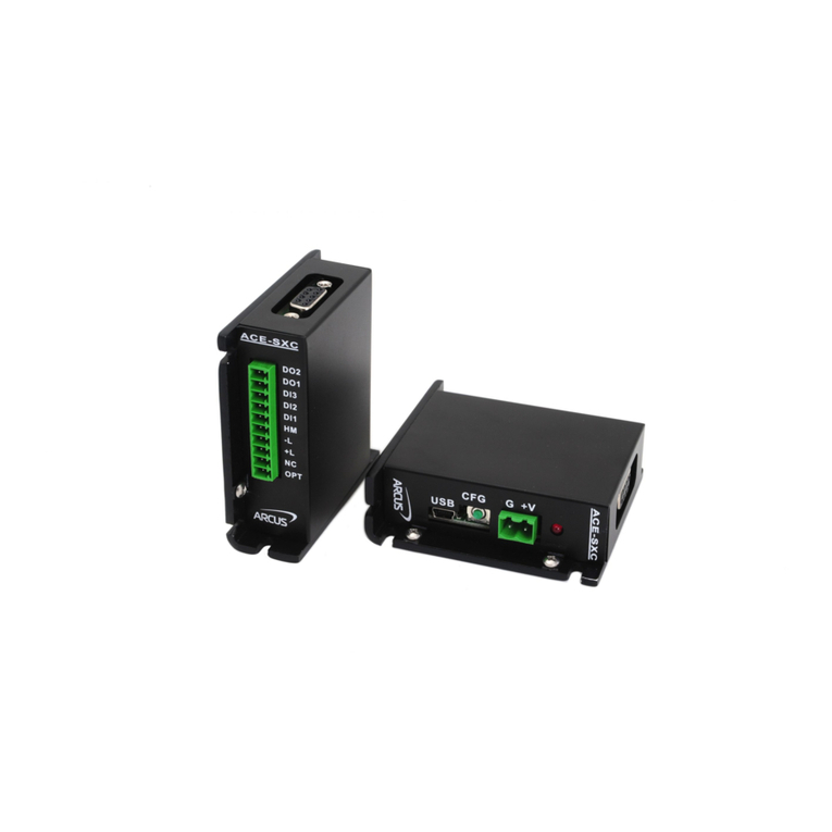
2. E520.30 Interface with cable for connecting smoke detector
3. CD with software and driver
1. PC with Windows operating system and USB interface
1. Connect cable from smoke detector to E520.30 Interface
2. Connect USB cable to PC
3. If necessary, install FTDI driver from driver folder on CD, installation guide in doc folder
4. Start smoke.exe in demo folder on CD
The E520.30 PC driven demonstrator kit is for demonstration purpose of the smoke-detector device functionality. It supports
communication between PC and smoke detector based on E520.30 using the E520.30 Interface (3 level interface). The E520.30
device inside the smoke detector has a special firmware to communicate with the PC using the same protocol.
The PC demo software provide smoke detector device control and parameter modification with graphical output.
For demonstration purpose it is necessary to establish a communication between smoke detector and PC using physical se-
quential interface on two wire bus (LN24 and GND).
2 What you need in addition:
3 Start of operation:
Figure 1. Demoboard
4 E520.30 PC driven demonstrator kit:

2/8
Elmos Semiconductor AG Application Note QM-No.: 25DS0129E.00
E520.30 Programmable Smoke Detector Controller AN 0129
Mar 25, 2015
5 PC based Demo Software:
Start the program smoke.exe.
The program connects automatically to the smoke detector via E520.30 interface.
After connecting the software shows the measured supply voltage and the LN24 supply. The LN24 supply can be set in LN24
Properties window.
To see the smoke density values choose in Functions Remote smoke detector and a history windows appears. Move IR and AMP
sliders to values around 5 :
Figure 2. Start screen
Figure 3. Remote Smoke Detector – Smoke

3/8
Elmos Semiconductor AG Application Note QM-No.: 25DS0129E.00
E520.30 Programmable Smoke Detector Controller AN 0129
Mar 25, 2015
The LN24 voltage is measured with the E520.30 interface and can also be displayed.
LN24 properties can be inspected with LN24 Properties option in the Menu Bar Functions. The following values must be set
for correct communication with the firmware (default at delivery), press “save to EEPROM” button to store new values inside
the µC in the E520.30 interface :
Figure 4. Remote Smoke Detector – Smoke and temp
Figure 5. LN24 properties

4/8
Elmos Semiconductor AG Application Note QM-No.: 25DS0129E.00
E520.30 Programmable Smoke Detector Controller AN 0129
Mar 25, 2015
The E520.30 register values can be read by pressing the readAllRegs button. To change a value click in the nVal field and fill in a
new value in the upcoming window. Confirm with OK. Optionally change more register values and press writeAllRegs to trans-
fer new data to the E520.30.
Figure 6. Read register values
Figure 7. Edit register values

5/8
Elmos Semiconductor AG Application Note QM-No.: 25DS0129E.00
E520.30 Programmable Smoke Detector Controller AN 0129
Mar 25, 2015
The E520.30 interface can be used to flash new content into into the E520.30 device.
To flash new software, please do the following :
• remove connect state in the Function pull down menu in main window
• disconnect smoke detector from E520.30 interface
• open the E520.30 interface, plug in the 14pin ribbon cable into CON4 and connect to 8 pin connector at the bottom of the
smoke detector housing – the 8pin to 14pin adapter only fit in one position
• connect again in the Function pull down menu in main window
• choose Flash in the Memories pull down menu in main window, a new Flash window appear, see Figure 8
• press Load button and choose HEX File for E520.30 device, after reading the hex file the Flash window is filled with data,
see Figure 9
• to program new data first erase Flash by pressing Erase button, then press Write button – a progress bar is visible, see Fig-
ure 10.
• press Verify button and a verify ok window appear, see Figure 11.
• optionally change LN24 properties for new firmware, see Figure 5.
• disconnect smoke detector, remove 14pin ribbon cable and connect green 3pin connector to E520.30 interface and con-
nect again.
Figure 8. Flash window start screen

6/8
Elmos Semiconductor AG Application Note QM-No.: 25DS0129E.00
E520.30 Programmable Smoke Detector Controller AN 0129
Mar 25, 2015
Figure 9. Flash window with Hex File
Figure 10. Flash window during programming
Figure 11. Successful flash verify
This kind of programming is only recommended for testing or lab purpose and it is not intended for production use !

7/8
Elmos Semiconductor AG Application Note QM-No.: 25DS0129E.00
E520.30 Programmable Smoke Detector Controller AN 0129
Mar 25, 2015
LN0
R1
100k
R2
100k
D5
D5
TMS
TCK
TDI
TDO
D2
RED LED
LN0
TCK
LED
1
LN0
2
D5
3
RED
4
DIN
5
DSUP
6
VTDRV
7VTSEN 8
TEN9
IO3/TCK 10
IO2/TMS 11
IO1/TDI 12
IO0/TDO 13
LN24 14
IC1 520.30
TEN
CT1
100uF/6.3V
1
1
3
3
7
75
5
88
66
22
44
CON2
MPE156_8
LN0
TCKTMS
TDOTDI
TEN
D5
LN24
1
2
CON1
COAX_CON
LN0
SW1
DTSM31N
LN0
LN24
2 1
IRLED
43
Photodiode
D5
R3
100k
Figure 12. Schematic of smoke chamber

8/8
Elmos Semiconductor AG Application Note QM-No.: 25DS0129E.00
E520.30 Programmable Smoke Detector Controller AN 0129
Mar 25, 2015
Elmos Semiconductor AG – Headquarters
Heinrich-Hertz-Str. 1 | 44227 Dortmund | Germany
Phone +49(0)231-7549-100 | Fax +49(0) 231-7549-159
sales-germany@elmos.com | www.elmos.com
Note Elmos Semiconductor AG (below Elmos) reserves the right to make changes to the product contained in this publication without notice. Elmos assumes no responsibility for the use of any circuits de-
scribed herein, conveys no licence under any patent or other right, and makes no representation that the circuits are free of patent infringement. While the information in this publication has been checked,
no responsibility, however, is assumed for inaccuracies. Elmos does not recommend the use of any of its products in life support applications where the failure or malfunction of the product can reasonably be
expected to cause failure of a life-support system or to significantly affect its safety or effectiveness. Products are not authorized for use in such applications.
Copyright © 2015Elmos Reproduction, in part or whole, without the prior written consent of Elmos, is prohibited.
Elmos Semiconductor AG provide the E520.30 Demonstration Board simply and solely for IC evaluation purposes in laboratory.
The Kit or any part of the Kit must not be used for other purposes or within non laboratory environments. Especially the use or
the integration in production systems, appliances or other installations is prohibited.
The pcb´s are delivered to customer are for the temporary purpose of testing, evaluation and development of the Elmos IC´s only.
Elmos will not assume any liability for additional applications of the pcb.
Elmos Semiconductor AG shall not be liable for any damages arising out of defects resulting from (1) delivered hardware or soft-
ware, (2) non observance of instructions contained in this document, or (3) misuse, abuse, use under abnormal conditions or
alteration by anyone other than Elmos Semiconductor AG. To the extend permitted by law Elmos Semiconductor AG hereby ex-
pressively disclaims and user expressively waives any and all warranties of merchantability and of fitness for a particular purpose,
statutory warranty of non-infringement and any other warranty or product liability that may arise by reason of usage of trade,
custom or course of dealing.
Usage Restrictions
Disclaimer
Table of contents
