7
Embroidring device
1) The machine is fed, when embroidering, by the X feed STM and Y feed STM. An angle of rotation of each STM is transmitted, by means of a gear and belt, to the
embroidery frame as a linear travel amount in X/Y direction. This causes the machine to sew an embroidery pattern.
2) When a large, medium or small embroidery frame is installed on the machine, three frame detection switches are turned ON or OFF, and the machine determinates
the possible range of layout of the patterns that can be sewn in accordance with the size of embroidery frame, i.e., large, medium or small, installed.
In addition, the number of patterns and letters that can be stored in memory is automatically restricted in accordance with the embroidery frame installed.
3) When the embroidering device is used with the machine, the controller is rendered ineffective and the reverse stitching switch is inoperative.
The maximum speed can be changed over in four steps with the slide variable resistor.
4) If the presser foot is in the lowest position after the power to the machine has been turmed ON, the pictograph "raise presser foot" will be given on the display. If the
needle is in the lowest position, the pictgraph "raise needle" will be shown. The S/S SW is rendered ineffective.
5) If you turn the machine by hand after having selected a pattern, the machine will not perform pattern sewing. Once the S/S SW is turned ON, you are allowed to turn
the machine by hand so as to make the machine perform pattern sewing until the machine completes the pattern. After the completion ofthe pattern sewing, it is
impossible to make the machine perform pattern sewing by turning the machine by hand.
6) The sewing speed automatically changes over, during embroidering, in accordance with the travel amount of the embroidery feeding frame. (800, 750, 410 and 245 rpm)
7) To move the needle by a distance as long as 11 mm (jump) during embroidering, the sewing machine is stopped and only the embroidery frame is moved by the
distance.
8) The micro-switch is used for the detection of the origin.
9) A micro-switch is mounted on the ejection lever, and it informs the micro-computer to cut the power supply to the embroidering device STM before the terminals of
the embroidery and the main unit are drawn. This is a protective circuit not to badly affect the electronic components when the terminals are improperly connected
or they are drawn during sewing.
In addition, when the ejection lever is improperly inserted, the embroidering device does not work. So, be careful.
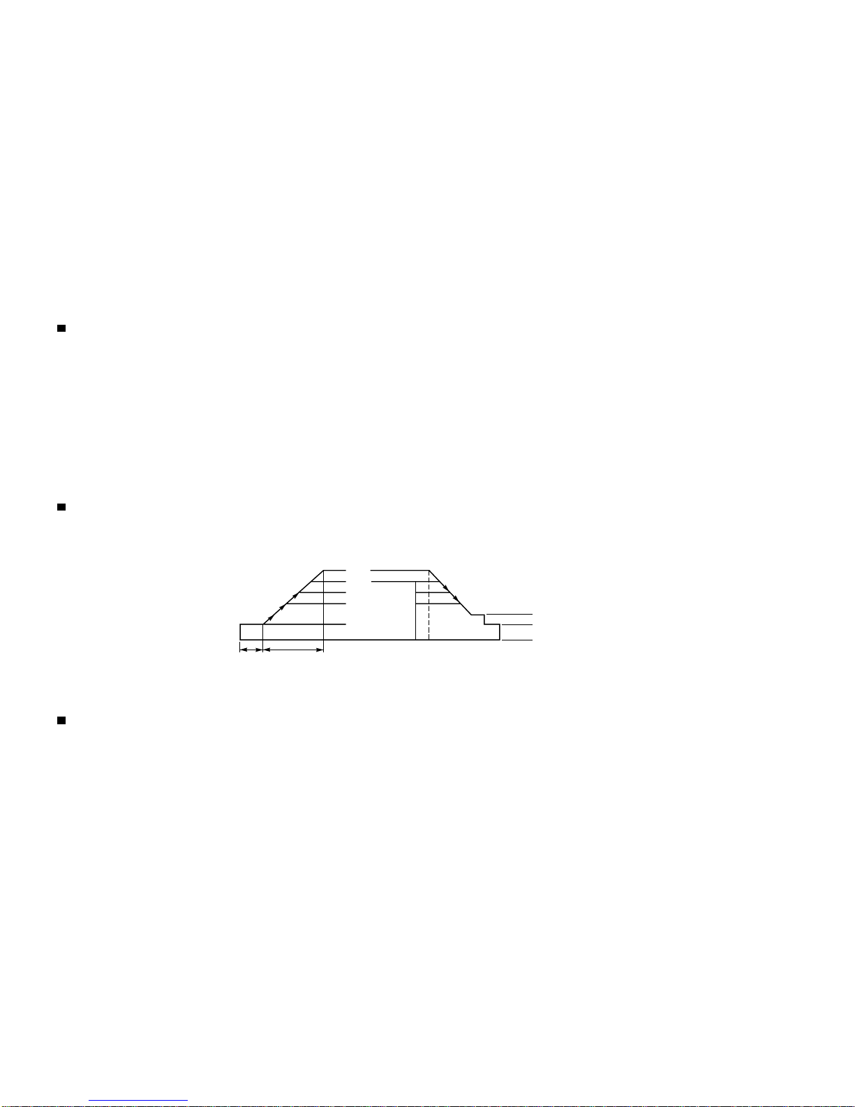
Automatic thread tension control
1) The automatic thread tension control is carried out by the following.
1Pattern data (Zigzag width and feed amount are automatically specified by making a choice of a pattern to be sewn.)
2Material thickness detecting potentiometer
3Thread drawing stepping motor
Based on the data provided by 1and 2, the optimum drawing amount of needle thread for every rotation of the sewing machine is calculated by a microcomputer.
The set amount drawing stepping motor rotates, draws the needle thread put between the drawing roller and the auxiliary roller and controls the amount of thread to
be used for sewing the material.
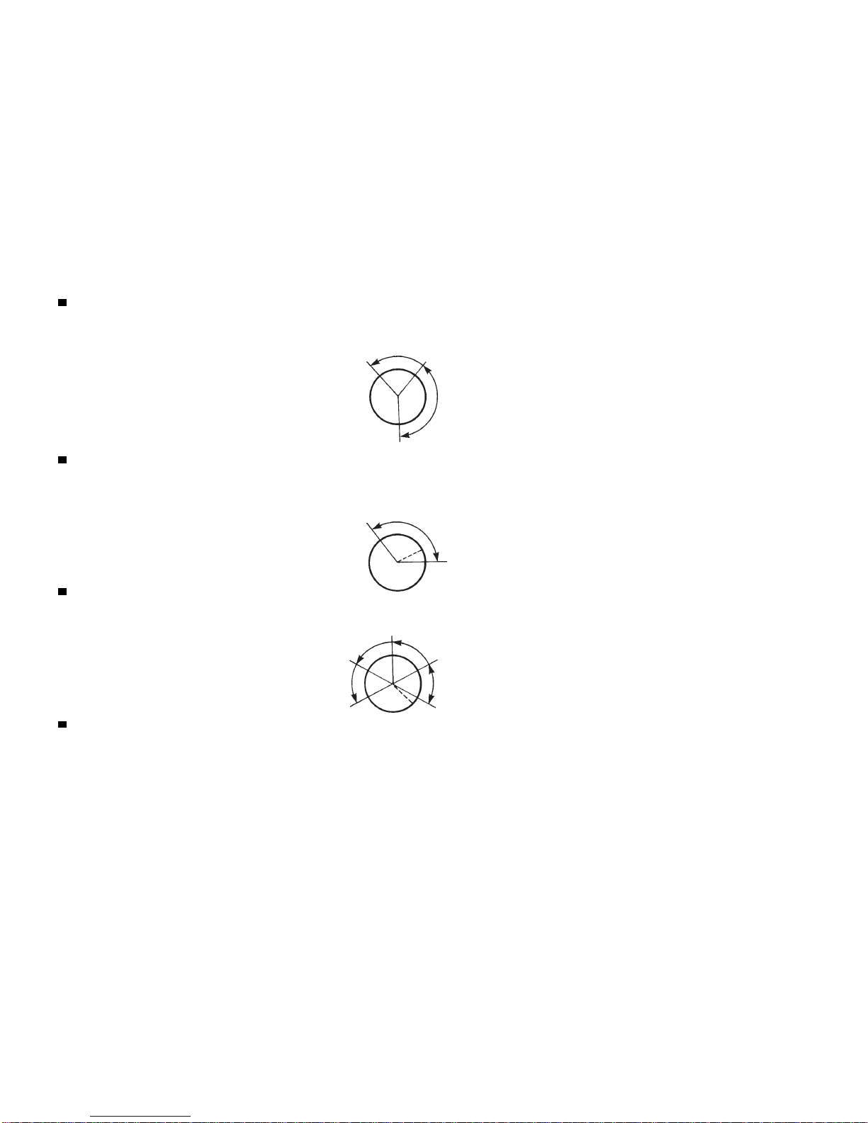
2) Rotate the machine by the amount equivalent to the sewing of several stitches by turning ON the S/S SW or operating the machine by hand, and the slack of thread
will be removed. The automatic thread tension control function works when the thread breakage detection photo-sensor becomes open.
3) For overedging, embroidering, and two color stitching, the thread drawing amount is computed using the respective operation expressions to allow the machine to
adapt to the respective sewing patterns.
4) To correct error in the actual feed amount of the material feed mechanism, sew a straight stitch pattern with the feed amount indication set to 2 mm and measure the
actual feed amount. Then adjust the feed compensating switch in accordance with the difference between the specified amount and the measured feed amount. This
corrects the operation expression used by the microcomputer.