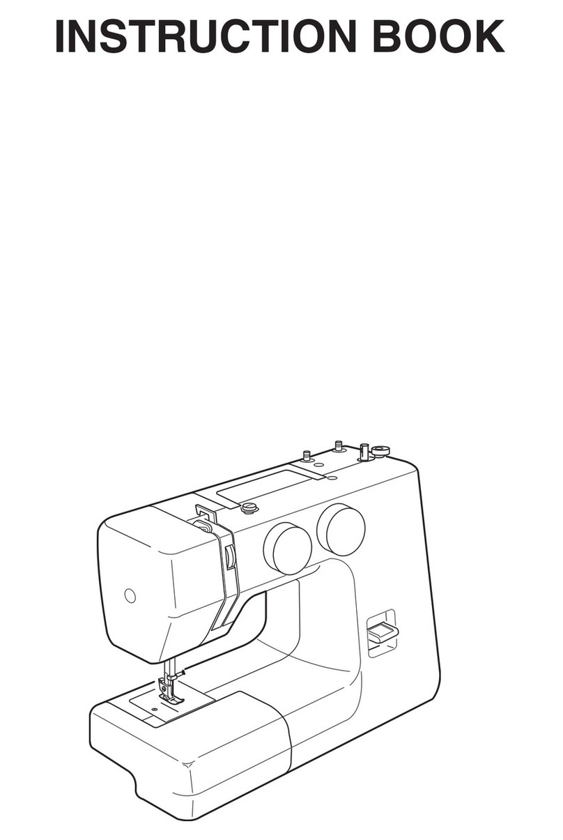
ELNA TX User manual

Instruction
Manual
"This
machine
corresponds
to
the
EEC-prescriptions
76/889"

elna

Your
new
Elna-tx
-
class
57
Everything is then ready
for
your
everyday
sewing
jobs:
The
Instruction
Manual
5
The sewing
foot,
for
the
usual
straight
and zigzag
stitches.
enables
you
to
become
acquainted
with
your
Ena-tx,
to
familiarize
yourself
with its
operation,
manipulation
6
A
number
80
needle
(medium
size).
and
certain
basic
seams.
7
The
thread
tension set
at
the
"Universal"
position,
marked
between
4
I/
and
5
'A
Pages
Description
and
main
parts
2
to
11
There
is
no
longer
any
need
to
adjust
the
pressure
of
the
sewing
foot.
It
is
universal
and
Preparation
of
the
machine
12 to
19
has been
adjusted
at
the
factory
to
cope
with
Adjustments
and
sewing
20
to
41
sheer
as
well
as
thick
fabrics.
Extra
accessories
42
to
45
Maintenance
46
to
47
Service.
Should
you require any
further
information,
please
don't
hesitate
to
ask
your
Elna
dealer.
His
To
remedy minor
disorders
47
to
48
qualified
staff
will
be
glad
to
answer
your questions.
In
accordance
with
the
terms
of
the
guarantee,
he
Is
also
the
only
person authorized
to
attend
to
any
General mechanical adjustments
on
your
Elna.
Please
keep
this
instruction
manual
in
a
safe
place
for
future
reference.
Elna
sewing
machine
All
rights
to
make
any
modifications
reserved.
Record
in
space provided
below
the
Serial
No.
and
Model
No.
of
this
appliance.
The
Serial
No.
Is
located
Rear
of
arm.
Preparation
The
Model
No.
is
located
Rear
of
arm.
You
don't
have
to
remove
your
EIna-tx from
a
case.
Serial
No.
I
Open
it
by
raising
the
clasps
slightly
to
free the
Model
No.
protection
flaps.
Open
the latter
in
the
order
2-4-3
Retain
these
numbers
for
future
reference.
to
form
a
comfortable
sewing
surface.
3

3
1
e~na

Your
ElIna-tx
is
a
convertible
sewing
machine
You
can
use
it
with
the
convenient
sewing
table,
by
To
reclos.
the
flaps:
Turn
the flywheel
by
hand
to
leaving
the
protection
flaps
opened
out,
or
with
the
move
the
thread
take-up
lever
to
its
lowest
free
arm.
position.
You
can
obtain
a
practical
free
arm
by
removing
the
3
protection flaps,
namely:
1-2
Flaps
1
and
2:
open
(or
raise)
the
flaps
to
a
You
then
put the flaps
back
In
place
In
the
reverse
horizontal position
(a),
press
them
towards
the
red
order.
mark
(I)
and
lift
the
other
end
(11).
The
flaps
will
then come
free.
3
Start
by
inserting
flap
3
In
the
slit.
3
Flap
3:
press
the button
(b)
while raising
and
The
red
mark
0*
should
be
on
the
outside.
pulling
the
flap
upwards.
Push
it
right
down,
until
It
clicks
Into
place.
4
You
thus
have
a
free
arm.
It
makes
it
easy
to
sew
2-1
Next,
fit
the
flaps
2
and
1,
holding
them
in
a
the
openings
of
trousers,
the
waistbands
of
skirts,
horizontal position.
Place the
end
marked
In
reda
aprons, patches
on
the
seats
of
trousers, pockets,
(I)
in
the hole
of
the hinge.
Press
the flap
towards
d
n
a
etc.
the
hinge
and
insert
the
other
end
(11)
in
the
hole,
5

66
!a 12
eina
i
,i

Your
EIna-tx
is
easy
to
understand
Here
are
the
other
main
parts:
13
Mains
lead.
1
Stitch
length
dial.
14
Pneumatic
foot
control.
2
Stitch
width
dial.
15
Light
switch
and
motor
switch.
Each
switch
can
be
3
Stitch
selector.
turned
on
or off
Independently.
4
Rotary
hook
cover.
Safety
5
Built-in
sewing
light.
Input
15
w
maximum.
In
accordance
with
the
recommendations
of
6 Universal
upper thread
tension. specialized
safety,
standards
and
electrical control
7
Thread
take-up
lever,
authorities,
the
sewing machine must
be
8
Bobbin
winder.
disconnected
from
the
main
supply
by
removing
the
plug
from
the
socket-outlet
whenever:
9
Retractable
spool
pin.
-the
machine
is left
unattended
10
Flywheel,
with
coupling
knob.
-
the
machine
is
being
serviced
11
Electronic
speed
controller.
-
mechanical
parts
are
changed
12
Specification
plate.
Make
sure
that
the voltage
-
accessories
are
changed.
(volts)
is
the
same
as
that
indicated
on
the
light
-ng
bulbs
in
your
home.
See
also
pages
46-47.
7

56
e
ina
10a
l0b
11l
A
i 7.!i
ii!~~
iiiii!i!! i!!
~
~

The
Accessory
Case
built
into
your
Elne-tx
is
a
true
fitted
case,
where
every
accessory
has its
place.
There is
no
longer
any
separate
box
to
be
mislaid.
it
is
an
integral
part
of
9
Should
you
have
to
change
the
needle
your
Elna-tx.
Hold the
needle
with its
flat
part
against
the
index
1-2Raise
the
clasp
slightly
and
open
the
cover.
In
the
finger
and
push
it
as far as
it
will
go
into
the
1case
you
wils
idhtly
acessoriesnd
eov
he
needle
clamp.
Tighten
the
screw
firmly
(no
need
case
you
will
find
the
accessories
and
removable
for
a
screwdriver).
Use
needles
of
the system
soles
for:
130/
705H
(15
1).
(3
sewing
foot
already
in
place
on
the machine)
10
Should
you
have
to
change
the sole
of
the
foot
4
embroidery
foot
a)
Raise
the
foot.
By
pressing
downwards
on the
sole of
the
foot
with
the
fingers,
it
is
5
zipper
foot
disengaged
and
can
be
removed
easily.
6
blind stitch
foot
b)
Place
the
other
sole under
the
foot
support
attachment.
Lower the
foot
and
press
on the
7
buttonhole
foot
with
slide
support
with
the
fingers
so
that
the
sole
8
darning foot
and plate
engages
by
itself.
2
bobbins
(plus
one
already placed
in
the
rotary
11
If
you
use
a
foot that
is
attached
in
the
hook)
conventional
manner,
the
support fixing
screw
can
Assortment
of
needles
and
a
needle
threader
be
unscrewed,
Remove
the
support
and
attach
the
Small
cleaning
brush
and
oiler
foot
in
its
place.
Tighten
the
fixing
screw
firmly.
Buttonhole
knife
and
seam
ripper
Small
screwdriver
For
the
darning
foot
see
pages
34/35.
9

wi
46bcu1
41
71
eina
elna
10

Operation
7
Electronic
Speed
Controller
1
Foot
Control
With
this
sliding
control,
It
is
possible
to
set,
before
or
during
sewing, the
maximum
speed
The
foot control
Is
not
electric.
It
is
a
pneumatic
desired,
by
sliding
the
knob
upwards
or
foot
control.
It
controls
an
electronic
device
downwards
to
the setting
required
between
the
housed
within the machine,
to
regulate
motor and
"hare"
and
the
"tortoise",
symbolising
the
fast
and
sewing
speeds.
slow
speeds.
2
Connect
the
nozzle
with the
machine.
A
bobbin
winding
position
"I "
shows, too,
the
recommended
speed
for
winding
the bobbin.
3
Plug
in
the
mains
lead.
The
range of
speeds
Is
then
controlled
by
the
4
The
sewing
light
is
situated
in
the
head
of
the
pressure
exerted
on
the
foot
control.
The
greater
machine,
the
pressure,
the
higher
the
speed,
until
the
maximum
speed
set
with
the
electronic
speed
5
It
can
be
switched
on
or off
independently
by
controller
is
reached.
Press
preferably
with
the
pressing
the
light
switch.
Useful
for changing
the
sole of
the
foot
(and
not
with
the
toes).
needle
or
the
bobbin, preparing
a
piece
of
sewing
work,
etc.
The
input
of
the
light
(15
w
maximum)
is
Get
usedo
the
speeds
by
running
the
machine
marked
on
the
machine.
for
a
few
turns
(without
thread).
6
The
motor
switch
is
a
safety
switch that makes
it
N.B.
Thanks
to
the
electronic
control
combined
with
possible
to
cut
off
the
supply
of
electric current
to
the permanent
magnet motor,
the optimum
the motor
(without
cuffing
off
the
supply
to
the
needle
penetration
power
is
maintained,
even
light). Switch
it on
to
run
the
machine.
Switch
it off
when sewing
stitch-by-stitch.
Very
useful
for
d
n
a
when you
are
not sewing,
thick
or
delicate
seams.
11

5784
elm
elna2
12a

If
you are
using
your
Elna-tx
1
for
the
first
time
or
have
not
used
it
for
some
time,
5
Place
the
bobbin
on the
bobbin
winder,
holed side
put
a
drop
of
oil
in
the
rotary
hook,
on the
point upwards.
marked
in
red.
6
Pull
out
the
spool
pin
and
place
the
spool
of
thread
on
it.
Wind
the bobbin
7
Pass
the
thread
through
the raised
thread
guide.
8
Wind
the
end of
the
thread around
the
bobbin
by
For
the
usual
sewing
jobs,
it
is
best
to
use
a
medium-
hand,
in
the
direction
indicated
and push
the
sized
thread.
bobbin
winder
to
the
right.
2
Raise
the
thread
guide which
is
under
the
cover
of
9
Wind
the bobbin,
pressing
lightly
with
a
finger
on
the
accessory
case
and
which
serves
for
bobbin
the
spool
so as
to
stretch
the
thread
better
and
winding
and
for
threading
the
upper
thread
(see
thus
fill
the
bobbin
to
a
maximum. The
full bobbin
also
page
16).
Close
the
cover,
stops
automatically.
3
Disengage the flywheel
by
unscrewing
the
10
Re-engage
the
flywheel
by
tightening
the
coupling
coupling
knob
as
far
as
it
will
go.
knob
in
the
opposite direction
to
the
arrow.
Cut
4
Slide
the
knob
of
the
electronic
speed
control
to
the
thread
and
remove
the
bobbin
from
the
winder
the
position
"X
",
bobbin
winding.
by
pushing
the
latter
to
the
left,
13

elna
14

Putting
the
Bobbin
in
Place
and
3
Continue
to
hold
back
the bobbin.
By
pulling
the
Threading
the Lower
Thread
thread
and
pressing
it
downwards
with
the index
finger,
It
will snap
into the
tension device.
There
is
no
bobbin
case,
The
bobbin
Is
placed
direct
In
the
rotary
hook,
i.e.:
4
Immediately
check
that
the
thread
will
not
1
Open the
rotary
hook
cover
by
pushing
it
to
the
come
out
of
the
tension device.
When
it is
back,
as far as
it
will
go.
Drop
the
bobbin
into the
pulled
gently
upwards,
it
should
not
come
rotary
hook,
holed
side upwards.
out
of
the
slit
(2-a).
If
by
chance
it
should
do
so,
repeat
the
operations
as
explained
2
Hold
back
the
bobbin
with
the
left
index
finger.
under
2
and
3.
Pull
about
15
cm
of
thread
Slide
the
thread into
the
slit
(a).
Bring it
around
to
out
towards the
rear.
the
front,
at
the angle
Illustrated
(b).
15

1m
elna
16

Threading
the
Upper
Thread
Make
sure
that
the
thread
take-up
lever and
the
foot
4
Thread
take-up
lever
-
pass the
thread
through
are
in
their
highest positions,
the
rear of
the
notch
in
the
cover,
from
right
to left,
passing
it
around
the
thread
take-up
lever.
The
1
Pull
out
the
spool
pin and
place
the
spool
of
thread
will
slip
into the
opening
of
the
thread take-
thread
on
it.
Hold
back
the
spool
with
the
tip
of
up
lever.
your finger
and
pass the
thread
through
in
the
following
order:
(all
the
thread guides
are
open,
5
Thread
guide.
including
the
thread
take-up
lever).
6
Needle
clamp.
Pull
the
thread
well
Into
the
clamp.
2
Thread
guide.
(Ba)
The
thread
has not
been
pulled
well
into
the
3
Universal
upper
thread
tension,
marked
between
needle
clamp.
4/2
and
5
.
(6b)
Correctly
threaded
needled
clamp.
7
Needle.
It is
threaded
from
the
front
to
the
back.
(If
tto
ensure
good
sewing
the
needle
threader
is
used,
it
must
therefore
be
Important
tinserted
Into the eye
of
the
needle
from the
back).
results:
8
Pull
forward
about
15
cm
(6")
of
thread
to the
Give
the
thread
a
sharp
tug
upwards
so
that
it
is
front.
properly
engaged
in
the
tension device
(3).
Check:
If
the
thread
is
then
pulled
downwards,
e
ln
a
it
should
not
come
out
of
the
tension
device.
17

eina
182
ne
"

abctwnt.
Drawing
up
the Lower
Thread Universal Tension
1
Leave
about
15
cm
(6")
of
upper thread
in
front
of
7 It
is
delimited
by
the
frame
around
the
figure
5
the
needle
and
hold
it
with
your index
finger
and
makes
it
possible
to
do most sewing
jobs
against
the edge
of
the
needle
plate.
without
changing
the
tension.
2
Turn
the flywheel
one
full turn
(towards
you),
by
if,
however,
an
adjustment
is
required:
hand.
Turn
the
tension
wheel
to
between
5
and
9
to
3
This
makes
the
thread
take-up
lever
descend
and
increase
the
tension.
return to
Its
highest position
and
will
draw
up the
Turn
the
tension wheel
to
between
5
and
1
to
lower
thread-(4).
reduce
the
tension.
4
Free
the
loop
of
thread
by
hand.
For
more
detailed
information
and
advice
on
tension
settings
-
see
page
41.
5
Check
to
make
sure that
the
thread
crosses
the
hook
and
the
bobbin
correctly.
Close
the
rotary
hook
cover.
6
Leave
about
15
cm
(6")
of each
thread
to
the
side,
passing
them
under
the
presser foot.
d
n
a
You
are now
ready
to
start
sewing.
19

elna
20
This manual suits for next models
1
Table of contents
Other ELNA Sewing Machine manuals

ELNA
ELNA 8300 - LEAFLET User manual

ELNA
ELNA 344 - User manual

ELNA
ELNA Star Edition User manual

ELNA
ELNA 7200 User manual

ELNA
ELNA 792D User manual

ELNA
ELNA Lotus User manual

ELNA
ELNA eXcellence 770 User manual

ELNA
ELNA 6200 - User manual
ELNA
ELNA 8300 - LEAFLET User manual

ELNA
ELNA eXcellence 790PRO User manual
Popular Sewing Machine manuals by other brands

Singer
Singer 400W101 Instructions for using and adjusting

Brother
Brother BAS-341E instruction manual

Riccar
Riccar RM540 instruction manual

Duerkopp Adler
Duerkopp Adler 467 installation instructions

DURKOPP ADLER
DURKOPP ADLER 906 operating instructions

UnionSpecial
UnionSpecial CLASS 36200 Instructions and illustrated parts list