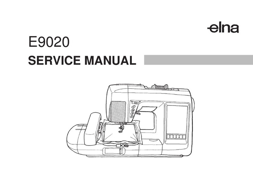
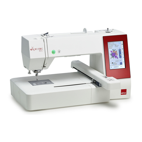
ELNA eXpressive920 User manual

SERVICE MANUAL
eXpressive920
First Edition 01 September 2015

TABLE OF CONTENTS
Replacing External Parts
Face cover .................................................................................................................................................................1
Belt cover ..................................................................................................................................................................1
Top cover unit ............................................................................................................................................................2
Base plate..................................................................................................................................................................3
Base cover.................................................................................................................................................................3
Bed cover ..................................................................................................................................................................3
Free arm cover ..........................................................................................................................................................4
Front cover.................................................................................................................................................................5
Rear cover .................................................................................................................................................................6
Replacing Mechanical Parts
Needle threader holder (threader hook) ....................................................................................................................7
Replacing Electronic Components
Printed circuit board A ...............................................................................................................................................8
Printed circuit board U1.............................................................................................................................................9
Printed circuit board U2...........................................................................................................................................10
Printed circuit board K .............................................................................................................................................11
Printed circuit board F .............................................................................................................................................12
Auxiliary power supply unit......................................................................................................................................13
Switching power supply unit ....................................................................................................................................14
USB unit ..................................................................................................................................................................15
Driving motor ...........................................................................................................................................................16
Thread tension unit..................................................................................................................................................17
Needle threader motor.............................................................................................................................................18
Mechanical Adjustment
Feed dog height.......................................................................................................................................................19
Needle drop position................................................................................................................................................20
Hook Timing.............................................................................................................................................................21
Needle bar height ....................................................................................................................................................22
Clearance between needle and tip of rotary hook............................................................................................. 23-24
Backlash between hook drive gear and lower shaft gear ........................................................................................25
Upper shield plate position ......................................................................................................................................26
Upper thread tension...............................................................................................................................................27
Tension release mechanism ....................................................................................................................................28
Needle threader hook position.................................................................................................................................29
Thread drawing lever...............................................................................................................................................30
Upper feed dog.................................................................................................................................................. 31-33
Buttonhole lever adjustment ....................................................................................................................................34
Thread cutter ...........................................................................................................................................................35
Presser bar lifter position.........................................................................................................................................36
Presser foot lifter stopper position ..................................................................................................................... 37-39
Automatic presser foot lifter initializing sensor position ...........................................................................................40
Presser bar height ...................................................................................................................................................41
Embroidery foot height ............................................................................................................................................42
Stretch stitch balance ..............................................................................................................................................43
Knee lifter ................................................................................................................................................................44
Remaining bobbin thread sensor.............................................................................................................................45
Cloth guide start position.........................................................................................................................................46
Preparation ........................................................................................................................................................ 47-50
• Removing Y-carriage cover (upper) ...................................................................................................................... 47
• Removing X-carriage cover and Embroidery unit cover.................................................................................. 48-50
Replacing X-motor.................................................................................................................................................. 51
Replacing Y-motor............................................................................................................................................. 51-56
• Removing Y-carriage cover (lower)................................................................................................................. 51-52
• Removing Film ..................................................................................................................................................... 52
• Removing Film guides.......................................................................................................................................... 53
• Removing Y-carriage ...................................................................................................................................... 53-54
• Removing Y-motor .......................................................................................................................................... 55-56
Replacing Printed Circuti Board S1........................................................................................................................ 57
Replacing Embroidery Unit Detecting Switch......................................................................................................... 57
Replacing Film........................................................................................................................................................ 58
Replacing X-sensor .......................................................................................................................................... 59-60
Replacing X-belt ..................................................................................................................................................... 61
Replacing Printed Circuit Board S2........................................................................................................................ 62
Replacing Y-sensor ................................................................................................................................................. 62
Replacing Y-belt ...................................................................................................................................................... 63
Carriage Adjustment (Backlash of Y-carriage) ........................................................................................................ 64
1
Replacing External Parts (1)
Face cover
To remove:
1. Open the face cover.
Disconnect the connector.
2. Remove the setscrews A (2 pcs.).
Remove the face plate.
To attach:
1. Follow the above procedure in reverse.
Belt cover
To remove:
1. Remove the caps.
2. Remove the setscrews B and C.
Connector
Face cover
Caps
Setscrews B
Setscrew D
Setscrew C
Setscrew E
3. Loosen the setscrew D.
4. Loosen the setscrew E.
Remove the belt cover.
To attach:
Follow the above procedure in reverse.
NOTE:
The setscrew C is tapping screw.
Setscrews A

2
Replacing External Parts (2)
Top cover unit
To remove:
1. Open the top cover.
Remove the setscrews A and B.
2. Close the top cover.
Raise the carrying handle.
Remove the setscrew C.
5. Detach the top cover for the machine.
Be careful not to pull the bobbin winder motor cords.
Disconnect the connector from the printed circuit board U1.
Remove the top cover.
To attach:
Follow the above procedure in reverse.
Be careful not to pinch the cords when atttaching the top cover
to the machine.
Setscrew A
Setscrew B
Setscrew C
Connector
3. Pry up the front edge of the top cover body to unhook it
from the front cover.
4. Lift the top cover unit and draw it out to the left.
Bobbin winder motor cords

3
Base plate
To remove:
1. Remove the setscrews A (3 pcs.).
2. Remove the setscrews B (2 pcs.).
3. Remove the base plate.
To attach:
Follow the above procedure in reverse.
Replacing External Parts (3 )
Setscrews A
Setscrew A
Setscrew B
Setscrew B
Base cover
To remove:
1. Remove the extension table.
2. Remove the setscrews C (4 pcs.).
Remove the setscrews D (3 pcs).
Remove the base cover.
To attach:
Follow the above procedure in reverse.
Base plate
Bed cover
To remove:
1. Remove the extension table.
2. Remove the setscrews E (2 pcs).
Remove bed cover.
To attach:
1. Follow the above procedure in reverse.
Setscrews E
Bed cover
Setscrews C
Setscrews C
Setscrews D
Base cover

4
Replacing External Parts (4)
Hook A Hook C
Free arm cover
To remove:
1. Remove the presser foot. Push down the needle plate
release lever to remove the needle plate.
Remove the bed cover (see page 3).
2. Remove the threaded pin.
3. Loosen the setscrew and unhook the hook A by sliding
the free arm cover to the left.
4. Pull the free arm cover to the left and lift the part B to clear
the needle palte base, and remove the free arm cover.
To attach:
1. Place the free arm cover on the free arm inserting the
hook C into the opening.
2. Insert the right end of the free arm cover under the
front cover by pushing the right end. Push the free arm
cover until all the hooks and tabs snap in place.
3. Follow the steps 1 to 3 of removal procedure in reverse.
Needle plate release lever
Needle plate
Pin
Hook A
Setscrew
BNeedle plate base

5
Front cover
Hole G
Replacing External Parts (5)
Hole H
Front cover
To remove:
1. Remove the belt cover and top cover (see pages 1 and 2).
2. Loosen the setscrews (A, B, C, D, E and F).
3. Push down the rear cover through the holes (G and H)
with a screwdriver to unhook it from the front cover.
4. Disconnect the all connectors. Remove the front cover.
To attach:
Follow the above procedure in reverse.
Setscrew A
Setscrew B
Setscrew C
Setscrew D
Setscrew E Setscrew F

6
Replacing External Parts (6)
Connector Setscrew A
Face cover
Setscrew B
Rear cover
To remove:
1. Remove the belt cover, top cover and base cover (see
page 1, 2 and 3).
2. Open the face plate and disconnect the connector.
3. Loosen the setscrews A and B.
4. Remove the setscrews C (2 pcs.) and D (2 pcs).
Setscrews C
Setscrew D
Holes E
5. Push down the rear cover through the holes E to unhook it
from the front cover.
6. Remove the rear cover.
To attach:
Follow the above procedure in reverse.

7
Replacing Mechanical Parts
Needle threader holder (threader hook)
To remove:
1. Loosen the setscrew to remove the needle threader
holder.
2. Disassemble the threader unit and replace the threader
hook. Refer the following part number when ordering service
parts.
862627005: Hook holder (unit)
To attach:
1. Assemble the threader unit as illustrated and attach them to
the threader shaft by inserting the shaft into the holes.
Make sure the pin is engaged in the slot.
2. Secure the threader unit to the threader shaft by tightening
setscrew.
Adjust the needle threader hook position (see page xx).
Setscrew
Hook holder (unit) (862627005)
Setscrew
Slot
Pin

8
Driving motor
Phase sensor
Board A schematic
Printed circuit board U1 relay (24-pin)
Printed circuit board U2 relay (18-pin)
Printed circuit board U2 relay (20-pin)
Knee lifter sensor
LCD
Printed circuit board U1 relay (26-pin)
Printed circuit board B (USB board)
Foot control
Replacing Electronic Components
Printed circuit board A
NOTE:
Do not disconnect the connectors by pulling on cord.
To disconnect the connectors, grasp the connector, not the
cord.
To remove:
1. Remove the front cover (see page 5).
2. Disconnect the connectors. Remove the setscrews
(4 pcs.) and printed circuit board A.
To attach:
Follow the above procedure in reverse.
After replacing the printed circuit board A, adjust the following
parts:
• Knee Lifter (see page 48)
• Cloth guide start position (see page 53)
• Remaining bobbin thread sensor (see page 49)
• Presser bar height (see page 44)
• Embroidery foot height (see page 45)
* Adjust the embroidery foot height after the presser bar
height adjustment.
Printed circuit board A
Setscrew
Printed circuit board K1 relay (6-pin)
Printed circuit board K1 relay (26-pin)
Printed circuit board K1 relay (30-pin)
Printed circuit board U2 relay (14-pin)
TTP (Touch panel)
LCD module
Switching power supply unit
Auxiliary power supply unit
Setscrew
Setscrew
Setscrew

9
Printed circuit board U1
Board U1 schematic
Buttonhole sensor
Presser foot lifter switch
No connection
Thread tension motor
Zigzag motor
Relay cable (2-pin)
Printed circuit board A relay
(24-pin)
Replacing Electronic Components
Printed circuit board U1
NOTE:
Do not disconnect the connectors by pulling on cord.
To disconnect the connectors, grasp the connector, not the
cord.
To remove:
1. Remove the top cover (see page 2).
2. Disconnect the connectors. Remove the setscrews
(2 pcs.) and printed circuit board U1.
To attach:
Follow the above procedure in reverse.
LED (white)LED (Blue)
Printed circuit board
A relay (26-pin)
Needle threader motor
Bobbin winder motor
Presser foot lifter motor Thread cut detection
Setscrew
Setscrew

10
Bobbin thread sensor
potentiometer
Needle plate sensor switch
Printed circuit board A relay
(18-pin)
Feed motor
Printed circuit board A relay
(14-pin)
Bobbin thread sensor motor
Drop feed motor
Printed circuit board A relay
carriage
Relay (carriage)
Thread cutter motor
Replacing Electronic Components
Printed circuit board U2
NOTE:
Do not disconnect the connectors by pulling on cord.
To disconnect the connectors, grasp the connector, not the
cord.
To remove:
1. Remove the base plate (see page 3).
2. Remove the setscrew A and cord binder. Disconnect the
connectors.
3. Disconnect the connectors and setscrews B.
Remove the printed circuit board U2.
To attach:
Follow the above procedure in reverse.
Setscrew A
Cord binder
Setscrews B (3 pcs.)
Printed circuit board U2
Board U2 schematic

11
Printed circuit board K
NOTE:
Do not disconnect the connectors by pulling on cord.
To disconnect the connectors, grasp the connector, not the
cord.
To remove:
1. Remove the front cover (see page 5).
2. Disconnect the connectors from the circuit board K.
3. Remove the setscrews (3 pcs), and the circuit board K.
To attach:
Follow the above procedure in reverse.
Replacing Electronic Components
Circuit board K schematic
Printed circuit board F
Printed circuit board L1
Slide volume
Printed circuit board L2
Printed circuit board
A relay 6-pin)
Printed circuit board
A relay (26-pin)
Printed circuit board
A relay (30-pin)
Setscrew Setscrew

12
Setscrews
Connector A Printed circuit
board F
Printed circuit board F
To remove:
1. Remove the front cover (see page 5).
2. Disconnect the connector A from the circuit board K.
Remove the sticky tapes (2 places).
3. Remove the setscrews (2 pcs), and the circuit board F.
To attach:
1. Follow the above procedure in reverse.
2. Fix the connector cords with sticky tapes (Sekisui Chemical
Polyesper Type 900 or 3M 44D-A Electrical Tape)
Replacing Electronic Components
Sticky tape

13
Auxiliary power supply case unit
To remove:
1. Remove the belt cover, top cover, front cover and the rear
cover (see pages 1, 2, 5 and 6).
2. Disconnect the connector of the auxilliary power supply
unit from the printed circuit board A (see page 8).
Cut the tie band of the ferrite core and remove the cords
from the board.
3. Disconnect the connector from the case.
4. Remove the setscrews (2 pcs.).
5. Remove the auxiliary power supply case unit from the
machine.
To attach:
Follow the above procedure in reverse.
Replacing Electronic Components
Setscrew
Connector
Auxiliary power supply case unit
Ferrite core
Tie band
Setscrew

14
Switching power supply unit
To remove:
1. Remove the belt cover, top cover, front cover and the rear
cover (see pages 1, 2, 5 and 6).
2. Remove the auxilliary power supply case unit (see page
13).
3. Disconnect the switching power supply connector from the
printed circuit board A. Draw out the connector from the
opening and remove the connector cords from the cord
guide.
4. Remove the setscrews B (top of the machine).
5. Disconnect the connector C from the switching power
supply unit.
6. Remove the setscrews D and E.
6. Remove the setscrew F and remove the switching power
supply unit.
To attach:
Follow the above procedure in reverse.
Setscrew B
Replacing Electronic Components
Connector C
Cord guide
Connector cords
To board A
Setscrew D
Setscrew E
Setscrew F
Opening

15
Ferrite core
USB unit
To remove:
1. Remove the belt cover, top cover and the front cover (see
pages 1, 2 and 5).
2. Disconnect the the USB unit connector from the printed
circuit board A (see page 8).
Cut the tie band of the ferrite core.
3. Lay the machine on its back. Remove the setscrews (2
pcs.).
4. Remove the USB unit from the machine.
To attach:
Follow the above procedure in reverse.
Replacing Electronic Components
Setscrews
Tie band
USB unit
To board A
USB unit

16
200 g pressure
5 mm
Setscrews
Replacing Electronic Components
DC motor
To remove:
1. Remove the belt cover, the top cover and the front cover
(see pages 1, 2, and 5).
2. Detach the ferrite core (fixed with a sticky tape) from the
base plate for ferrite cores.
3. Disconnect the DC motor connector from the printed circuit
board A.
Setscrews
4. Remove the 2 setscrews. Remove the driving motor.
To attach:
1. Put the motor belt on the motor pulley.
2. Attach the DC motor and slightly tighten the setscrews F.
2. Adjust the belt tension.
Push the middle of the belt span with approximately
200 grams pressure. Adjust the motor position so that
the belt deflects 5mm.
3. Tighten the setscrews F securely.
4. Connect the DC motor connector to the printed circuit
board A.
5. Fix the ferrite core to the base plate for ferrite cores with a
sticky tape (Sekisui Chemical Polyester Type 900 or 3M
44D-A Electrical Tape). Attach the front cover, the top cover
and the belt cover.

17
Replacing Electronic Components
Setscrew C
Thread tension unit
To remove:
1. Remove the belt cover and the top cover (see page 1 and 2).
2. Remove the front cover (see page 5).
3. Remove the setscrew A and cord guide. Remove the
setscrew B and shield guide plate. Cut the 3 tie bands.
4. Disconnect the thread cut detection connector and thread
tension motor connector from the printed circuit board U1
(see page 9).
5. Remove the setscrews C and D. Remove the thread
tension (unit).
To attach:
1. Follow the above procedure in reverse.
2. Adjust the tension release mechanism (see page 28).
Check the upper thread tension (see page 27).
Setscrew D
Thread tension unit
Setscrew ACord guide
Cord guide

18
Replacing Electronic Components
Motor cover
Setscrew A
Setscrew B
Needle threader motor
To remove:
1. Remove the top cover (see page 2).
Disconnect the connector form the face cover.
2. Loosen the setsrew A.
Connector
6. Disconnect the connector of the needle threader motor
from the printed circuit board U1 (see to page 9).
Remove the spiral cord binder and separate the needle
threader motor cords from other cords.
Remove the setscrews D.
Remove the motor and the needle threader unit.
To attach:
1. Place the needle threader motor unit inserting the actuator
tab in the recess of the threader arm.
Follow the above procedure in reverse.
2. Adjust the needle threader hook position (see page 29).
Threader arm
Actuator tab
3. Remove the setscrew B and remove the motor cover.
Setscrews D
Needle threader motor cords Spiral cord binder
Connector
Table of contents
Other ELNA Sewing Machine manuals

ELNA
ELNA eXcellence 710 User manual

ELNA
ELNA 3210 User manual

ELNA
ELNA Creative Series User manual

ELNA
ELNA 5200 User manual

ELNA
ELNA TX User manual

ELNA
ELNA 6003 - LEAFLET User manual

ELNA
ELNA eXperience 660 User manual

ELNA
ELNA 7300 - User manual

ELNA
ELNA 664 - User manual

ELNA
ELNA eXcellence 760 User manual

ELNA
ELNA eXcellence 680 User manual

ELNA
ELNA Lotus User manual

ELNA
ELNA 2000 Series User manual

ELNA
ELNA eXperience 580 User manual

ELNA
ELNA 6005 heirloom edition User manual

ELNA
ELNA 5300 - User manual

ELNA
ELNA 3210 User manual

ELNA
ELNA Air Artist Installation guide

ELNA
ELNA EC 11 User manual

ELNA
ELNA eXperience 550 User manual