Elnur Gabarron SOLAR BOX USB Mounting instructions

ES
Por favor, lea estas instrucciones atentamente antes de instalar o utilizar el equipo por primera vez.
Please read these instructions carefully before installing or using this appliance for the first time.
INSTRUCCIONES DE INSTALACIÓN Y USO
INSTALLATION INSTRUCTIONS AND USER GUIDE
GESTOR DE EXCEDENTES FOTOVOLTAICOS
ACUMULADORES ELNUR GABARRON
ENERGY SOLAR MANAGER FOR
STORAGE HEATERS ELNUR GABARRON
SOLAR BOX

1
ES
1. CONTENIDO DE LA CAJA
-1 x Este manual
-1 x Centralita G Control Hub EU con adaptador de corriente y cable ethernet.
-2 x Medidor de potencia G Control PM. (Medidor + Transformador de intensidad)
2. INSTALACION
2.1. Instalación Medidores de potencia G Control PM.
Instale los 2 medidores de potencia AC suministrados según el esquema mostrado:
-Medidor de consumo. El primer medidor registrando el consumo total de la vivienda.
-Medidor de generación. El segundo medidor registrando la generación fotovoltaica después del
inversor (AC), es decir, con la pinza amperimétrica abrazando el cable de fase que conecta con el
inversor.

2
ES
Siga las siguientes instrucciones para la instalación de cada uno de los medidores G Control PM. (Generación
y Consumo)
Desconecte el interruptor general automático del cuadro de mando y protección
de su vivienda previamente a la instalación.
Desconecte el inversor y la generación fotovoltaica previamente a la instalación.
Advertencia: El medidor de potencia G Control PM es un medidor AC monofásico.
El dispositivo G Control PM está preparado para su instalación en el cuadro de mando y protección.
a. Instale el dispositivo en el carril DIN del cuadro de mando y protección.
b. Conecte el dispositivo utilizando el cableado oportuno a una alimentación de 230V.
c. Conecte el medidor de intensidad al dispositivo G Control PM y abrace con la pinza de medición:
1. Medidor de consumo. El cable principal de consumo de la vivienda para que registre el consumo
total de la vivienda.
Advertencia: El medidor de consumo se instala registrando el consumo total de la vivienda como
se muestra en el gráfico anterior, independientemente del origen de la energía consumida
(Fotovoltaica o red). No debe ser instalado en el mismo punto que el medidor de la compañía.
2. Medidor de Generación. El cable de fase de conexión del inversor al cuadro de mando y
protección para medir la generación fotovoltaica.
2.2. Instalación Centralita G Control Hub EU
1. Conecte la centralita G Control Hub a internet utilizando el cable ethernet suministrado.
2. Conecte la centralita G Control Hub a la alimentación utilizando el adaptador de corriente
suministrado.
3. Espere y observe el estado de las luces LED hasta corroborar la correcta conexión de la centralita
con el router.
Estado LEDS
Descripción
Verde apagado, naranja
intermitente cada segundo.
Centralita en modo descubrimiento para emparejamiento con
dispositivos
Naranja encendido, verde
intermitente muy rápido
El router no asigna IP válida a la Centralita
Naranja encendido, verde parpadea
cada 5 segundos
La centralita dispone de una IP asignada, pero no hay comunicación
con el servidor.
Naranja encendido, alterna con
verde cada 5 segundos
Centralita dispone de IP asignada y comunica correctamente con el
servidor.
CUADRO DE
MANDO Y
PROTECCIÓN
SEÑAL RF

3
ES
3. REGISTRO Y CONFIGURACIÓN DE LA INSTALACIÓN. APLICACIÓN MÓVIL
3.1 Aplicación Elnur Gabarron Solar Control
El registro y creación de una cuenta de usuario es
necesario para el control remoto de su instalación
y para la configuración y gestión de los
excedentes fotovoltaicos. Si no dispone de una
cuenta de usuario, el primer paso es registrarse
en el portal a través de la web
https://remotesolar.elnur.es o desde la aplicación
Elnur Solar Control disponible en App Store y
Play Store.
Introduzca una dirección de correo electrónico
válida, que deberá verificar, y una contraseña de
acceso. Se enviará automáticamente un email a su
bandeja de entrada para verificar la dirección de
correo solicitada.
3.2 Creación de Vivienda. Alta de Centralita G Control HUB EU
Una vez creada y confirmado su cuenta de correo electrónico, acceda a la aplicación con sus datos. El
asistente le guiará para dar de alta su instalación.
Introduzca el nombre de su vivienda.

4
ES
Seleccione la franja horaria y en el paso siguiente el tipo de dispositivo y siga las instrucciones del asistente.
En el siguiente paso, el asistente le pedirá pulsar el botón situado en la parte posterior de la centralita G
Control HUB EU para localizarla y asociar automáticamente la cuenta registrada con el ID del dispositivo G
Control Hub. Para ello, la centralita G Control Hub debe estar previamente conectada con el código de luces
correcto, y el dispositivo móvil desde el que está realizando la configuración debe estar conectado a la red
Wifi generada por el mismo router al que está conectada la centralita.
En caso de no estar conectado a la misma red wifi, después de varios segundos, se abortará la detección
automática, permitiendo al usuario la introducción manual del ID del dispositivo, código alfanumérico de 18
posiciones, que podrá encontrar en la pegatina de la parte inferior del dispositivo y en el embalaje original del
mismo.

5
ES
Como último paso, asigne un nombre a su vivienda cuando se lo indique el asistente, y configure la tarifa
energética en función de la tarifa contratada con su compañía eléctrica. Por defecto, están preconfiguradas las
2 tarifas de discriminación horaria más habituales en España:
-España (Horaria de invierno). Con periodo valle de 22:00 a 12:00
-España (Horario de verano). Con periodo valle de 23:00 a 13:00
Posteriormente, una vez registrada la vivienda, puede modificar la tarifa si ésta no coincide con ninguna de las
preconfiguradas.
La instalación de la centralita G Control Hub EU ha finalizado.
3.3 Vinculación de medidores G Control PM.
El último paso a realizar para finalizar la configuración y alta de la SOLAR BOX es la vinculación y alta en la
aplicación de los dos medidores instalados (Medidor de consumo y medidor de generación). Para ello, siga los
siguientes pasos:
-Abra la aplicación y acceda al menú de calefacción del menú inferior de la aplicación.
-Pulse ahora el botón flotante (añadir) y seleccione el dispositivo a instalar. (Medidor)

6
ES
Presione comenzar búsqueda y siga las instrucciones del asistente,
pulsando con un clip en el pequeño pulsador situado en la parte
superior del medidor.
Puede comprobar el estado del medidor en función del pequeño LED frontal.
Estado LEDS
Descripción
LED apagado
No emparejado
LED pardeando cada 2 segundos
Emparejado correctamente
LED parpadea cada medio segundo
Emparejado con la centralita, pero
perdida la conexión con la misma.
Como último paso, se le pedirá asignar un nombre al medidor
G Control PM instalado y seleccionar el tipo de circuito:
Generación o Consumo.
Estos ajustes pueden ser modificados posteriormente en la
sección Configurar de cada medidor instalado.
Una vez vinculados los dos medidores, la instalación y registro
de la SOLAR BOX ha finalizado.
4. RESOLUCIÓN DE PROBLEMAS
La Centralita no conecta
Revise el estado de conexión a través de los Leds indicadores de la
Centralita.
Revise que se encuentra alimentada y conectada correctamente a
internet a través de la toma Ethernet sin un proxy y con los puertos
123UDP, 5000TCP y 5001 TCP abiertos. El router ha de tener DHCP
activado.

7
EN
1. CONTENTS
-1 x This Manual
-1 x G Control Hub EU Smart-box, power adapter and ethernet cable
-2 x G Control PM Power Meter (Meter + Current transformer)
2. INSTALLATION
2.1. G Control PM installation
Install the 2 G Control PM meters following the below wiring diagram.
-Home Consumption power meter. Install one G Control PM measuring the power consumption of the
home.
-PV Generation meter. Install the other G Control PM measuring the energy generated by the Solar PV
installation. This meter must be installed after the inverter measuring the energy in the AC side.

8
EN
Follow the below instructions for the installation of the G Control PM power meters. (PV generation and
home consumption)
Disconnect the main switch of the consumer unit prior to the device installation.
Disconnect the inverter and the PV generation before the device installation.
Warning: The G Control PM is valid only for single-phase installations.
The G Control PM device is prepared to be installed in the consumer unit of your home.
a. Install the device on the DIN rail in the consumer unit of your home.
b. Connect the device using the appropriate wiring to a 230 V power supply.
c. Connect the clamp energy meter to the G Control PM device and embrace:
1. Home consumption meter. The main cable at the output of the main switch to record the total
energy consumption.
Warning: The home consumption meter is installed measuring the total consumption of the
home as it is shown in the diagram of the previous page. It must not be installed in the same point
than the company smart meter.
2. PV Generation meter. The line connection cable from the PV inverter to the consumer unit of
your home to register the PV generation.
2.2. G Control Hub EU Smart-box installation.
1. Connect the G Control Hub to internet using the supplied ethernet cable.
2. Connect the G Control Hub to the electricity supply using the supplied power adapter.
3. Wait and check the status of LED lights to confirm the correct connexion between the G Control
Hub and the router.
LEDS Status
Description
Green off, orange blinking every
second.
G Control Hub in discovery mode for devices being associated.
Orange on, green blinking very fast
The router does not assign a valid IP to the G Control Hub.
Orange on, green blinking every
5 seconds
A valid IP is assigned to G Control Hub, but there is no
communication with the server.
Orange on, green alternating every
5 seconds
A valid IP is assigned to G Control Hub and it communicates
successfully with the server.
RF SIGNAL

9
EN
3. REGISTERING IN APP-WEB AND CONFIGURATION SETTING.
3.1 Elnur Gabarron Solar Control Application
Registering and creating a user account is
required for remote control and energy
management of your installation via internet. If
you do not have a user account, the first step is
to register in the portal using the website
https://remotesolar.elnur.es or using the app
Elnur Gabarron Solar Control available in App
Store for IOS and Play Store for Android.
Enter a valid email address, that must be
verified, and a password. An email will be
automatically sent to your inbox to verify the
registered email.
3.2 New home. Adding a new G Control Hub EU
Enter the app using your email account and password and follow the instructions of the installation wizard to
add a new home.
First, set the name of your new home.

10
EN
Now, select the home time zone and follow the instructions of the installation wizard.
Note: The G Control Hub EU device must be correctly connected to the power supply and to the internet
before moving on with the installation process.
In the following step, the installation wizard will ask to press the button located at the back of the G Control
Hub Smartbox for automatic detection and association of the Smarbox with your user account.
Note: The automatic detection of the Smartbox will only work if the smartphone or tablet used for the
process and the G Control Hub device are connected to the same internet network.
If the smart phone or tablet and the G Control Hub EU are not connected to the same network, the
automatic detection will be discontinued after some seconds, allowing the user to manually introduce the G
Control Hub Identification. Smartbox ID is an 18 alphanumeric code that can be found in a label in the bottom
part of the Smartbox or in the serial number label in the packaging of the unit.

11
EN
In the last step of the installation, set a name for your Smartbox when required and set your current
electricity tariff. By default, 2 pre-set off-peak tariff are available:
-Spain (Winter Time). Off-peak period every day from 22:00 to 12:00
-Spain (Summer Time). Off-peak period every day from 23:00 to 13:00
Later, once registered your home, the electricity tariff can be modified if your tariff is different to the default
ones.
The G Control Hub EU installation is over.
3.3 G Control PM association.
The last step to finish the installation of the SOLAR BOX is the link and association of the G Control PM
power meters previously installed (Generation and Home Consumption meters) to the app. Follow the next
steps to associate the meters:
-Open the app and enter the Heating menu at the bottom of the screen.
-Press the “Add” button and select the type of device that you are going to install (Meter).

12
EN
Press “Star Search” button and use a clip to press the small button
placed at the top of the meter.
You can check that the meter has been linked by looking at the device LED.
LEDS Status
Description
LED off
Not linked
LED flashing every 2 seconds
Correctly linked
LED flashing every half a second
Correctly linked with the G Control
Hub, but currently lost the connection
The last step is to set a name for the meter and select the type
of circuit to indicate if the meter that is being linked is PV
generation or home consumption meter.
These settings can be modified later in the Config section of
the G Control Power Meters.
Once linked both meters, the installation of the SOLAR BOX
has finished.
4. TROUBLESHOOTING
G Control HUB EU does
not connect to the
internet.
Check the LEDS light of the hub that indicates the connection status.
Check the power supply and the internet connection. An internet
connection without a proxy and the ports 123UDP, 5000TCP and 5001
TCP opened are required. Router must have DHCP option activated.

13
NOTAS / NOTES

14
NOTAS / NOTES

Como parte de la política de mejora continua, Elnur, s.a. se reserva el derecho a realizar modificaciones
técnicas sin previo aviso.
As a part of the policy of continuous product improvement Elnur, s.a. reserves the right to alter
specifications without notice.
ELNUR S.A.
Travesía de Villa Esther, 11
28110 Algete - Madrid
Tfno. Atención al Cliente
Customer Service Telephone
+34 91 628 1440
www.elnurgabarron.es
www.elnurgabarron.com
www.elnur.co.uk
30200268 R2
Other manuals for SOLAR BOX USB
1
Table of contents
Languages:
Other Elnur Gabarron Control Unit manuals
Popular Control Unit manuals by other brands
Allen-Bradley
Allen-Bradley POINT I/O 1734-PDN installation instructions
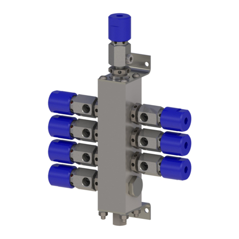
Carlisle
Carlisle BINKS 240-5100 Service manual
Bradley
Bradley TouchTime S45-1941 Installation

Meinberg
Meinberg IMS SCG180-U Setup guide
Tews Technologies
Tews Technologies TPMC461 user manual

American Standard
American Standard SELECTRONIC 6065.521 installation instructions

