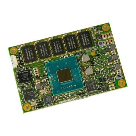
Avnet Qseven MSC Q7-BT User manual

Qseven® Compact Module
MSC Q7-BT
Qseven® 2.0 Pinout
Intel® Atom™Series SOC
Rev. 1.12 06/12/2020
User Manual

MSC Q7-BT MSC_Q7-BT_User_Manual.pdf 2 / 113
PREFACE
Copyright Notice
Copyright © 2015 MSC Technologies GmbH. All rights reserved.
Copying of this document, and providing to others and the use or communication of the contents thereof, is forbidden without
express authority of MSC Technologies GmbH. Offenders are liable to the payment of damages.
All rights are reserved in the event of the grant of a patent or the registration of a utility model or design.
Important Information
This documentation is intended for qualified audiences only. The product described herein is not an end user product. It was
developed and manufactured for further processing by trained personnel.
Disclaimer
Although this document has been generated with the utmost care no warranty or liability for correctness or suitability for any
particular purpose is implied. The information in this document is provided “as is” and is subject to change without notice.
EMC Rules
This unit has to be installed in a shielded housing. If not installed in a properly shielded enclosure, and used in accordance
with the instruction manual, this product may cause radio interference in which case the user may be required to take
adequate measures at his or her owns expense.
Trademarks
All used product names, logos or trademarks are property of their respective owners.

MSC Q7-BT MSC_Q7-BT_User_Manual.pdf 3 / 113
Certification
MSC Technologies GmbH is certified according to DIN EN ISO 9001:2000 standards.
Life-Cycle-Management
MSC products are developed and manufactured according to high quality standards. Our life-cycle-management assures long
term availability through permanent product maintenance. Technically necessary changes and improvements are introduced if
applicable. A product- change-notification and end-of-life management process assures early information of our customers.
Product Support
MSC engineers and technicians are committed to provide support to our customers whenever needed.
Before contacting Technical Support of MSC Technologies GmbH, please consult the respective pages on our web site at
www.msc-technologies.eu for the latest documentation, drivers and software downloads.
If the information provided there does not solve your problem, please contact our Technical Support:
Phone: +49 - 8165 906 - 200
Fax: +49 - 8165 906 - 201
Email: support@msc-technologies.eu

MSC Q7-BT MSC_Q7-BT_User_Manual.pdf 4 / 113
CONTENTS
1INTRODUCTION ..................................................................................................................................................................................................11
1.1 Key Features........................................................................................................................................................................................................................11
1.2 Block Diagram......................................................................................................................................................................................................................16
1.3 Power Supply.......................................................................................................................................................................................................................17
1.4 Power Dissipation.................................................................................................................................................................................................................18
1.5 Mechanical Dimensions........................................................................................................................................................................................................20
2THERMAL SPECIFICATIONS..............................................................................................................................................................................21
2.1 Heatspreader Concept .........................................................................................................................................................................................................21
2.2 Thermal Definitions ..............................................................................................................................................................................................................22
2.3 Thermal Management ..........................................................................................................................................................................................................24
2.4 Power Management .............................................................................................................................................................................................................25
2.5 Use Conditions.....................................................................................................................................................................................................................25
3MODULE CONNECTOR PINOUT........................................................................................................................................................................26
4MODULE CONNECTOR SIGNAL DESCRIPTION...............................................................................................................................................29
4.1 High Definition Audio............................................................................................................................................................................................................29
4.2 Ethernet...............................................................................................................................................................................................................................30
4.3 Serial ATA............................................................................................................................................................................................................................31
4.4 PCI Express.........................................................................................................................................................................................................................32
4.5 USB.....................................................................................................................................................................................................................................33
4.6 LVDS ...................................................................................................................................................................................................................................35
4.7 eDP......................................................................................................................................................................................................................................37
4.8 Dual Mode Display Port (DP++)............................................................................................................................................................................................37
4.9 SPI Bus................................................................................................................................................................................................................................38
4.9.2 Off-module BIOS implementation for MSC Q7-BT................................................................................................................................................................................39
4.9.3 Customer SPI-Bus based on Intel® Atom™ E3800 Product Family ......................................................................................................................................................39
4.10 LPC Bus...............................................................................................................................................................................................................................40
4.11 SDIO....................................................................................................................................................................................................................................40
4.12 UART...................................................................................................................................................................................................................................41
4.13 I²C........................................................................................................................................................................................................................................41
4.13.1 I²C Resources on the Module..............................................................................................................................................................................................................41
4.14 Watchdog.............................................................................................................................................................................................................................42
4.15 Fan ......................................................................................................................................................................................................................................42
4.16 System Management............................................................................................................................................................................................................43
4.17 SM Bus................................................................................................................................................................................................................................44

MSC Q7-BT MSC_Q7-BT_User_Manual.pdf 5 / 113
5FUNCTIONS ON MODULE ..................................................................................................................................................................................45
5.1 RTC.....................................................................................................................................................................................................................................45
5.2 Solid State Drive (SSD)........................................................................................................................................................................................................45
5.3 eMMC..................................................................................................................................................................................................................................46
6SYSTEM RESOURCES........................................................................................................................................................................................47
6.1 PCI Interrupt Routing............................................................................................................................................................................................................47
6.2 IRQ Lines.............................................................................................................................................................................................................................48
6.2.1 Legacy IRQ Mode...............................................................................................................................................................................................................................48
6.2.2 APIC Mode.........................................................................................................................................................................................................................................49
7BIOS.....................................................................................................................................................................................................................51
7.1 Introduction..........................................................................................................................................................................................................................51
7.2 Startup Screen Overview......................................................................................................................................................................................................51
7.3 Activity Detection Background..............................................................................................................................................................................................51
7.4 Aptio Setup Utility.................................................................................................................................................................................................................51
7.5 Configuring the System BIOS...............................................................................................................................................................................................51
7.6 The BIOS Menu Structure ....................................................................................................................................................................................................52
7.6.1 The Menu Bar.....................................................................................................................................................................................................................................53
7.6.2 The Legend Bar..................................................................................................................................................................................................................................54
7.7 The Main Menu....................................................................................................................................................................................................................55
7.7.1 Board Info...........................................................................................................................................................................................................................................56
7.7.2 Hardware Monitoring Measurement.....................................................................................................................................................................................................57
7.7.3 Firmware Update................................................................................................................................................................................................................................58
7.8 The Advanced Menu............................................................................................................................................................................................................59
7.8.1 Trusted Computing (TPM 1.2).............................................................................................................................................................................................................60
7.8.2 Trusted Computing (TPM 2.0).............................................................................................................................................................................................................60
7.8.3 ACPI Settings.....................................................................................................................................................................................................................................61
7.8.4 Serial Port Console Redirection...........................................................................................................................................................................................................61
7.8.5 Console Redirection Submenu............................................................................................................................................................................................................62
7.8.6 CPU Configuration..............................................................................................................................................................................................................................63
7.8.7 PPM Configuration..............................................................................................................................................................................................................................64
7.8.8 IDE Configuration ...............................................................................................................................................................................................................................64
7.8.9 Internal Devices Configuration.............................................................................................................................................................................................................65
7.8.10 AMI Graphic Output Policy..................................................................................................................................................................................................................66
7.8.11 Network Stack Configuration...............................................................................................................................................................................................................66
7.8.12 CSM Configuration .............................................................................................................................................................................................................................67
7.8.13 NVMe.................................................................................................................................................................................................................................................68
7.8.14 SDIO Configuration.............................................................................................................................................................................................................................69
7.8.15 USB Configuration..............................................................................................................................................................................................................................70
7.8.16 Security Configuration.........................................................................................................................................................................................................................71
7.8.17 SIO WB627/ SMSC 311x Configuration...............................................................................................................................................................................................72
7.8.18 EC Hardware Monitoring.....................................................................................................................................................................................................................73
7.8.19 Legacy IRQ Reservation.....................................................................................................................................................................................................................75
7.8.20 Module-specific Initialization................................................................................................................................................................................................................76
MSC Q7-BT MSC_Q7-BT_User_Manual.pdf 6 / 113
7.8.21 I210 Gigabit Connection Settings ........................................................................................................................................................................................................77
7.9 Chipset.................................................................................................................................................................................................................................78
7.9.1 Flat Panel Configuration......................................................................................................................................................................................................................78
7.9.2 Backlight Control.................................................................................................................................................................................................................................79
7.9.3 North Bridge.......................................................................................................................................................................................................................................80
7.9.4 Intel®IGD Configuration......................................................................................................................................................................................................................80
7.9.5 South Bridge.......................................................................................................................................................................................................................................82
7.9.6 Azalia HD Audio .................................................................................................................................................................................................................................83
7.9.7 USB Configuration..............................................................................................................................................................................................................................84
7.9.8 PCI Express Configuration..................................................................................................................................................................................................................85
7.10 Security................................................................................................................................................................................................................................86
7.10.1 Secure Boot........................................................................................................................................................................................................................................86
7.10.2 Key Management................................................................................................................................................................................................................................87
7.11 Boot.....................................................................................................................................................................................................................................88
7.12 Save & Exit ..........................................................................................................................................................................................................................90
8BIOS AND FIRMWARE UPDATE ........................................................................................................................................................................93
8.1 Setup Controlled Update......................................................................................................................................................................................................93
8.2 Bios Update from EFI Shell...................................................................................................................................................................................................94
8.3 Bios Update from Linux ........................................................................................................................................................................................................94
8.4 Bios Update from Windows...................................................................................................................................................................................................94
8.5 Blind Restoration of Bios default settings (no display available) ............................................................................................................................................95
8.6 Bios Recovery......................................................................................................................................................................................................................95
8.7 Bios Recovery (for BIOS version older than V1.50 )..............................................................................................................................................................96
8.8 Clear CMOS and Recovery Jumper......................................................................................................................................................................................97
8.9 Post Codes ..........................................................................................................................................................................................................................97
9TECHNOTES........................................................................................................................................................................................................98
10 EAPI...................................................................................................................................................................................................................102
11 BIOS CONFIGURATOR TOOL..........................................................................................................................................................................103
12 TROUBLESHOOTING .......................................................................................................................................................................................104
Figure 1-1 Block Diagram ..........................................................................................................................................................................................................16
Figure 1-2 Module Dimensions ..................................................................................................................................................................................................20
Figure 2-1 Overall Height including Heatspreader of the Qseven®Module..................................................................................................................................21
Figure 2-2 Measurement points for the thermal probe ................................................................................................................................................................23

MSC Q7-BT MSC_Q7-BT_User_Manual.pdf 7 / 113
Table 1-1 Module Power Inputs ................................................................................................................................................................................................17
Table 1-2 Power Dissipation.....................................................................................................................................................................................................19
Table 2-1 Temperature Range..................................................................................................................................................................................................23
Table 3-1 Module Connector Pinout..........................................................................................................................................................................................26
Table 4-1 HDA Signal Description.............................................................................................................................................................................................29
Table 4-2 Ethernet Signal Description.......................................................................................................................................................................................30
Table 4-3 SATA Signal Description...........................................................................................................................................................................................31
Table 4-4 PCIe Signal Description............................................................................................................................................................................................32
Table 4-5 USB Signal Description.............................................................................................................................................................................................33
Table 4-6 ANX1122 Supported Video Formats..........................................................................................................................................................................35
Table 4-7 LVDS Signal Description...........................................................................................................................................................................................36
Table 4-8 eDP Signal Description.............................................................................................................................................................................................37
Table 4-9 Display Port Signal Description.................................................................................................................................................................................37
Table 4-10 HDMI Signal Description...........................................................................................................................................................................................38
Table 4-11 SPI Signal Description ..............................................................................................................................................................................................38
Table 4-12 Selection of external Boot or customer SPI................................................................................................................................................................39
Table 4-13 LPC Signal Description.............................................................................................................................................................................................40
Table 4-14 SDIO Signal Description............................................................................................................................................................................................40
Table 4-15 UART Signal Description...........................................................................................................................................................................................41
Table 4-16 I²C Signal Description ...............................................................................................................................................................................................41
Table 4-17 Watchdog Signal Description ....................................................................................................................................................................................42
Table 4-18 Fan Signal Description..............................................................................................................................................................................................42
Table 4-19 System Management Signal Description...................................................................................................................................................................43
Table 4-20 SMB Signal Description ............................................................................................................................................................................................44
Table 4-21 Onmodule SMB Addresses.......................................................................................................................................................................................44
Table 5-1 List of available SSD devices....................................................................................................................................................................................45
Table 5-2 List of available eMMC devices.................................................................................................................................................................................46
Table 6-1 PCI Interrupt Routing Table.......................................................................................................................................................................................47
Table 6-2 IRQ Lines in Legacy IRQ Mode.................................................................................................................................................................................48
Table 6-3 IRQ Lines in Legacy APIC Mode...............................................................................................................................................................................49
Table 7-1 BIOS Menu Structure................................................................................................................................................................................................52
Table 7-2 BIOS Menu Bar.........................................................................................................................................................................................................53
Table 7-3 BIOS Legend Bar......................................................................................................................................................................................................54
Table 7-4 BIOS Main Menu.......................................................................................................................................................................................................55
Table 7-5 BIOS MSC Board Info...............................................................................................................................................................................................56
Table 7-6 BIOS Hardware Monitoring Measurement.................................................................................................................................................................57
Table 7-7 BIOS Hardware Monitoring Measurement.................................................................................................................................................................58
Table 7-8 BIOS Advanced Menu...............................................................................................................................................................................................59
Table 7-9 BIOS TPM Menu.......................................................................................................................................................................................................60
Table 7-10 BIOS TPM Menu.......................................................................................................................................................................................................60
Table 7-11 BIOS ACPI Settings..................................................................................................................................................................................................61
Table 7-12 BIOS Serial Port Console Redirection.......................................................................................................................................................................61

MSC Q7-BT MSC_Q7-BT_User_Manual.pdf 8 / 113
Table 7-13 BIOS CPU Menu.......................................................................................................................................................................................................63
Table 7-14 BIOS PPM Configuration...........................................................................................................................................................................................64
Table 7-15 BIOS IDE Configuration............................................................................................................................................................................................64
Table 7-16 BIOS Internal Devices Configuration.........................................................................................................................................................................65
Table 7-17 BIOS AMI Graphic Output Policy...............................................................................................................................................................................66
Table 7-18 BIOS CSM Configuration ..........................................................................................................................................................................................67
Table 7-19 BIOS NVMe..............................................................................................................................................................................................................68
Table 7-20 BIOS SDIO Configuration..........................................................................................................................................................................................69
Table 7-21 BIOS USB Configuration...........................................................................................................................................................................................70
Table 7-22 BIOS Security Configuration......................................................................................................................................................................................71
Table 7-23 BIOS SuperIO Configuration.....................................................................................................................................................................................72
Table 7-24 BIOS EC Hardware Monitoring..................................................................................................................................................................................73
Table 7-25 BIOS Module-specific Initialization ............................................................................................................................................................................76
Table 7-26 BIOS Chipset Menu..................................................................................................................................................................................................78
Table 7-27 BIOS Flat Panel Configuration ..................................................................................................................................................................................78
Table 7-28 BIOS Backlight Control Menu....................................................................................................................................................................................79
Table 7-29 BIOS North Bridge Menu...........................................................................................................................................................................................80
Table 7-30 BIOS Intel®IGD Configuration...................................................................................................................................................................................80
Table 7-31 BIOS South Bridge....................................................................................................................................................................................................82
Table 7-32 BIOS HD Audio Menu...............................................................................................................................................................................................83
Table 7-33 BIOS USB Configuration...........................................................................................................................................................................................84
Table 7-34 BIOS PCI Express Configuration...............................................................................................................................................................................85
Table 7-35 BIOS Security Menu..................................................................................................................................................................................................86
Table 7-36 BIOS Boot Menu.......................................................................................................................................................................................................88

MSC Q7-BT MSC_Q7-BT_User_Manual.pdf 9 / 113
REVISION HISTORY
Rev.
Date
Description
1.0
18.02.2016
Version 1.0 generated
1.1
08.04.2016
Fix PCIe RX power tolerance description
1.2
09.06.2016
Minor corrections
1.3
25.08.2016
Minor corrections
1.4
05.05.2017
Corrected SDIO Mode options
1.5
19.06.2017
Bios chapter Updated
1.6
21.03.2018
Bios chapter updated
1.7
26.03.2018
Bios chapter updated
1.8
10.10.2018
Bios Chapter updated
1.9
22.10.2018
Add WD Info
1.10
12.11.2019
Add comment, SSD, eMMC
1.11
14.05.2020
Changed to Avnet CI
1.12
12.06.2020
Minor corrections

MSC Q7-BT MSC_Q7-BT_User_Manual.pdf 10 / 113
REFERENCE DOCUMENTS
[1] Qseven®Specification
Revision 2.0
Last update: December 8th 2014

MSC Q7-BT MSC_Q7-BT_User_Manual.pdf 11 / 113
1Introduction
Qseven®modules are compact, highly integrated Single Board
Computers.
Typically a Qseven®module consists of a CPU, chipset, memory,
Ethernet controller, BIOS flash, SATA- and USB controller. Interface
controllers or connectors (e.g. RJ45) are implemented on a base board
on to which the Qseven®module can be mounted.
In addition to the power supply PCIe, SATA, USB, LPC etc. interfaces
are present on the connector.
Due to the standardized mechanics and interfaces the system can be
scaled arbitrarily. Despite the modular concept the system design is
very flat and compact.
Qseven®modules require a carrier board to build a working system.
For evaluation purposes MSC recommends the official Qseven®
Reference Platform
1.1Key Features
SoC:
Intel®Atom™E3800 Product Family (Bay Trail)
SDRAM:
up to 4GB DDR3L
soldered on module
optionally ECC
Video:
Dual Channel LVDS 18-bit/24-bit and up to 270MHz pixel clock
Optional embedded Display Port (eDP) depending on BOM variant
Dual Mode Display Port (DP++) (running as packet organized DP or TMDS signal based HDMI/DVI)

MSC Q7-BT MSC_Q7-BT_User_Manual.pdf 12 / 113
Audio:
The MSC Q7-BT module provides a HDA link for audio codec connection.
PCI Express Interface:
3x PCIe x1 Gen. 2.0 ports
Ethernet:
Gigabit Ethernet (Intel®i210) , Vendor ID 8086, Device ID 1533
USB:
4x USB Host ports (USB1.1 and USB2.0)
can be combined with one set of USB3.0 host lane signals
one port shared with USB 2.0 client interface
Depending on BOM variant additional 2 USB host ports provided by a USB hub or USB 3.0 device lanes.
SATA / SATA SSD:
The Bay Trail-I SoC supports two SATA Revision 2.0 ports with data transfer rates of 1.5 Gb/s and 3.0 Gb/s.
If the optional SSD is assembled then only one SATA port is available on the carrier board. For more information see chapter 5.2.
LPC Bus:
The SoC provides a LPC interface based on LPC1.1 specification.

MSC Q7-BT MSC_Q7-BT_User_Manual.pdf 13 / 113
SPI:
Depending on the signal BIOS_DISABLE either SIO SPI or PCU SPI provided by the SoC is switched to the Q7 connector.
PCU SPI is used during BIOS boot up phase, when starting from external BIOS flash on the carrier board.
SIO SPI should be used for customer applications.
I²C Bus:
One of the SoC integrated I²C interfaces is connected to the Qseven®connector.
UART:
Module provides a legacy UART connected to the Qseven®connector
SD Card:
The Intel®Bay Trail SoC provides an SD card interface. The interface is directly routed to the carrier board via the Qseven®connector.
eMMC:
Depending on BOM variant the module provides an eMMC chip. For more information see chapter 5.3.
EEPROM:
An EEPROM is implemented for storing module specific information such as serial number, hardware version etc.
BIOS configuration data is stored in the main BIOS flash.
TPM Support:
For additional security functions a module variant assembled with a Trusted Platform Module can be ordered.
The TPM device on the LPC-Bus is the Infineon SLB9660 chip.

MSC Q7-BT MSC_Q7-BT_User_Manual.pdf 14 / 113
Realtime Clock:
SoC integrated RTC is used.
Watchdog:
Module provides a watchdog
System Monitoring:
Voltage monitoring supported for selected voltages on module.
Temperature measurement at specifc points on the module.
Fan speed monitoring for off module fan connector
Power Management:
Supports Suspend to RAM (S3)
Supports Suspend to Disk (S4)
Supports Soft Off (S5)
Thermal management:
Fan control for off module fan connector
BIOS:
AMI Aptio 5 with TPM support
Supporting boot from SPI-Flash on carrier board or on module.

MSC Q7-BT MSC_Q7-BT_User_Manual.pdf 15 / 113
BIOS SuperIO support:
Winbond 82627 HF
SMSC SCH3112-NU
SMSC SCH3114-NU
EAPI support:
The MSC Q7-BT supports the Embedded Application Programming Interface.
EAPI drivers for various operating systems are available on the MSC technologies support website. (for details see chapter 10)
For more information please contact MSC Technical Support
Phone: +49 - 8165 906 –200
Fax: +49 - 8165 906 - 201
Email: support@msc-technologies.eu

MSC Q7-BT MSC_Q7-BT_User_Manual.pdf 16 / 113
1.2Block Diagram Figure 1-1 Block Diagram

MSC Q7-BT MSC_Q7-BT_User_Manual.pdf 17 / 113
1.3Power Supply
Table 1-1 Module Power Inputs
Power Rail
Description
VCC
Primary power input
Nominal
+5V
Voltage Range
+4.75V ... +5.25V
Max. Input Ripple
±50mV
Max. Voltage Rise rate
< 250V/s
VCC_5V_SB
Standby power input
All available VCC_5V_SB pins on the connector(s) shall
be used.
Used for microcontroller, standby and suspend functions
on the module.
If no standby power is available on carrier board connect
to VCC (primary power input).
Nominal
+5V
Voltage Range
+4.75V ... +5.25V
Max. Input Ripple
±50mV
Rate of Voltage Rising
< 250V/s
VCC_RTC
Real-time clock circuit-power input in system power state
G3 (mechanical off)
Optional; can be left open.
Nominal
+3V
Voltage Range
+2.0V ... +3.3V
Max. Input Ripple
±20mV
Current (G3)
typ. 6 uA; max. 100uA
GND
Power and signal return path. All available GND
connector pins shall be used and tied to Carrier Board
GND plane.

MSC Q7-BT MSC_Q7-BT_User_Manual.pdf 18 / 113
1.4Power Dissipation
Benchmarks used:
Passmark Burn-in Test : 100% CPU, 100% Memory, 100% Graphics 2D, 100% Graphics 3D
Intel TAT stress tool for TDP (Thermal Design Power) and SDP (Scenario Design Power)
The TDP is the maximal power dissipation for the package, this would in normal operation not be achieved, but the test can be used for profiling
thermal solutions for cooling.
The SDP describes a more typical worst case scenario power dissipation.
The measurements below were done on one module only so there may well be variation between different modules and silicon.
Operating System: Windows 7 –64bit
Modules used for the test measurements:
QC (Quad Core)
MSC Q7-BT-45-4001I
Intel Atom E3845 Quad Core 1.91GHz, 10W TDP, 4GB DDR3L, GbE LAN, USB 3.0 Host, 6x USB 2.0, UART, ind. Temp
DC (Dual Core)
MSC Q7-BT-26-2201I
Intel Atom E3826 Dual Core 1.46GHz, 7W TDP, 2GB DDR3L, 4GB eMMC Flash, GbE LAN, USB 3.0 Host, 6x USB 2.0, UART, ind. temp.
SC (Single Core)
MSC Q7-BT-15-2042I
Intel Atom E3815 Single Core 1.46GHz, 5W TDP, 2GB DDR3L, 4GB eMMC Flash, GbE LAN, USB 3.0 Host, 6x USB 2.0, UART, ind. temp

MSC Q7-BT MSC_Q7-BT_User_Manual.pdf 19 / 113
Table 1-2 Power Dissipation
Module
S5 Soft off
state
DOS prompt
Win7-64b
S3 suspend to
RAM
Win7-64b
idle
Burn-in test
100%
TAT
SDP
TAT
TDP
QC
E3845 Quad Core
1.91GHz
0.4W
3.4W
0.5W
2.7W
5.4W
8.7W
10.4W
DC
E3826 Dual Core
1.46GHz
0.4W
3.0W
0.5W
2.6W
4.0W
7.0W
7.7W
SC
E3815 Single Core
1.46GHz
0.4W
3.2W
0.5W
2.6W
4.0W
5.4W
6.0W

MSC Q7-BT MSC_Q7-BT_User_Manual.pdf 20 / 113
1.5Mechanical Dimensions
Figure 1-2 Module Dimensions
Table of contents
Other Avnet Control Unit manuals

Avnet
Avnet COM Express MSC C6B-SLH User manual

Avnet
Avnet Azure Sphere Guardian-100 User manual

Avnet
Avnet MSC Technologies COM Express C6C-BW User manual

Avnet
Avnet PicoZed 7010 Installation manual

Avnet
Avnet UltraZed-EG Installation manual

Avnet
Avnet COM Express MSC C6B-SLH User manual

Avnet
Avnet COM Express MSC C10M-BT User manual

Avnet
Avnet Qorvo Installation manual

Avnet
Avnet ROHM Semiconductor User manual

Avnet
Avnet Reach Further MT3620 User manual