Fracarro 3DG-PS-BU User manual

ISTRUZIONI PER L’USO -OPERATING INSTRUCTIONS
INSTRUCTIONS D’EMPLOI -BEDIENUNGSANLEITUNG
3DG -PS-BU

2
Italiano
INDICE
AVVERTENZE PER LA SICUREZZA 3
INTRODUZIONE 3
DESCRIZIONE DEL PRODOTTO 4
3.1 Descrizione scheda 4
3.2 Descrizione LED 4
INSTALLAZIONE DEL PRODOTTO 5
4.1 Contenuto della confezione 5
4.2 Montaggio modulo 5
ISTRUZIONI PER L’UTILIZZO 5
INTERFACCIA WEB 6
6.1 Connessione WEB INTERFACE 6
6.2 Menu HOME 6
MONITORAGGIO 8
SPECIFICHE TECNICHE 9
CONFORMITA ALLE NORMATIVE EUROPEE 36

3
Italiano
L’installazione del prodotto deve essere eseguita da personale qualicato in conformità alle leggi e normative locali sulla sicu-
rezza. Fracarro Radioindustrie di conseguenza è esonerata da qualsivoglia responsabilità civile o penale conseguente a viola-
zioni delle norme giuridiche vigenti in materia e derivanti dall’so del prodotto da parte dell’installatore, dell’utilizzatore o di terzi.
L’installazione del prodotto deve essere eseguita secondo le indicazioni di installazione fornite, al ne di preservare l’operatore
da eventuali incidenti e il prodotto da eventuali danneggiamenti.
Non aprire il contenitore del prodotto, parti a tensione pericolosa possono risultare accessibili all’apertura dell’involucro.
Avvertenze per l’installazione
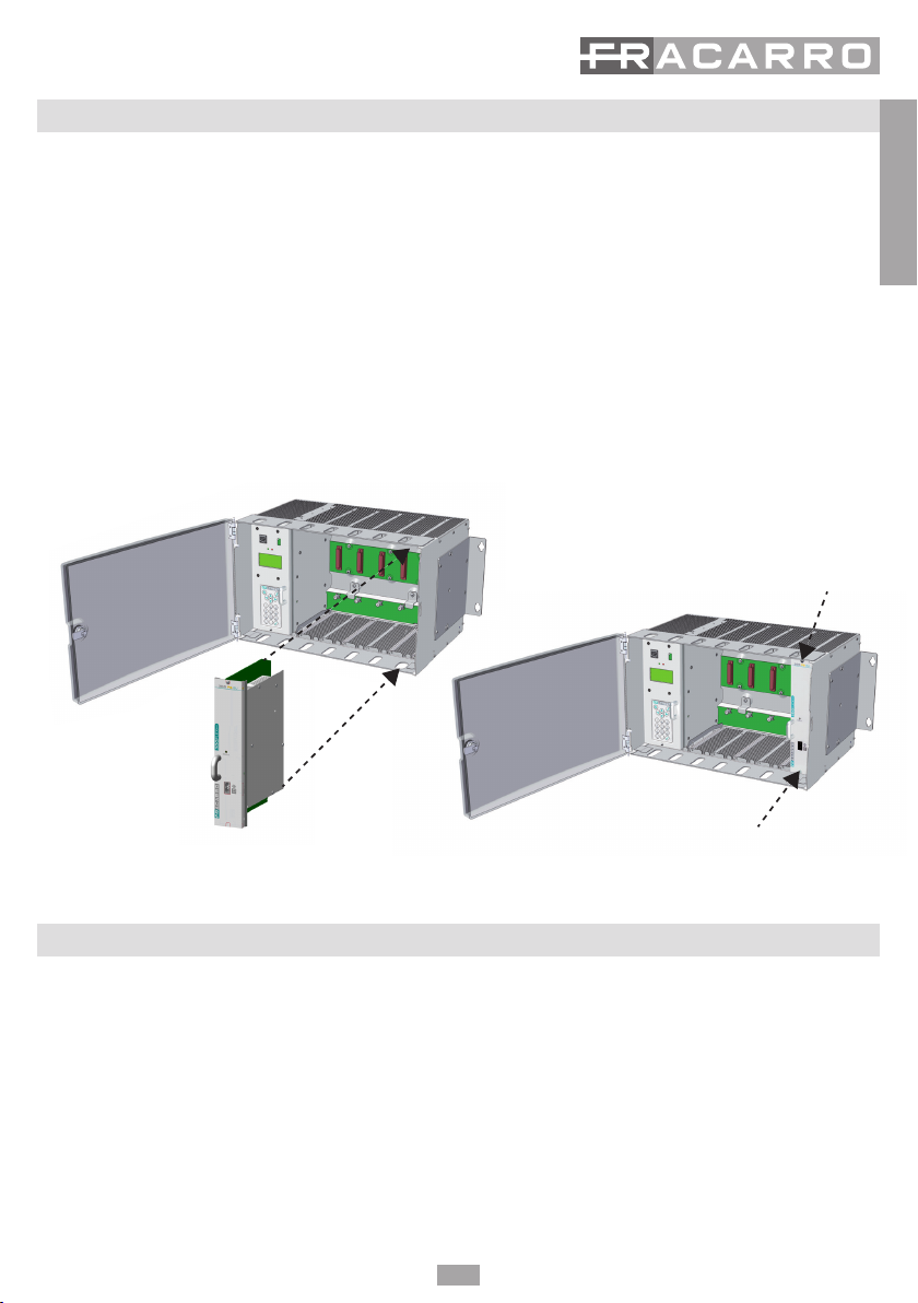
• Il prodotto deve essere installato nell’ultima posizione del cestello della centrale 3DGFLEX
• Il prodotto non deve essere esposto a gocciolamento o a spruzzi d’acqua e va pertanto installato in un am-
biente asciutto, all’interno di edici.
• Umidità e gocce di condensa potrebbero danneggiare il prodotto. In caso di condensa, prima di utilizzare il
prodotto, attendere che sia completamente asciutto.
• Maneggiare con cura. Urti impropri potrebbero danneggiare il prodotto.
• Lasciare spazio attorno al prodotto per garantire una ventilazione sufciente.
• L’eccessiva temperatura di lavoro e/o un eccessivo riscaldamento possono compromettere il funzionamen-
to e la durata del prodotto.
• Non installare il prodotto sopra o vicino a fonti di calore o in luoghi polverosi o dove potrebbe venire a con-
tatto con sostanze corrosive.
• Attenzione: Per evitare di ferirsi, questo prodotto deve essere installato nel cestello, seguendo le istruzioni di
montaggio riportate nel Capitolo 3.
• Per “APPARECCHIATURE INSTALLATE PERMANENTEMENTE” un dispositivo di sezionamento facilmente
accessibile deve essere incorporato all’sterno dell’apparecchiatura; per “APPARECCHIATURE CON SPINA DI
CORRENTE” la presa deve essere installata vicino all’apparecchiatura ed essere facilmente accessibile.
• ll cestello sul quale sarà installato il prodotto deve essere collegato, direttamente o attraverso il rack, all’elet-
trodo di terra dell’impianto d’antenna conformemente alla norma EN 60728-11.
• La vite predisposta per tale scopo è contrassegnata con il simbolo
• Si raccomanda di attenersi alle disposizioni della norma EN 60728-11 e di non collegare tale vite alla terra di
protezione della rete elettrica di alimentazione.
Simbolo di classe II Simbolo di terra dell’impianto d’antenna
AVVERTENZE GENERALI
In caso di guasto non tentate di riparare il prodotto altrimenti la garanzia non sarà più valida.
Le informazioni riportate in questo manuale sono state compilate con cura, tuttavia Fracarro Radioindustrie S.r.l. si riserva il
diritto di apportare in ogni momento e senza preavviso, miglioramenti e/o modiche ai prodotti descritti nel presente manuale.
Consultare il sitowww.fracarro.com per le condizioni di assistenza e garanzia.
2. INTRODUZIONE
La famiglia 3DGFlex è una centrale di testa modulare dotata di un cabinet (3DG-BOX cod. 283156) che consente
l’alloggio di sei moduli ed una Control Unit che permette l’utilizzo e la programmazione della centrale.
La Control Unit consente di:
• Alimentare no a 6 moduli
• Programmare la centrale attraverso la tastiera ed il display di bordo oppure tramite un’interfaccia Web (PC)
da rete locale o da rete remota
• Monitorare in tempo reale lo stato della centrale ed inviare segnalazioni via e-mail
• Importare o esportare la congurazione della centrale via USB
1. AVVERTENZE PER LA SICUREZZA

4
Italiano
3DG-PS-BU è un modulo di alimentazione di Backup alloggiabile solo nell’ultimo slot del cestello della
centrale 3DG FLEX. Tale modulo lavora in parallelo con l’alimentazione della Control Unit e consente , in
caso di guasto all’alimentatore della Control Unit, di mantenere alimentata ed operativa tutta la centrale,
garantendone la continuità di servizio. Il modulo è dotato di un ingresso di rete elettrica indipendente da
quello della Control Unit, e di un led multifunzione che ne indica lo stato di funzionamento.
Il modulo è compatibile solo con le centrali 3DG FLEX che montano la Control Unit EVO, la sua
installazione in centrali con Control Unit antecedenti potrebbe comprometterne il funzionamento.
3.1 Descrizione Scheda
3.2 Descrizione Led LED STATO INGRESSI
LED INDICAZIONE
Spento Assenza di alimentazione sia su CU che su modulo
Verde Il modulo sta funzionando correttamente
Rosso Il modulo è scollegato dalla rete elettrica/ è guasto
3. DESCRIZIONE DEL PRODOTTO

5
Italiano
4. INSTALLAZIONE DEL PRODOTTO
4.1 CONTENUTO DELLA CONFEZIONE
La confezione contiene i seguenti articoli:
• Modulo 3DG-PS-BU
• Avvertenze di sicurezza e Istruzioni per l’installazione del prodotto.
4.2 MONTAGGIO DEL MODULO
SI RICORDA CHE IL MODULO 3DG-PS-BU DEVE OBBLIGATORIAMENTE ESSERE INSERITO NELL’ULTIMO
SLOT DELLA CENTRALE.
1-Scollegare l’alimentazione della centrale (se collegata).
2-Montare il modulo sull’ultimo slot della centrale, ssandolo con le viti in dotazione.
3-Alimentare la centrale ed il modulo con gli appositi cavi di alimentazione.
N.B.: Per garantire il corretto funzionamento dei moduli e per garantire un'adeguata schermatura contro le interferenze radio,
è necessario fissare il modulo con le viti fornite.
Vite Inferiore
Vite superiore
Inserire con attenzione nella guida dell'alloggiamento
5. ISTRUZIONI PER L’UTILIZZO
Una volta alimentata la centrale ed il modulo si deve attendere l’inizializzazione di entrambe (compare il logo
Fracarro sul display della Control Unit) , a questo punto è possibile accedere al menu della centrale:
● accedere al menu premere il tasto “√ ”, digitare il codice utente (default 1234) e confermare con “√”.
● La centrale eseguirà uno scan per trovare i moduli presenti, riportando nella posizione 6 il modulo 3DG-PS-BU.
● Vericare lo stato del modulo in base al colore del led presente sul frontale del modulo stesso,come da Tabella 1.

6
Italiano
6. INTERFACCIA WEB
La centrale 3DGFLEX può essere programmata facilmente attraverso un’interfaccia WEB che è possibile
accedervi attraverso il browser di un PC. E’ fondamentale non congurare gli eventuali 6 moduli utilizzando
6 diverse schede di navigazione contemporaneamente in quanto la CU non risponde alla richiesta multipla dei
parametri da web, anzi prende come prioritaria e unica funzionante l’ultima nestra aperta. IMPORTANTE: per
riuscire ad accedere alla programmazione tramite la web interface, è necessario che la C.U. si trovi all’esterno
del menù a pannello (logo 3DGex Fracarro visualizzato a display). NOTA: l’interfaccia WEB potrebbe subire
variazioni in funzione della versione Firmware caricata nel modulo.
6.1 CONNESSIONE WEB INTERFACE
La procedura da seguire è la seguente:
1. Collegare il PC alla centrale per mezzo di un cavo RJ-45 di CAT-5E oppure passando attraverso uno switch.
2. Modicare l’indirizzo IP del PC o della centrale, per renderli compatibili nella stessa sottorete (così che possano
comunicare)
Ad esempio:
a. Parametri impostati nelle proprietà della scheda di rete del PC
IP: 192.168.0.3
SUBNET MASK: 255.255.255.0
GATEWAY: 192.168.0.1
b. Parametri da impostare nella control unit
IP: 192.168.0.2
SUBNET MASK: 255.255.255.0
GATEWAY: 192.168.0.1
3. Avviare il browser internet (browser consigliati: Google Chrome, Mozilla);
4. Digitare nella barra degli indirizzi l’indirizzo IP associato alla 3DGex; e verrà visualizzata la schermata iniziale
(g. 1). Inserire nome utente e password per accedere all’home page della web interface.
di Default
Nome Utente: admin
Password: 1234
6.2 MENU HOME
Nel menù “Home” della 3DGFLEX è visibile lo stato generale della centrale.
Selezionare la lingua per i menù dell’interfaccia web tra Inglese, Tedesco, Italiano e Francese.
Il primo modulo presente è la control unit 3DG-CU, (far riferimento al manuale della C.U. per l’impostazione dei
parametri della stessa tra i quali i parametri di rete) gli altri moduli dalla posizione 1 alla 6 possono essere presenti
o non presenti < >.
Se il modulo è presente in questa nestra possiamo visualizzare il suo stato.

7
Italiano
Potranno presentarsi 3 casi con relative visualizzazioni:
1-Sia il modulo 3DG-PS-BU che l’alimentatore della Control Unit sono collegati alla rete elettrica e funzionanti;
la visualizzazione nella schermata HOME sarà quella riportata in gura 2.
Fig. 2
2-L’alimentatore della Control Unit non è collegato alla rete elettrica od è difettoso e non eroga tensioni;
Il modulo 3DG-CU verrà evidenziato con un triangolo rosso di anomalia, il modulo 3DG-PS-BU avrà il segno di
spunta verde, come in Figura 3.
Fig. 3

8
Italiano
3-Il modulo 3DG-PS-BU non è collegato alla rete elettrica od è difettoso e non eroga tensioni;
Il modulo 3DG-PS-BU verrà evidenziato con un triangolo rosso di anomalia, il modulo 3DG-CU avrà il segno di
spunta verde, come in Figura 4.
Fig. 4
7. MONITORAGGIO
La centrale consente di monitorare degli eventi ed anomalie che si potrebbero presentare nel tempo (ad esem-
pio mancanza rete elettrica ecc ecc).
E’ possibile creare uno storico, un le esportabile oppure l’invio di mail riportanti una serie di anomalie od eventi.
Per abilitare questa funzione è necessario entrare nella programmazione della control unit da “Home”, poi
“Monitoraggio” e “Congurazione”, apparirà la schermata di gura 5.
Dal menu di congurazione Stato monitoraggio è possibile impostare quali eventi monitorare, selezionando la
voce malfunzionamento PSU e cliccandoci sopra con il tasto destro del mouse comparirà il menu di gura 6,
in cui è possibile:
-Abilitare il monitoraggio sul funzionamento dell’alimentatore ;
-Abilitare il salvataggio degli eventi nello storico memorizzato dalla Control Unit;
-Abilitare l’invio di una e-mail in caso di malfunzionamento;
-Selezionare il numero di eventi dopo il quale viene memorizzata l’anomalia ed inviata la mail
-Impostare il testo da memorizzare ed inviare in caso si presenti l’anomalia.

9
Italiano
7. SPECIFICHE TECNICHE
Temperatura operativa °C -5 - +45
Tensione di alimentazione V~ 230
Frequenza di alimentazione Hz 50-60
Classe di isolamento Classe II
Massimo consumo W 135
Dimensioni mm 246 x 52 x 209

English
10
Contents
SAFETY WARNINGS 11
INTRODUCTION 11
PRODUCT DESCRIPTION 12
3.1 Module description 12
3.2 LED description 12
INSTALLING THE PRODUCT 13
4.1 Contents of the packaging 13
4.2 Module mounting 13
OPERATING INSTRUCTIONS 13
WEB INTERFACE 14
6.1 WEB INTERFACE CONNECTION 14
6.2 HOME Menu 14
MONITORING 16
TECHNICAL SPECIFICATIONS 17
COMPLIANCE TO EUROPEAN DIRECTIVES 36

English
11
The product can only be installed by qualied personnel in compliance with local safety laws and regulations. Fracarro
Radioindustrie is free from all civil and criminal responsibility due to breaches of current legislation derived from the improper
use of the product by the installer, user or third parties.
The product must be used in full compliance with the instructions given in this manual, in order to protect the operator against
all possible injury and the product from being damaged.
Don’t open the product case: components under dangerous voltage may be accessible when the case is opened.
SAFETY WARNINGS
• The product must be installed in the last position of the 3DG-BOX cabinet.
• The product must not be exposed to water drips and must be installed indoors inside in dry places.
• Damp and condensation drops could damage the product. Consequently, always wait for the product to be
perfectly dry before use.
• Handle with care. Knocks could damage the product.
• Leave plenty of space around the product to ensure sufcient ventilation.
• High temperatures or overheating could compromise the product functions and life.
• Do not install the product above or close to sources of heat, in dusty atmospheres or when it could be
exposed to corrosive substances.
• To prevent injury, the product should be installed in the cabinet, following the assembly instructions given
in Chapter 3.
• The “PERMANENTLY INSTALLED UNITS” must be equipped with an easily accessible power disconnecting
switch easy to reach. “UNITS WITH A POWER PLUG,” the outlet must be installed near the unit and easy to reach.
• The cabinet where the product is installed must be connected either directly or by means of the rack to the
earth electrode of the antenna installation according to the EN 60728-11 regulation.
• The earth screw is indicated with the symbol
• It is important to observe the provisions of the EN60728-11 standard and not to connect this screw (clamp)
(product) to the power supply earth line.
Class II symbol with earth connection Earth screw symbol of the antenna installation
GENERAL PRECAUTIONS
In case of a malfunction, do not attempt to repair the product because this would invalidate the guarantee.
The information given in this manual has been carefully prepared, however Fracarro Radioindustrie S.r.l. reserves
the right at any time, and without prior notice, to make any improvements or changes to the product described
in the manual. Consult the website of www.fracarro.com for the terms regarding assistance and the guarantee.
2. INTRODUCTION
The 3DGFlex family is a modular head unit equipped with a cabinet (3DG-BOX code 283156) that can house six
modules and a Control Unit that permits the use and programming of the Central Processing Unit.
The Control Unit can:
• Supply power to up to 6 modules
• Program the Central Processing Unit through the incorporated keypad and display or via a Web interface
(PC) on a local or remote network
• Perform real-time monitoring of the Central Processing Unit status and send email alerts (Controller Host)
• Import or export the Central Processing Unit conguration by a USB
1. SAFETY WARNINGS

English
12
3DG-PS-BU is a backup module which can only be installed in the last position of the 3DG-BOX
cabinet. This module works parallelly with the power of the Control Unit and it allows, in the event of
a failure of the Control Unit’s power supply, to keep the entire power unit powered and operational thus
guaranteeing its service. The module is equipped with an electrical input independent of the Control Unit
and with a multifunctional LED that shows its operating status.
The module is only compatible with the 3DG FLEX control units that mount the Control Unit EVO; its
installation in units with previous Control Units could compromise its operation.
3.1 Chart description
3.2 LED description INPUT LED STATUS
LED INDICATION
Off No power on both the CU and the module
Green The module is operating properly
Red The module is disconnected from the power supply/is failed
3. PRODUCT DESCRIPTION

English
13
4. 1. INSTALLING THE PRODUCT
4.1 CONTENT OF THE PACKAGE
The following materials are inside the box:
• 3DG-PS-BU module
• Power supply cord
• Safety and installation instructions
4.2 MODULE MOUNTING
PLEASE REMEMBER THAT THE 3DG-PS-BU MODULE MUST BE INSERTED IN THE LAST SLOT OF THE
CONTROL UNIT.
1-Cut off the control unit power (if connected).
2-Mount the module in the last slot of the control unit and x it by using the supplied screws.
3-Charge the control unit and the module by using the proper power cables
.
5. OPERATING INSTRUCTIONS
After the control unit and the module are powered, wait for the initialization of both of them (the logo Fracarro
appears on the display of the Control Unit); now you can enter the control unit menu:
●
access the menu, press the “√” button, enter your user code (default code1234) and then conrm by pressing “√”.
●
The control unit will scan all the modules and return to the 3DG-PS-BU module in position 6.
●
Check the status of the module according to the colour of the LED on the module front; see Table 1.

English
14
6. WEB INTERFACE
The 3DGFLEX control unit can be programmed easily by a WEB interface where you can enter with a PC browser.
It is essential not to congure any 6 modules using 6 different navigation cards simultaneously since the Control
Unit does not answer to multiple parameter requests from the web but rather it considers the last window open
as a priority and the only one working.
IMPORTANT: to enter programming by web interface, the Control Unit must be outside the displayed menu (logo
3DGex Fracarro displayed).
NOTE: The Web interface can have some changes according to the rmware version loaded in the module.
6.1 WEB INTERFACE CONNECTION
The following is the proper procedure:
1. Connect the PC to the control unit with a RJ-45 di CAT-5E cable or use a switch.
2. Modify the IP address of the PC or the control unit and make them compatible in the same subnetwork
(so that they can communicate)
For example:
a. The parameters set in the network card of the PC:
IP: 192.168.0.3
SUBNET MASK: 255.255.255.0
GATEWAY: 192.168.0.1
b. Parameters to set in the control unit
IP: 192.168.0.2
SUBNET MASK: 255.255.255.0
GATEWAY: 192.168.0.1
3. Start the Internet browser (recommended browsers: Google Chrome, Mozilla);
4. Enter the IP address associated to the 3DGex in the address bar and the initial screen will be displayed
(g. 1). Enter the username and password to enter the web interface home page.
By Default
Username: admin
Password: 1234
6.2 HOME MENU
The general status of the control unit is given by the 3DGFLEX Home menu.
Select the language for the web interface menus (i.e. English, German, Italian and French are available).
The rst module is the 3DG-CU control unit, (please refer to the Control Unit manual for setting the unit’s
parameters such as the network parameters), the other modules from position 1 to position 6 can be present
or not < >.
If the module is present, this window displays its status.

English
15
Three cases can occur:
1- Both the 3DG-PS-BU module and the Control Unit’s feeder are connected to the power network and working;
the display in the HOME window will be as given in gure 2.
Fig. 2
2-The control Unit’s feeder is not connected to the electrical network or is not working properly and does not
supply power;
The 3DG-CU module will be shown with a red triangle, which means an anomaly is occurring; the 3DG-PS-BU
module will have a green tick as given in Figure 3.
Fig. 3

English
16
3-The 3DG-PS-BU module is not connected to the electrical network or is not working properly and is not
supplying power;
The 3DG-PS-BU module will be shown with a red triangle, which means an anomaly is occurring, the 3DG-CU
module will have a green tick as given in Figure 4.
Fig. 4
7. MONITORING
The control unit allows you to monitor the events and the failures that can occur (for example, power supply
failure, etc.).
An exportable le of the historic events can be created or emails can be sent to report failures or events.
To enable this function, enter programming of the control unit from “Home”, then “Monitoring” and
“Conguration”; the window given in gure 5 will appear.
From the conguration menu and Monitoring Status, you can set which events should be monitored. Select the
PSU malfunctioning and right click it with the mouse; the menu given in Figure 6 will appear. From this menu,
you can do the following:
- Enable monitoring of the power supply operation;
- enable the saving of events in the Control Unit historic;
- enable email notication in the event of a failure;
- Select the number of events after which the failure is memorized and the email is sent
- Set the text to be memorized and sent in the event of a failure.

English
17
7. TECHNICAL SPECIFICATIONS
Operating temperatures °C -5 - +45
Voltage V~ 230
Power supply frequency Hz 50-60
Insulation class: Class II
Maximum consumption W 135
Dimensions mm 246x52x209

Français
18
TABLE DES MATIÈRES
CONSIGNES DE SÉCURITÉ 19
INTRODUCTION 19
DESCRIPTION DU PRODUIT 20
3.2 description de la che 20
3.2 Description LED 20
INSTALLATION DU PRODUIT 21
4.1 description du module 21
4.2 Montage du module 21
INSTRUCTIONS D’UTILISATION 21
INTERFACE WEB 22
6.1 Connexion à l’INTERFACE WEB 22
6.2 Menu ACCUEIL 22
MONITORAGE 24
SPÉCIFICATION TECHNIQUES 25
CONFORMITÉ AUX DIRECTIVES EUROPÉENNES 36

Français
19
L’installation du produit doit être effectuée par du personnel qualié conformément aux lois et aux normes locales sur la sécu-
rité. Par conséquent, Fracarro Radioindustrie décline toute responsabilité civile ou pénale dérivant de violations des normes
juridiques en vigueur et de l’utilisation incorrecte du produit de la part de l’installateur, de l’utilisateur ou de tiers.
Le produit doit être installé en suivant les indications fournies, an de préserver l’opérateur d’éventuels accidents et le produit
d’éventuels endommagements. Ne pas ôter le couvercle du produit ; des pièces sous tension dangereuse peuvent être acces-
sibles lors de l’ouverture de la coque.
Avertissements concernant l’installation
• 1Le produit doit être installé dans la dernière position dans l’armoire de la station 3DG FLEX
• Le produit ne doit pas être exposé à l’égouttement ou aux éclaboussures d’eau et il doit donc être installé
dans un endroit sec, à l’intérieur.
• L’humidité et les gouttes de condensation, pourraient endommager l’appareil. En cas de condensation, at-
tendre que le produit soit complètement sec avant de l’utiliser.
• Manier avec soin. Les chocs pourraient endommager le produit.
• Laisser de l’espace autour du produit pour garantir une ventilation sufsante.
La température excessive de fonctionnement et/ou un réchauffement excessif peuvent nuire au fonction-
nement et à la durée du produit.
• Ne pas installer le produit sur ou près des sources de chaleur, dans des endroits très poussiéreux ou en
contact avec des substances corrosives.
• Pour éviter de se blesser, ce produit doit être installé dans l’armoire en suivant les instructions de montage
décrites au Chapitre 3.
• Pour des « APPAREILS INSTALLÉS DE FAÇON PERMANENTE », un dispositif de sectionnement facilement ac-
cessible doit être incorporé à l’extérieur de l’appareil ; pour des « APPAREILS AVEC UNE PRISE DE COURANT
», la prise doit être installée à proximité de l’appareil et être facilement accessible.
• L’armoire dans laquelle le produit est installé doit être raccordée, directement ou à travers le rack, à l’élec-
trode de mise à la terre de l’antenne conformément à la norme EN 60728-11.
• La vis prévue à cet effet est marquée du symbole ….
• Il est conseillé de respecter les dispositions de la norme EN 60728-11 et de ne pas relier cette vis à la mise à
la terre de protection du secteur.
Symbole de classe II avec un branchement à la mise à la terre fonctionnelle
Symbole de mise à la terre de l’antenne
Avertissements généraux
En cas de panne, ne pas tenter de réparer le produit, sans quoi la garantie ne sera plus valable. Les informations indiquées dans
ce mode d’emploi ont été renseignées soigneusement ; toutefois, Fracarro Radioindustrie S.r.l. se réserve le droit d’améliorer et/
ou de modier à tout moment et sans préavis les produits décrits dans ce mode d’emploi. Consulter le site www.fracarro.com
pour connaître les conditions d’assistance et de garantie.
2. INTRODUCTION
La famille 3DGFlex est une station de tête modulaire dotée d’un boîtier (3DG-BOX cod. 283156) qui permet de
loger six modules et une Unité de Contrôle permettant d’utiliser et de programmer la station.
L’Unité de Contrôle permet de :
• Alimenter jusqu’à 6 modules
• Programmer la station depuis le clavier et l’écran de bord ou bien à l’aide d’une interface Web (PC) depuis
un réseau local ou un réseau à distance.
Suivre l’état de la station en temps réel et envoyer des rapports par email (Controller Host)
• Importer ou exporter la conguration de la station via USB
1. CONSIGNES DE SÉCURITÉ

Français
20
3DG-BP-BU est un module d’alimentation de Secours qui ne peut être logé que dans le dernier port de l’armoire
de la station 3DG FLEX. Ce module fonctionne en parallèle avec l’alimentation de l’Unité de Contrôle et il permet,
en cas de panne de l’alimentation de l’Unité de Contrôle, de maintenir toute la station alimentée et opérationnelle,
garantissant ainsi la continuité du service. Le module est doté d’une entrée secteur indépendante de celle de
l’Unité de Contrôle et d’une led multifonctions qui indique l’état de fonctionnement.
Le module n’est compatible qu’avec les stations 3DG FLEX dotées de l’Unité de Contrôle EVO. S’il est
installé dans des stations avec des Unités de Contrôle précédentes, son fonctionnement pourrait être
compromis.
3.1Descriptiondelache
3.2 Description LED LED STATO INGRESSI
LED Indication
Éteinte Absence d’alimentation sur l’Unité de Contrôle et sur le module
Verte Le module fonctionne correctement
Rouge Le module est débranché du secteur / est en panne
3. DESCRIPTION DU PRODUIT
Table of contents
Languages:
Other Fracarro Control Unit manuals
Popular Control Unit manuals by other brands

Siemens
Siemens Desigo PXC4.E16 manual

Chore-Time
Chore-Time Tronics 3 manual

Viessmann
Viessmann Vivotronic 050 HK1S Installation and service instructions

Flann Microwave
Flann Microwave 624 Instrument manual

EOS
EOS Farblichtmodul Assembly instruction

aci
aci ACCESS series Installation & operation instructions