Elo TouchSystems ELO E00X User manual

RS-232 Miniature Converter to Current Loop
ELO E00X
Operation manual

ELOE00XZKE001
2
1.0 Introduction ............................................................................. 3
1.1 Use of the converter ................................................................. 3
2.0 Operation principles ................................................................ 3
3.0 Installation ............................................................................... 3
3.1 RS-232 interface connection ................................................... 3
3.2 Two Modems interconnection ................................................. 4
3.3 Power Supply Connection ....................................................... 5
4.0 Specifications ........................................................................... 5
4.1 Parameters ............................................................................... 5
4.2 Other......................................................................................... 6
5.0 Testing ...................................................................................... 6
5.1 Auto-test ................................................................................... 6
6.0 Troubleshooting ....................................................................... 7
7.0 Ordering Information.............................................................. 7

ELOE00XZKE001
3
1.0 Introduction
RS-232 is the interface with asymmetric signals. Maximum load capacity can be
2500pF and equates to c.50m typical twisted-pair cable.
The asymmetric signals are not ideal to eliminate the influence of zero potential
differences of terminal equipments (TE and/or DTE). The TE and neutral potentials
have to be the same hence the RS-232 interface is intended to the point-to-point
connection for 15m distance.
The load impedance is to be 3-7 kilo-ohm that allows disturbing pulses to induce
into the cable even from the soft supplies.
1.1 Use of the converter
Current loop interface is resistant to electromagnetic interference but not to
atmospheric electricity influences!
The current loop enables to span the metallic link of the resistance up to 500 Ohm
using the power supply of 12 V.
2.0 Operation principles
E00X converts TxD signal into the transmitting cable pair of the current loop and
the signal from the receiving pair into the RxD thus the full duplex connection is
carried out. In the idle mode the 20mA current flows through each current loop.
The maximum transmission rate is 115 200 bps. Control signals are not transmitted.
3.0 Installation
There are two different problems of installation to discuss: the converter and the
TE connection via the RS-232 interface and two modems interconnection.
3.1 RS-232 interface connection
The DB9F (Female) connector is used to the converter connection. The connector
is connected as the DCE (to the end device connector, the converter can be
connected directly or via the cable 1:1). Signals assignment to the contacts and
signals´ direction is in the following table:

ELOE00XZKE001
4
abbrev trans.direction
Signal name DB9 Female DTE converter
(DCE)
Signal Ground SG 5 -- --
Transmitted Data TxD 3 output input
Received Data RxD 2 input output
Request To Send RTS 7 output input
Clear To Send CTS 8 input output
Data Set Ready DSR 6 input output
Data Terminal Ready DTR 4 output input
Data Carrier Detect DCD 1 input output
3.2 Two Modems interconnection
For the duplex operation, two current loops - transmitting and receiving - are used
to interconnect the converters. To each loop, the twisted pair should be applied to
limit the radiation and particularly the disturbance from outside. Each loop
connects one transmitter to one receiver and has to contain a power supply. The
transmitter or receiver supplies this power most often, it is so-called active
transmitter or receiver whereas the passive receiver is a consumer and the passive
transmitter is a current switch that supplies the active equivalent.
The converters´ operation mode implies the way of their connection. There are
three modes selected via the contacts on the DB9M link connector:
1) The active transmitter and receiver
2) The passive transmitter and receiver
3) The active transmitter and passive receiver

ELOE00XZKE001
5
3.3 Power Supply Connection
The converter contains two isolated parts that have to be supplied from two
supplies isolated from each other. The RS-232 interface circuit is supplied from the
TE signals. The TE has to supply at least one of TxD, RTS and DTR signals. The
power take-off does not exceed c.3mA.
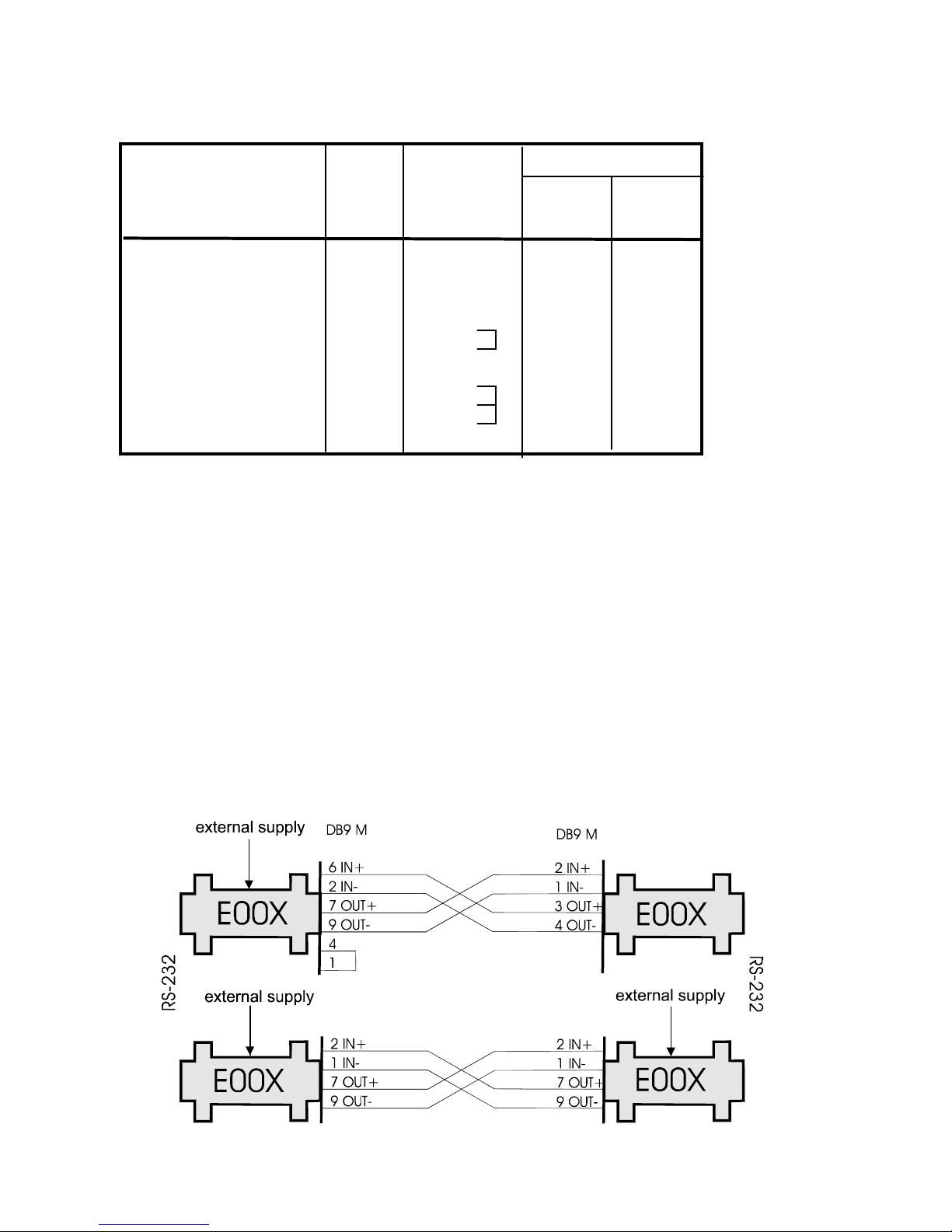
The current loop circuits need the power supply as described in 3.2 chapter. If the
converter operates in the passive transmitter and receiver mode it works with the
current supplied via the opposite converter and does not need the external power
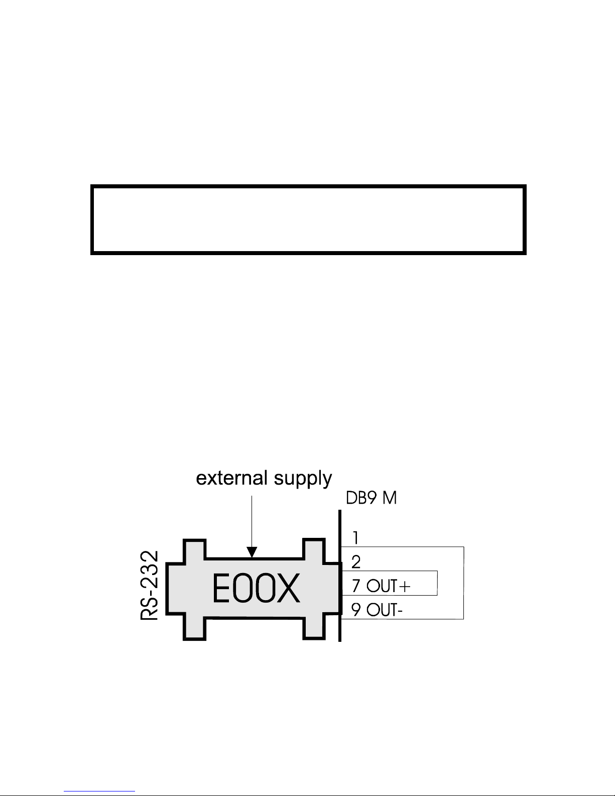
supply. When in the active receiver or transmitter mode, the power supply to the
loops is needed. The supply is connected via the DC connector on the converter
case or via 8 (positive) or 4 (negative) contacts on the current loop connector.
The power supply of 12V/100mA is used most often, E0Q4 type. The power supply
voltage may be of maximum 24V for one supplied current loop thus up to 50mA.
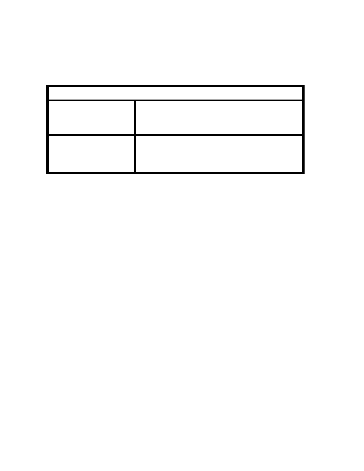
4.0 Specifications
4.1 Parameters
RS-232 interface DCE
RS-232 connector DB9F
Current loop interface transmitter and receiver
active / passive
Current loop connector DB9M
Loop current in idle mode 20mA
Isolation between interfaces 1 kV
Transmitted signals TxD and RxD, full duplex
Control signals are not transmitted, local jumpers
RTS-CTS, DTR-DSR-DCD
RS-232 connector DB9F, DCE
Transmission mode half-duplex
Power supply external DC supply 6V/200mA
Maximum range of the link with
parameters: 200Ohm, 50nF / 1km 1000m
Maximum data rate 115 200 bps
Minimum data rate 50 bps
Supply typ. 12 V, max. 24 V / 50 mA
Dimension: Width x Length x Height 34 x 64 x 17 mm
Weight 25 g

ELOE00XZKE001
6
Stocking temoerature - 10 o to +55 o C
Working temperature + 0oto +50oC
Humidity 0 – 85% (non-condensing)
4.2 Other
!!! Caution !!!
The converter use is not allowed in lines exposed to the atmospheric
electricity effects.
5.0 Testing
If interconnected properly, both diodes light up on each modem. Any simple
communication test can be used (terminal emulator, …).
5.1 Auto-test
You can test either single converter or connected to the terminal equipment with
the external supply of 12 – 24 V. The DB9M connector contacts are interconnected
via two jumpers: 7-2 and 9-1.
Both diodes must be alight. The transmitted sign has to appear in the receiver
(ECHO).

ELOE00XZKE001
7
6.0 Troubleshooting
Symptom Action
Converter does not work Check if both diodes light.
after installation Check the power supply.
Check RS-232 connection.
Connection in normal Check the power supply.
operation quit working Check the cable connection.
Use auto-test and find out if the converter is OK.
7.0 Ordering Information
Supply code is ELO E00X.

ELOE00XZKE001
8
Table of contents
Other Elo TouchSystems Media Converter manuals