Elo TouchSystems E171 User manual

RS – 485 to Multimode Fibre Optic Converter
ELO E171
Operation manual

ELOE171ZKE001
2
1.0 Introduction ....................................................................................3
1.1 Use of the converter ........................................................................3
2.0 Operation principles .......................................................................3
3.0 Installation ......................................................................................3
3.1 RS-485 Interface Connection.........................................................4
3.2 Fibre Link Connection ...................................................................5
3.3 Power Connection...........................................................................5
4.0 Specification....................................................................................5
4.1 Parameters ......................................................................................5
4.2 Other................................................................................................6
5.0 Testing .............................................................................................6
6.0 Troubleshooting ..............................................................................6
7.0 Ordering Information.....................................................................6

ELOE171ZKE001
3
1.0 Introduction
Fiber Optic (SINGLE MODE and/or MULTI MODE) has been used for signal
transmission in automation for communication more and more often.
The main advantage of Fiber Optic is its immunity to electromagnetic interference,
slight radiation and high transmission capacity
1.1 Use of the converter
Conversion of metallic media to more expensive fiber optic is mainly suitable:
1] in the environment of high interference level,
2] if the higher isolation is required, (switching stations, transformers),
3] if the metallic line can not be used because of EMI ,
4] if the higher transport security and safety is necessary,
5] if isolation via the optocouplers is not suitable for
different reasons
These problems can be solved if the converter ELO E 171 (MULTI MODE) is applied.
2.0 Operation principles
ELO E171 transfers signal received from RS-485 interface to transmitting fiber of the
optic cable and the signal from receiving fiber is transmitted to RS-485.
Besides the signal transfer, the converter matches the full duplex fiber to the half duplex
RS-485 (data-flow direction switching).
Its independent operation is based on the set data rate (1200 to 115200 bps) and data
format which must be asynchronous of 10 and/or 11bits (start bit, 8 to 9 information
bits, stop bit). The switching speed is sufficient to use the converter in data transmission
network organized as MASTER-SLAVE and MULTI MASTER.
The converter also corrects bits width distortion which could occur during transmission.
For fiber optic connection optical connector ST is used as standard.
3.0 Installation
There are two different problems of installation to discuss:
RS-485 link and fiber optic link connection and setting
characteristics of the converter.
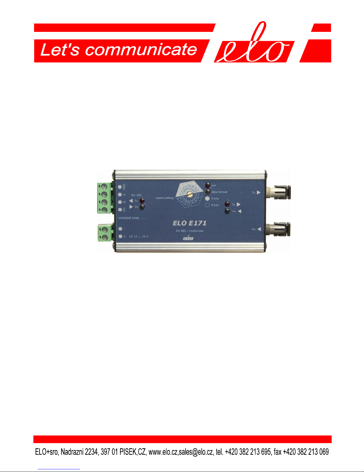
The converter needs data range and data format setting
(asynchronous word length). There is the rotating switch on
the top converter case (see the figure). Switch slot points to
the light and dark scale sector at the same time. If the LED “data format” is alight, 9 bits
data format is set (e.g.8 data bits and a parity bit), if it is not alight 8 bits format is
1.2
2.4
4.8
9.6
19.2
38.4
57.6
115.2
9 bits
run
data
format
8 bits

ELOE171ZKE001
4
selected (e.g. 8 data bits without parity). 19.2 kbps rate and 9 bits format is set in the
picture. When in operation, received and transmitted data and data flow direction is also
indicated by LED.
3.1 RS-485 Interface Connection
There is the isolation between the RS-485 interface clamp and all the other converter
circuits. The 3kV voltage can be applied for 1 second without a failure. The RS-485
interface signal is placed on A-B clamps. The clamps VCC (+5V) and SG (signal
ground) are used to connect terminators, see the figure.
Both the RS-485 link ends should be
terminated with the 100-120 resistors
(so-called passive terminators), which are
placed between A-B wires. These
terminators are used for the converter
impedance matching, they suppress the
undesirable echo and they influence the
transfer immunity against interference.
Inserting the optical converter into the
metallic link terminates this link right on
the A-B clamps of the converter therefore it
is necessary to connect the passive
converter.
There are also the active terminators beside
the passive ones. Only one active
terminator can be installed to one metallic
section of the link and its role is as follows:
The RS-485 signal is symmetric. The differential receiver interprets the difference UA-
UB. It does not depend on the signal ground potential. The receiver interprets the
obtained signal UA– UB> 200 mV as log. 1 or log. 0.
In addition to these levels the third state can occur, it is so-called IDLE state. No
transmitter is activated, each communicating partner is just listening soUA-UB< 200
mV. The problem is how to interpret the third state in the two-state logic. The active
terminator gives the signal into the IDLE state line and it is interpreted as IDLE in the
two-state logic.

ELOE171ZKE001
5
3.2 Fibre Link Connection
The fibre optic cable is connected through the ST400 connectors. To connect the
ELO E171, the transmitter of the remote converter must be connected to the receiver of
the local ELO E171 and the remote receiver must be connected to the local transmitter
(fibres cross).
Both converters must be set to the right data range and data format. The rotating switch
on the top converter case is used to it.
3.3 Power Connection
The external supply has to have the output voltage of 12-24V and it is connected via
DC+ and DC- clamps. The supply take off is c.200 mA. If the supply is on operation the
indicator RUN switches on.
The converter contains two isolated zones. The RS-485 circuits are separated from the
other ones and supplied via the internal isolated DC/DC converter. If it is necessary to
keep this separation the external power supply must be isolated from the signal grounds
of all RS-485 partners.
4.0 Specification
4.1 Parameters
Transmitted signals differential signal AB
Type and connection of RS-485 connector clamps
Isolation RS-485 galvanic isolation from GND
3 kV/1 sec supply
Transmit mode asynchronous, half-duplex
Fibre optic cable two multimode fibres
cables 50/125 µm (62/125µm)
Optic connectors ST type
Maximum data rate 115 200 bps
Minimum data rate 1200 bps
Supply external DC supply 9-24V/200 mA
Dimension: Length 115 mm
Width 55 mm
Height 24 mm
Weight 137 g

ELOE171ZKE001
6
4.2 Other
Stocking temperature -10° to +55°C
Working temperature +0° to +50°C
Humidity 0 – 85% (non-condensing)
5.0 Testing
In case of proper installation the RUN diode is alight. If 9bit data format is selected the
9 bits indicator must be alight. The TxD and RxD indicators must blink during
transmission.
6.0 Troubleshooting
Symptom Action
ELO 171 does not work Check if the RUN is alight.
after installation Check the power supply.
Check the RS-485 link connection.
Connection in normal Check the power supply
operation quit working Check if the cables are OK..
Turn off and on the power supply
and detect if the converter starts again.
7.0 Ordering Information
Supply code is ELO E171.

ELOE171ZKE001
7
Note

ELOE171ZKE001
8
Table of contents
Other Elo TouchSystems Media Converter manuals