McCrometer ML255 User manual

ML255
ELECTROMAGNETIC
FLOW METER CONVERTER
Important Information:
Converter Model Number: ________________________
Converter Serial Number: _________________________
Meter Serial Number: ____________________________
RETAIN THIS MANUAL - DO NOT DISCARD
Installation, Operation and
Maintenance Manual
30122-46, Rev. 1.2
May 31, 2018

Copyright © 2018 McCrometer, Inc. All printed material should not be changed or altered without permission of McCrometer.
Any published technical data and instructions are subject to change without notice. Contact your McCrometer representative
for current technical data and instructions.
www.mccrometer.com
3255 WEST STETSON AVENUE • HEMET, CALIFORNIA 92545 USA Printed In The U.S.A.
TEL: 951-652-6811 • 800-220-2279 • FAX: 951-652-3078 Lit. # 30122-46, Rev. 1.2 / 5-31-18
Contents
SAFETY.....................................................................................1
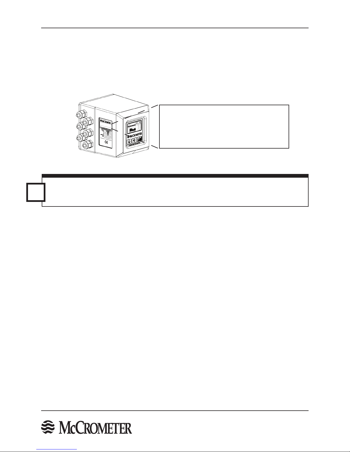
1.0 BATTERY POWERED CONVERTER OVERVIEW ............................................2
1.1 Serial Numbers....................................................................................3
1.2 Compatible Products ..............................................................................3
2.0 CONVERTER INSTALLATION ............................................................4
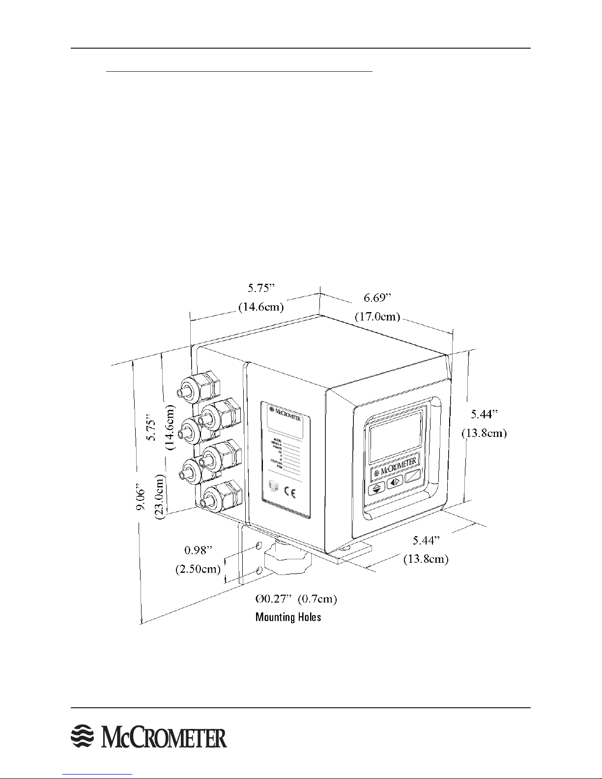
2.1 Mounting The Converter ..........................................................................4
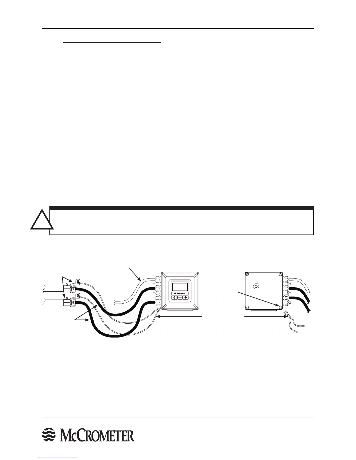
2.2 Installing Cables To Converter And Service Loop ...................................................4
2.3 Pulling Sensor Cable Through Electrical Conduit....................................................5
3.0 BATTERY INSTALLATION AND SYSTEM START-UP ........................................6
3.1 Battery Life .......................................................................................6
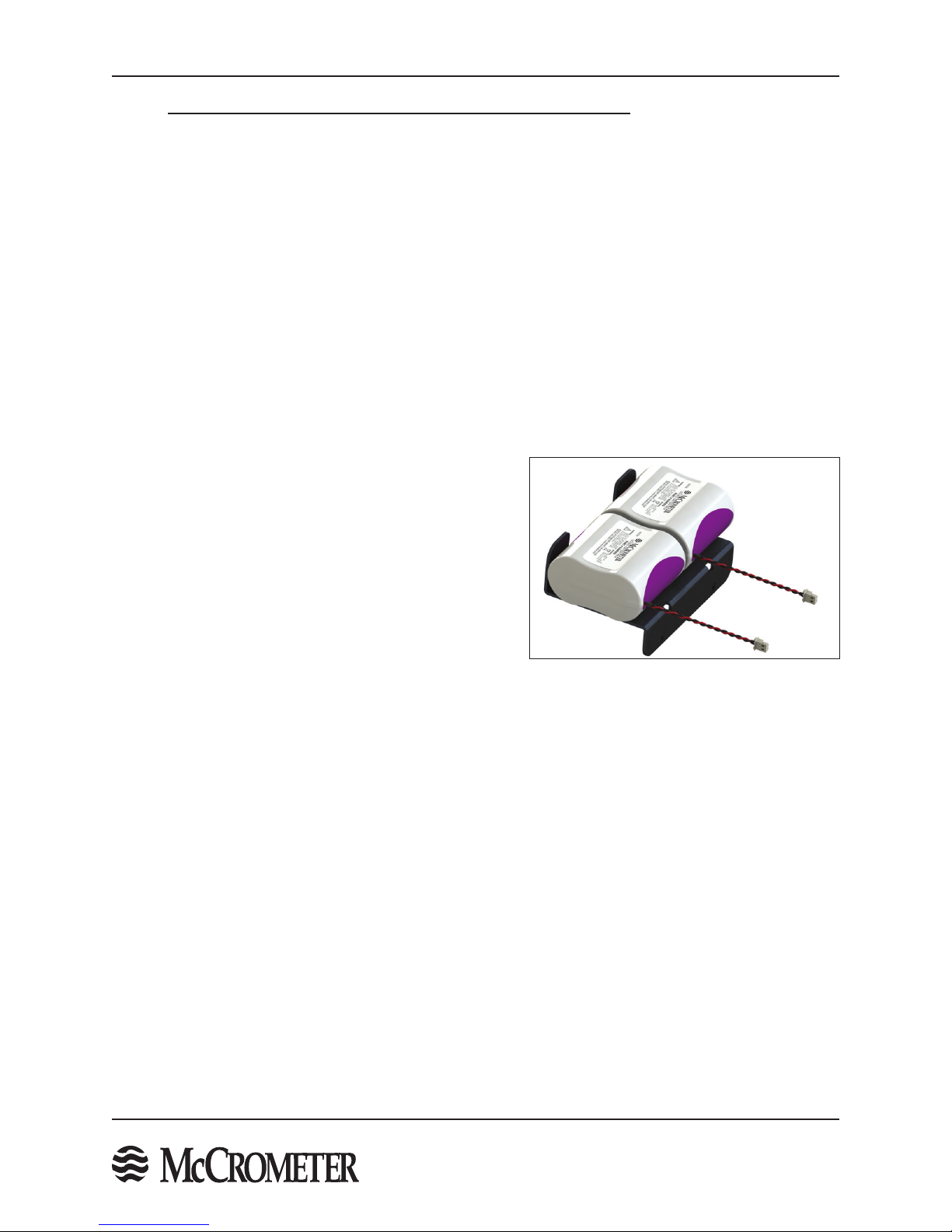
3.2 Installing Batteries and Starting Up ................................................................6
3.3 Setting the Time and Date .........................................................................6
3.4 Replacing Batteries................................................................................7
3.5 Powering-Down and Powering-Up the System .....................................................8
3.6 Power Options ....................................................................................8
3.7 Sampling Frequencies.............................................................................9
4.0 SOLAR PANEL OPTION................................................................10
4.1 Description ......................................................................................10
5.0 ELECTRICAL CABLE CONNECTIONS ....................................................11
5.1 Converter Electrical Cable Connections ...........................................................11
5.2 Terminal Board...................................................................................11
5.3 FPI Mag 395L Forward Only Cable Connections ...................................................13
5.4 SPI Mag 282L Cable Connection ..................................................................14
5.5 Ultra Mag Sensor Cable ..........................................................................15
5.6 Converter Grounding . . . . . . . . . . . . . . . . . . . . . . . . . . . . . . . . . . . . . . . . . . . . . . . . . . . . . . . . . . . . . . . . . . . . . . . . . . . .17
5.7 Opto-Isolated Pulse Output Hook-Up .............................................................18
5.8 Opto-Isolated Pulse Input ........................................................................18
5.9 Converter Power Hook-Up........................................................................19
6.0 CONVERTER START-UP - ALL SENSORS . . . . . . . . . . . . . . . . . . . . . . . . . . . . . . . . . . . . . . . . . . . . . . . . .20
6.1 Menu Navigation.................................................................................20
6.2 Front Panel Visualization Pages ...................................................................21
6.3 Factory Set Key Code .............................................................................22
6.4 Menu Structure ..................................................................................22
7.0 PROGRAMMING EXAMPLE ............................................................25
8.0 MENU 0 - QUICK START ...............................................................26
9.0 MAIN MENU DESCRIPTIONS...........................................................26
9.1 Menu 1 - Sensor .................................................................................26
9.2 Menu 2 - Scales ..................................................................................28
9.3 Menu 3 - Measure ................................................................................31
9.4 Menu 4 - Alarms..................................................................................31
9.5 Menu 5 - Inputs ..................................................................................32
9.6 Menu 6 - Outputs ................................................................................32
9.7 Menu 7 - Communication ........................................................................34
9.8 Menu 8 - Display .................................................................................34
9.9 Menu 9 - Data Logger ............................................................................35
9.10 Menu 10 - Diagnostic.............................................................................35
9.11 Menu 11 - Internal Data ..........................................................................37
10.0 ALARM MESSAGES ...................................................................38
11.0 SPECIFICATIONS .....................................................................42
12.0 TROUBLESHOOTING GUIDE ...........................................................44
APPENDIX 1.0 UNITS OF MEASURE ..........................................................45
APPENDIX 2.0 CONVERSION TABLES.........................................................46
WARRANTY STATEMENT ....................................................................47

SAFETY
Copyright © 2018 McCrometer, Inc. All printed material should not be changed or altered without permission of McCrometer.
Any published technical data and instructions are subject to change without notice. Contact your McCrometer representative
for current technical data and instructions.
www.mccrometer.com
3255 WEST STETSON AVENUE • HEMET, CALIFORNIA 92545 USA Printed In The U.S.A.
TEL: 951-652-6811 • 800-220-2279 • FAX: 951-652-3078 Lit. # 30122-46 Rev. 1.2 / 5-31-18
1
Safety Warnings
When installing, operating, and maintaining McCrometer equipment where hazards may be present, you must
protect yourself by wearing Personal Protective Equipment (PPE) and be trained to enter conned spaces.
Examples of conned spaces are manholes, pumping stations, pipelines, pits, septic tanks, sewage digesters,
vaults, degreasers, storage tanks, boilers, and furnaces.
SAFETY
Safety Symbols And Warnings
Throughout this manual are safety warning and caution information boxes. Each warning and caution box will be
identied by a large symbol indicating the type of information contained in the box. The symbols are explained
below:
!
i
This symbol indicates important safety information. Failure to follow the instructions can
result in serious injury or death.
This symbol indicates important information. Failure to follow the instructions can result in
permanent damage to the meter or installation site.
WARNING!
Pressurized pipes should only be hot tapped, cut, or drilled by qualied personnel. If possible,
depressurize and drain the pipe before attempting any installation.
At the end of its lifetime, this product shall be disposed of in full compliance with the
environmental regulations of the state in which it is located.
!
!
!
!
!
!
WARNING!
Incorrect installation or removal of FPI Mag meters can result in serious injury or death. Read
the instructions in this manual on the proper procedures carefully.
WARNING!
Never enter a conned space without testing the air at the top, middle, and bottom of the
space. The air may be toxic, oxygen decient, or explosive. Do not trust your senses to determine if
the air is safe. You cannot see or smell many toxic gases.
WARNING!
Never enter a conned space without the proper safety equipment. You may need a respirator,
gas detector, tripod, lifeline, and other safety equipment.
WARNING!
Never enter a conned space without standby/rescue personnel within earshot. Standby/rescue
personnel must know what action to take in case of an emergency.
WARNING!
Carefully read all safety warning tags attached to the meter.

BATTERY POWERED CONVERTER OVERVIEW
Copyright © 2018 McCrometer, Inc. All printed material should not be changed or altered without permission of McCrometer.
Any published technical data and instructions are subject to change without notice. Contact your McCrometer representative
for current technical data and instructions.
www.mccrometer.com
3255 WEST STETSON AVENUE • HEMET, CALIFORNIA 92545 USA Printed In The U.S.A.
TEL: 951-652-6811 • 800-220-2279 • FAX: 951-652-3078 Lit. # 30122-46 Rev. 1.2 / 5-31-18
2
Figure 1. Electronic Converter Dimensions
1.0 BATTERY POWERED CONVERTER OVERVIEW
Read this entire manual prior to installation and/or changing any settings. Retain this manual in your records. DO
NOT DISCARD.
The battery powered signal converter is the reporting, input and output control device for the sensor.
The converter allows the measurements, functional programming, control of the sensor and data recording to be
communicated through the front panel and I/O.
The battery powered microprocessor-based signal converter has a twelve-point curve-tting algorithm to improve
accuracy, an 8-line graphical LCD display with 3 button programming, and a rugged enclosure that meets IP67.
In addition to a menu-drivenself-diagnostic test mode,the convertercontinuallymonitorsthe meter's functionality.
The converter will output rate of ow and total volume.
The converter has two digital open drain outputs for monitoring volume or status and a digital switch closure
input.
The converter also comes standard with password protection and many more features.
3255 W.STETSON AVE, HEMET, CA 92545 USA
PH (951) 652-6811 • http://www.mccrometer.com
Model #: 880003xxx
Serial #: E12-34567
Meter #: MI12-3456
ENTER
ESC

BATTERY POWERED CONVERTER OVERVIEW
Copyright © 2018 McCrometer, Inc. All printed material should not be changed or altered without permission of McCrometer.
Any published technical data and instructions are subject to change without notice. Contact your McCrometer representative
for current technical data and instructions.
www.mccrometer.com
3255 WEST STETSON AVENUE • HEMET, CALIFORNIA 92545 USA Printed In The U.S.A.
TEL: 951-652-6811 • 800-220-2279 • FAX: 951-652-3078 Lit. # 30122-46 Rev. 1.2 / 5-31-18
3
IMPORTANT: Verify the Meter Serial Numbers on both the converter and sensor match. This will ensure
a properly calibrated system. The Meter Serial Number is located on the side of the sensor, and the
Converter Serial Number and the Meter Serial Number are located on a label on the side of the converter.
Ensure the Meter Serial Number on the sensor and the converter tags match.
i
1.1 Serial Numbers
The converter and sensor are supplied as a matched system. Verify the meter serial numbers on both the converter
and sensor match. This will ensure a properly calibrated system.
The tag on the side of the converter has the Converter Model Number, the Converter Serial Number, the Meter
Model Number and the Meter Serial Number. An example is shown below.
Figure 2. Converter Serial Number Tag
Converter Model: 880003xxx
Converter SN: E12-34567
Meter Model: UM08-10
Meter SN: UM20130xxx
http://www.mccrometer.com
ConverterModel: 880003xxx
ConverterSN: E12-34567
MeterModel: UM08-10
MeterSN: UM20130xxx
http://www.mccrometer.com
1.2 Compatible Products
The Battery Powered converter works with all UltraMag meters, Full Prole Insertion (FPI) forward ow meters,
and Single Point Insertion (SPI) meters.

CONVERTER INSTALLATION
Copyright © 2018 McCrometer, Inc. All printed material should not be changed or altered without permission of McCrometer.
Any published technical data and instructions are subject to change without notice. Contact your McCrometer representative
for current technical data and instructions.
www.mccrometer.com
3255 WEST STETSON AVENUE • HEMET, CALIFORNIA 92545 USA Printed In The U.S.A.
TEL: 951-652-6811 • 800-220-2279 • FAX: 951-652-3078 Lit. # 30122-46 Rev. 1.2 / 5-31-18
4
2.0 CONVERTER INSTALLATION
2.1 Mounting The Converter
If possible mount the converter in an electronics shed or environmental enclosure. If the converter is mounted
outdoors a sun shield is recommended. The sun shield should be oriented in a direction to reduce sun damage
and ensure readability. The converter is mounted using 2 bolts. See Figure 1. A service loop in the cables is
required. See Section 3.2. This electronic unit is rated IP67 for temporary ooding.
2.2 Installing Cables To Converter And Service Loop
Conduit of any kind CANNOT be attached directly to the electronics enclosure. Attaching conduit directly to the
enclosure will introduce dangerous gasses and moisture into the enclosure creating a dangerous condition, and
will remove the enclosure's IP67 rating. Attaching conduit to the enclosure or altering the enclosure in any
way will void the warranty.
Any cable running through a conduit must exit the conduit and have a minimum of an 8" service loop before
entering the electronics enclosure through the cable glands. All cable compression glands must be properly
tightened to prevent moisture intrusion and maintain the IP67 rating. This allows the electronics enclosure to be
rotated and the rear panel to be accessed. If electrically bonding (grounding) the enclosure to metallic conduit
or raceways, secure a lead wire to the enclosures back panel screw and attach the lead to a listed and approved
conduit grounding bushing. See Figure 3. To insure IP67 rating use only round cable 0.125" to 0.375" in diameter.
Figure 3. Cable Installation, A Service Loop And Bonding To Metallic Conduit
WARNING: Do not connect any form of conduit directly to the converter enclosure. Doing so will allow
moisture and potentially dangerous gasses to enter directly into the converter. Attaching any conduit to
the enclosure, or altering the enclosure in any way will void the warranty.
!
Grounding Lead
Sensor Cables
(Showing 8”
Service Loop)
Power Cable
Conduit Grounding
Bushings
Enclosure Front Enclosure Back
Enclosure
Backplate
Screw
IMPORTANT: All cables must have a minimum 8" service loop.

CONVERTER INSTALLATION
Copyright © 2018 McCrometer, Inc. All printed material should not be changed or altered without permission of McCrometer.
Any published technical data and instructions are subject to change without notice. Contact your McCrometer representative
for current technical data and instructions.
www.mccrometer.com
3255 WEST STETSON AVENUE • HEMET, CALIFORNIA 92545 USA Printed In The U.S.A.
TEL: 951-652-6811 • 800-220-2279 • FAX: 951-652-3078 Lit. # 30122-46 Rev. 1.2 / 5-31-18
5
2.3 Pulling Sensor Cable Through Electrical Conduit
It is very important to protect the end of the sensor cable when pulling it through a conduit. Water can accumulate
in low portions of conduit. Always use the factory supplied cable cover, or similar method, to seal the end of the
cable against water when pulling the cable through conduit. See Figure 4. This will ensure proper operation of
the meter.
Pulling The Sensor Cable:
1. Tie a rope or cable-snake securely around the middle of the cable cover.
2. Carefully pull the rope or snake until the sensor cable end clears the conduit.
3. Bring the cable end to the converter location. If necessary, secure the cable so that it does
not fall back through the conduit.
4. Remove the cable cover by pulling the rip wire. The cable cover will tear o (discard the cover).
CAUTION: Do not cut the cable cover o. Doing so may damage the sensor cable and adversely eect the
calibration of the meter.
i
Sensor Cable
Cable Cover
Secure rope or snake to this
area of the cable cover
Rip Wire
Figure 4. Cable Cover

BATTERY INSTALLATION AND SYSTEM START-UP
Copyright © 2018 McCrometer, Inc. All printed material should not be changed or altered without permission of McCrometer.
Any published technical data and instructions are subject to change without notice. Contact your McCrometer representative
for current technical data and instructions.
www.mccrometer.com
3255 WEST STETSON AVENUE • HEMET, CALIFORNIA 92545 USA Printed In The U.S.A.
TEL: 951-652-6811 • 800-220-2279 • FAX: 951-652-3078 Lit. # 30122-46 Rev. 1.2 / 5-31-18
6
3.0 BATTERY INSTALLATION AND SYSTEM START-UP
3.1 Battery Life
The estimated battery life with standard use and recommended sampling frequency (see section 3.7) is 3-5 years.
Additionally, there is a battery life calculator available to estimate battery life in your specic application. Contact
your local McCrometer representative or the McCrometer technical support team for a consultation on battery life.
3.2 Installing Batteries and Starting Up
Follow this procedure if you are installing batteries in the unit for the rst time. If you are replacing batteries,
go to section 3.4, "Replacing Batteries".
Note: Ensure there is no power connected externally and that the battery DIP switches are in the OFF position.
1. Remove the battery holder from the ML255 converter by removing the two screws and lock washers holding
it in place.
2. Place two double battery packs (part number AGM009) on the ML255 battery holder as shown in Figure 5.
3. Secure new battery packs to the battery holder using tie
wraps.
4. Re-install the battery holder into the converter using the
previously removed screws and washers.
5. Plug the battery pack connectors into the B1 and B2
sockets on the main board.
6. Wait one minute.
7. Move battery DIP switch B1/B2 to ON. The converter will
begin booting and the red CPU LED will turn on solid. It
will then begin ashing after it completes booting. Booting
may take 2-3 minutes.
3.3 Setting the Time and Date
Each time the ML255 is powered up, the time and date need to be set immediately after the system nishes
initialization because it does not retain time information when it is powered down. The correct time setting is
necessary for data logging and event logging functions.
1. Allow the converter to complete its initialization sequence.
2. Press the Enter button to open the Quick Start menu. If the Quick Start menu is not enabled, skip step 3.
3. Navigate to the Main Menu using the Up/Down arrow key and press Enter.
4. Enter your level 2 access code (default is 000002) and press Enter.
5. Navigate to 9-Data logger with the Up/Down arrow key and press Enter.
6. Press Enter to edit the date and time.
7. Using the Right/Left arrow key to navigate and the Up/Down arrow key to change the data, enter the date
and time. Press Enter to accept the date and time.
8. Long press the Enter key twice to return to the main display.
Figure 5. ML255 batteries

BATTERY INSTALLATION AND SYSTEM START-UP
Copyright © 2018 McCrometer, Inc. All printed material should not be changed or altered without permission of McCrometer.
Any published technical data and instructions are subject to change without notice. Contact your McCrometer representative
for current technical data and instructions.
www.mccrometer.com
3255 WEST STETSON AVENUE • HEMET, CALIFORNIA 92545 USA Printed In The U.S.A.
TEL: 951-652-6811 • 800-220-2279 • FAX: 951-652-3078 Lit. # 30122-46 Rev. 1.2 / 5-31-18
7
3.4 Replacing Batteries
Contact your local McCrometer representative or McCrometer Customer Service (customerservice@mccrometer.
com) to order replacement batteries.
1. Power down the system.
a. If there is external power applied to the converter, unplug it.
b. Press the Enter/Esc button for one second to turn on the front panel display.
c. Press the Enter/Esc button again to display the menus.
d. Select Main Menu and press Enter.
e. Enter the L2 access code.
f. Navigate to menu 10-Diagnostic and press Enter.
g. Select Stand-By and press Enter.
h. Long press Enter to execute. The display will indicate "Stand-By" momentarily and then go blank.
i. Move battery DIP switch B1/B2 to OFF.
The unit is now safely powered down.
2. Remove the batteries.
a. Disconnect the battery connectors from the B1 and B2 sockets on the Main Board.
b. Remove the two screws securing the battery holder to the converter housing.
c. Remove the holder from the converter.
3. Installing Batteries:
a. Remove the battery holder from the ML255 converter by removing the two screws and lock washers
holding it in place.
b. Cut the tie wraps from the batteries and dispose of the battery packs.
c. Secure new battery packs to the battery holder using tie wraps.
d. Re-install the battery holder into the converter using the previously removed screws and washers.
e. Plug the battery pack connectors into the B1 and B2 sockets on the main board.
4. Power up the system.
a. Wait one minute after plugging in the battery pack connectors.
b. Move battery DIP switch B1/B2 to ON.
c. The converter will begin powering up and the red CPU LED will turn on solid. It will then begin ashing
after it completes booting.
Note: Powering up may take two to three minutes.

BATTERY INSTALLATION AND SYSTEM START-UP
Copyright © 2018 McCrometer, Inc. All printed material should not be changed or altered without permission of McCrometer.
Any published technical data and instructions are subject to change without notice. Contact your McCrometer representative
for current technical data and instructions.
www.mccrometer.com
3255 WEST STETSON AVENUE • HEMET, CALIFORNIA 92545 USA Printed In The U.S.A.
TEL: 951-652-6811 • 800-220-2279 • FAX: 951-652-3078 Lit. # 30122-46 Rev. 1.2 / 5-31-18
8
3.5 Powering-Down and Powering-Up the System
Note: This power-down procedure will only stop the system from operating. If you need to replace the batteries or
prepare the unit for shipping, follow section 3.4.
Powering-Down:
1. Press the Enter/Esc button for one second to turn on the front panel display.
2. Press the Enter/Esc button again to display the menus.
3. Select Main Menu and press Enter.
4. Enter the L2 access code.
5. Navigate to menu 10-Diagnostic and press Enter.
6. Select Stand-By and press Enter.
7. Long press Enter to execute. The display will indicate Stand-By momentarily and go blank.
The unit is now powered down.
Powering-Up:
1. Move battery DIP switch B1/B2 to OFF.
2. Wait one minute.
3. Move battery DIP switch B1/B2 to ON.
4. The converter will begin powering up and the red CPU LED will turn on solid. It will then begin ashing after
it completes booting.
Note: Powering up may take two to three minutes.
3.6 Power Options
Depending on the sampling frequency (described in section 3.7), output options, and specic application position,
you may choose to add additional power options to the battery powered converter. The 5W solar panel option
(described in section 4.0) can extend battery life to 10-15 years. Additionally, you have the option of connecting
external power of 12-60VDC or 100-240VAC.

BATTERY INSTALLATION AND SYSTEM START-UP
Copyright © 2018 McCrometer, Inc. All printed material should not be changed or altered without permission of McCrometer.
Any published technical data and instructions are subject to change without notice. Contact your McCrometer representative
for current technical data and instructions.
www.mccrometer.com
3255 WEST STETSON AVENUE • HEMET, CALIFORNIA 92545 USA Printed In The U.S.A.
TEL: 951-652-6811 • 800-220-2279 • FAX: 951-652-3078 Lit. # 30122-46 Rev. 1.2 / 5-31-18
9
REAL FLOW PROFILE
CONTINUOUS SAMPLING
Max S.R.
AVERAGE SAMPLING
3 Sec.
Max S.R.
3 Sec.
Max S.R:
3 Sec.
Maximum sample rate
Sample rate at 3 seconds
MAX LIFE SAMPLING
15 Sec. 15 Sec. 15 Sec.
S.R.=SAMPLE RATE
Sample rate at 15 seconds
VARIABLE CONSTANT VARIABLE
Figure 6. Sampling Frequency Modes
3.7 Sampling Frequencies
The battery powered converter can be programmed to measure in these modes:
Each sampling frequency mode has a dierent eect on battery life. Note that the battery life shown below is
under optimal conditions:
• Continuous sampling*: < 6 months
• Average sampling**: > 5 years
• Max life sampling: > 7 years
* Note: Continuous sampling is only available if energy saving is turned o.
** Smart sampling: 1-5 years depending on ow prole

SOLAR PANEL OPTION
Copyright © 2018 McCrometer, Inc. All printed material should not be changed or altered without permission of McCrometer.
Any published technical data and instructions are subject to change without notice. Contact your McCrometer representative
for current technical data and instructions.
www.mccrometer.com
3255 WEST STETSON AVENUE • HEMET, CALIFORNIA 92545 USA Printed In The U.S.A.
TEL: 951-652-6811 • 800-220-2279 • FAX: 951-652-3078 Lit. # 30122-46 Rev. 1.2 / 5-31-18
10
4.0 SOLAR PANEL OPTION
4.1 Description
The solar panel provides power to the converter by
converting sunlight into electrical energy to recharge
the solar panels' rechargeable battery. Its nominal power
output is 5W. The solar panel comes complete with all
accessories, except for the xing rod.
Figure 7. Solar panel dimensions
Solar panel plugs into
circuit board HERE
310 mm
12 ¼”
193 mm
7 ½”
193 mm
7 ½”
50 mm
2 “
295 mm
11 ½”
Figure 8. Plug location for solar panel

ELECTRICAL CABLE CONNECTIONS
Copyright © 2018 McCrometer, Inc. All printed material should not be changed or altered without permission of McCrometer.
Any published technical data and instructions are subject to change without notice. Contact your McCrometer representative
for current technical data and instructions.
www.mccrometer.com
3255 WEST STETSON AVENUE • HEMET, CALIFORNIA 92545 USA Printed In The U.S.A.
TEL: 951-652-6811 • 800-220-2279 • FAX: 951-652-3078 Lit. # 30122-46 Rev. 1.2 / 5-31-18
11
5.2 Terminal Board
All connections are made on the terminal board. To access the terminal board, loosen the four screws on the back
of the converter to remove the rear cover.
NOTE: The terminal blocks unplug from the circuit board for easy connection.
5.0 ELECTRICAL CABLE CONNECTIONS
5.1 Converter Electrical Cable Connections
Figure 9. Terminal Board Inputs, Outputs, and Other Components
CAUTION - Always disconnect the power cord before attempting any electrical connections.
All electrical cables enter the converter through compression ttings located on the side of the converter. Ensure
that all compression glands are properly tightened and all unused ttings are plugged so the case remains sealed.
External power
12-60VDC or 100-
240VAC connector
block battery socket
IF2X socket
SD memory card
M1 connector block
DIP switch for
keyboard block

ELECTRICAL CABLE CONNECTIONS
Copyright © 2018 McCrometer, Inc. All printed material should not be changed or altered without permission of McCrometer.
Any published technical data and instructions are subject to change without notice. Contact your McCrometer representative
for current technical data and instructions.
www.mccrometer.com
3255 WEST STETSON AVENUE • HEMET, CALIFORNIA 92545 USA Printed In The U.S.A.
TEL: 951-652-6811 • 800-220-2279 • FAX: 951-652-3078 Lit. # 30122-46 Rev. 1.2 / 5-31-18
12
Figure 10. Terminal Board Descriptions
1
11
2
12
3
13
4
14
5
15
7
17
6
16
89 10
FORWARD ELECTRODES
E1 E2 C SH
COILS
SH B1 B2
+ -
INPUT
OUT1 OUT2
COMMON
E
SH
OUT1 OUT2
OPEN
COLLECTOR
C1 C2
The sensor, hardwired inputs and outputs are connected to the converter through three terminal blocks. To locate
the terminal blocks, remove the rear cover plate, removing the four screws (5mm Allen key). When the cover is
removed, the terminal blocks are visible as shown in the gure above. These terminal are the converter hardwire
connections to the external equipment, including the sensor.
The following gure shows numbering and the respective connecting of the sensor cables, and input/outputs.

ELECTRICAL CABLE CONNECTIONS
Copyright © 2018 McCrometer, Inc. All printed material should not be changed or altered without permission of McCrometer.
Any published technical data and instructions are subject to change without notice. Contact your McCrometer representative
for current technical data and instructions.
www.mccrometer.com
3255 WEST STETSON AVENUE • HEMET, CALIFORNIA 92545 USA Printed In The U.S.A.
TEL: 951-652-6811 • 800-220-2279 • FAX: 951-652-3078 Lit. # 30122-46 Rev. 1.2 / 5-31-18
13
Cable Terminal Wire Color Connected To
A #1 (E1) Blue Right Sensing
electrodes
A #2 (E2) Pink Left Sensing
Electrodes
A #3 (C) Black Reference
Ground
A #4 (SH) Green/Yellow Cable Shield
Ground
B Chassis Lug Black Ground To
Chassis Lug*
B #11 (SH) Green/Yellow Cable Shield
Ground
B #12 (B1) Red Coil
B #13 (B2) Yellow Coil
Figure 11. FPI Mag 395L Sensor Cable Connections
Terminal Block Assignments
5.3 FPI Mag 395L Forward Only Cable Connections
Black Ground
To Chassis Lug
Cable Diameters:
Cable A (15035): 0.248”
Cable B (15036): 0.248”
`
*IMPORTANT: See Section 5.6.1, "Converter Grounding
For FPI Mag 395L and Ultra Mag Body Style 2", Figure 15
for instructions on attaching the chassis ground wire to
the converter ground lug.
i
ML255
CONVERTER
WIRING 395L/395LC
p/n 17136 Rev. 1.0 8/16
GREEN/YELLOW
RED
GREEN/YELLOW
BLACK
YELLOW
CHASSIS | BLACK
PINK
BLUE
1 2 11 12 133 4
FPI Sensor

ELECTRICAL CABLE CONNECTIONS
Copyright © 2018 McCrometer, Inc. All printed material should not be changed or altered without permission of McCrometer.
Any published technical data and instructions are subject to change without notice. Contact your McCrometer representative
for current technical data and instructions.
www.mccrometer.com
3255 WEST STETSON AVENUE • HEMET, CALIFORNIA 92545 USA Printed In The U.S.A.
TEL: 951-652-6811 • 800-220-2279 • FAX: 951-652-3078 Lit. # 30122-46 Rev. 1.2 / 5-31-18
14
Terminal Block Assignments
Terminal Wire Color Connected To
#1 Blue Sensing
electrode
#2 White Sensing
electrode
#3 Black Reference
ground
#11 Black
Magnet shield
/ overall cable
shield
#12 Red Coil
#13 Yellow Coil
ML255
CONVERTER
WIRING SPI 282L
BLUE
WHITE
BLACK
1 2 3 4
BLACK
YELLOW
RED
11 12 13
p/n 17137 Rev. 1.0 8/16
5.4 SPI Mag 282L Cable Connection
Figure 12. SPI Mag 282L Sensor Cable Connections
Cable Diameter:
Single Cable (36002): 0.250”
SPI Sensor

ELECTRICAL CABLE CONNECTIONS
Copyright © 2018 McCrometer, Inc. All printed material should not be changed or altered without permission of McCrometer.
Any published technical data and instructions are subject to change without notice. Contact your McCrometer representative
for current technical data and instructions.
www.mccrometer.com
3255 WEST STETSON AVENUE • HEMET, CALIFORNIA 92545 USA Printed In The U.S.A.
TEL: 951-652-6811 • 800-220-2279 • FAX: 951-652-3078 Lit. # 30122-46 Rev. 1.2 / 5-31-18
15
5.5 Ultra Mag Sensor Cable
5.5.1 Ultra Mag Body Style 1 - 2", 3" And 14+"
Figure 13. Ultra Mag Body Style 1
Sensor Cable Connections
Ultra Mag Body Style 1 -
2", 3" and 14+"
Shrink Tube
Cable Jacket
Cable Diameters:
Cable A (15035): 0.248”
Cable B (15036): 0.248”
CABLE A - ELECTRODES
CABLE B - COILS
`
*IMPORTANT: See Section 5.6.2, "Converter Grounding
For Ultra Mag Body Style 1", Figure 16 for instructions
on attaching the chassis ground wire to the converter
ground lug.
i
Terminal Block Assignments
Cable Terminal Wire Color Connected To
A #1 (E1) Blue Right Sensing
electrodes
A #2 (E2) Pink Left Sensing
Electrodes
B #3 (C) Black Reference
Ground
A #4 (SH) Green/Yellow Cable Shield
Ground
B Chassis Lug Black Ground To
Chassis Lug*
B #11 (SH) Green Yellow Cable Shield
Ground
B #12 (B1) Red Coil
B #13 (B2) Yellow Coil
p/n 17134 Rev. 1.0 8/16
RED
GREEN/YELLOW
YELLOW
PINK
BLUE
1 2 11 12 133 4
ML255
CONVERTER
WIRING UM/MX
BLACK JUMPER
GREEN/YELLOW
CHASSIS | BLACK
Black Ground
To Chassis Lug

ELECTRICAL CABLE CONNECTIONS
Copyright © 2018 McCrometer, Inc. All printed material should not be changed or altered without permission of McCrometer.
Any published technical data and instructions are subject to change without notice. Contact your McCrometer representative
for current technical data and instructions.
www.mccrometer.com
3255 WEST STETSON AVENUE • HEMET, CALIFORNIA 92545 USA Printed In The U.S.A.
TEL: 951-652-6811 • 800-220-2279 • FAX: 951-652-3078 Lit. # 30122-46 Rev. 1.2 / 5-31-18
16
`
*IMPORTANT: See Section 5.6.1, "Converter Grounding
For FPI Mag 395L and Ultra Mag Body Style 2", Figure 15
for instructions on attaching the chassis ground wire to
the converter ground lug.
i
Terminal Block Assignments
Cable Terminal Wire Color Connected To
A #1 (E1) Blue Right Sensing
electrodes
A #2 (E2) Pink Left Sensing
Electrodes
A #3 (C) Black Reference
Ground
A #4 (SH) Green/Yellow Cable Shield
Ground
B Chassis Lug Black Ground To
Chassis Lug*
B #11 (SH) Green Yellow Cable Shield
Ground
B #12 (B1) Red Coil
B #13 (B2) Yellow Coil
ML255
CONVERTER
WIRING UMII/UMXII
p/n 17135 Rev. 1.0 8/16
GREEN/YELLOW
RED
GREEN/YELLOW
BLACK
YELLOW
CHASSIS | BLACK
PINK
BLUE
1 2 11 12 133 4
5.5.2 Ultra Mag Body Style 2 - 4" through 12"
CABLE A - ELECTRODES
CABLE B - COILS
Shrink Tube
Cable Jacket
Cable Diameters:
Cable A (15035): 0.248”
Cable B (15036): 0.248”
Figure 14. Ultra Mag Body Style 2 Sensor
Cable Connections
Ultra Mag Body Style 2 - 4" - 12"
Black Ground
To Chassis Lug

ELECTRICAL CABLE CONNECTIONS
Copyright © 2018 McCrometer, Inc. All printed material should not be changed or altered without permission of McCrometer.
Any published technical data and instructions are subject to change without notice. Contact your McCrometer representative
for current technical data and instructions.
www.mccrometer.com
3255 WEST STETSON AVENUE • HEMET, CALIFORNIA 92545 USA Printed In The U.S.A.
TEL: 951-652-6811 • 800-220-2279 • FAX: 951-652-3078 Lit. # 30122-46 Rev. 1.2 / 5-31-18
17
Figure 16. Converter Grounding With Cable Lug For FPI Mag
395L and Ultra Mag Body Style 1
Figure 15. Converter Grounding With Cable Lug For FPI
Mag 395L and Ultra Mag Body Style 2
5.6 Converter Grounding
5.6.1 Converter Grounding For FPI Mag 395L and Ultra Mag Body Style 2
Cable B
Enclosure
Ground Lug
Black Ground
Wire With Loop
From Cable B
With Lead To
Terminal #3
Cable B
Enclosure
Ground Lug
Black Ground
Wire With Loop
From Cable B
On converters attached to the
395L and Ultra Mag body style 2
ow meters, the sensor cable has
a ground wire tted with a loop.
Attach the wire with the loop to the
enclosure's ground terminal lug as
shown in Figure 15.
5.6.2 Converter Grounding For Ultra Mag Body Style 1
On converters attached to the Ultra
Mag body style 1 ow meters, the
sensor cable has a ground wire tted
with a loop and a terminal extension.
Attach the wire to the enclosure's
ground terminal lug as shown in
Figure 16 via the wire end loop,
then connect the wire extension to
Terminal #3.

ELECTRICAL CABLE CONNECTIONS
Copyright © 2018 McCrometer, Inc. All printed material should not be changed or altered without permission of McCrometer.
Any published technical data and instructions are subject to change without notice. Contact your McCrometer representative
for current technical data and instructions.
www.mccrometer.com
3255 WEST STETSON AVENUE • HEMET, CALIFORNIA 92545 USA Printed In The U.S.A.
TEL: 951-652-6811 • 800-220-2279 • FAX: 951-652-3078 Lit. # 30122-46 Rev. 1.2 / 5-31-18
18
5.7 Opto-Isolated Pulse Output Hook-Up
Both outputs are open drain outputs used to communicate with external devices.
• Maximum switching voltage: 40 VDC
• Maximum switching current: 100mA
• Maximum Ron = 70Ω
• Maximum switching frequency (load RL=240Ω, VOUT=24VDC): 50Hz
• Isolation: 500 V
iIMPORTANT
Outputs are not isolated from each other. All outputs MUST use the same power source.
Figure 17. Opto-Isolated Pulse Output Diagram
OUT 1
OUT 2
COMMON EMITTER
OPTO ISOLATED OUTPUTS
15
16
17
5.8 Opto-Isolated Pulse Input
• Opto-isolated pulse input
• 500 V isolation
• 3-40 VDC on voltage
• Input programming per input menu, will perform functions set to ON.
Input example:
Figure 18. Opto-Isolated Pulse Input Diagram
10K 24V
+
-
Push button
switch
5
6
3-40 VDC
Table of contents
Other McCrometer Media Converter manuals