manuals.online logo
Brands
  1. Home
  2. •
  3. Brands
  4. •
  5. Elpro Technologies
  6. •
  7. Modem
  8. •
  9. Elpro Technologies 450U-E User manual

Elpro Technologies 450U-E User manual

450U-E WIRELESS ETHERNET MODEM AND DEVICE SERVER QUICK START GUIDE
©2013 Cooper Bussmann
www.cooperbussmann.com/wirelessresources
10/16 Page 1 of 2 Version 1.0
Setting Up a Bridge Network with Two 450U-E Radios
The following procedures provide instructions on how to connect a computer to the 450U-E,
configure the essential radio parameters, and then set up a bridged network between two modules.
Configure a PC to Connect to the 450U-E
1. On the PC Control Panel, open Network and Sharing Center-->Change Adapter Settings
-->Local Area Connection.
The following instructions are for Windows 7®. Earlier Windows operating systems have
similar settings.
2. Open Properties of Local Area Connection.
3. Select “Internet Protocol Version 4 (TCP/IPv4)” and click Properties (Figure 1).
4. Select “Use the following IP address” (Figure 2).
5. Enter an IP address in the range192.168.0.XXX, where “XXX” is an IP address that will not
conflict with any other device that may be connected on the same network.
6. Enter the subnet mask 255.255.255.0, and click OK. Click OK again, and then click Close to
return to the Network Connections window.
Figure 1 Local Area Connection Properties Figure 2 Internet Protocol Version Properties
7. On the module, set the Run/Setup DIP switch (located on the bottom) to the SETUP position.
8. Connect an Ethernet cable between the 450U-E and the PC.
9. Apply power to the SUPPLY terminals (9–30 Vdc) on the module.
10. Open Internet Explorer®version 7 or greater, and enter the default IP address of the module
into the address bar.
You do not need to enter “http” or “www” or any other prefix.
The module’s Setup Mode IP address is on the label on the back of the module.
11. Step through any security warnings, and when prompted enter the username “user” and the
password “user” (case sensitive).
12. When connected to the module, set the Run/Setup DIP switch back to the RUN position.
• If the modem is new and never been configured, or it has been reset to its factory
default settings, the Locale page appears (Figure 3). Go on to step 13.
• If the module has been previously configured, the home page appears. Skip step 13
and go on to the next procedure.
13. If the Locale page appears, select the appropriate locale from the drop down list, and then
click Save and Activate Changes. Go on to the next procedure.
The table on this page shows the available locales and frequency ranges obtainable from
the radio hardware. When you click Save and Activate Changes, the Quick Start page
appears.
Figure 3 Locale Page
450U-E WIRELESS ETHERNET MODEM AND DEVICE SERVER QUICK START GUIDE
10/16 Page 2 of 2 Version 1.0
©2013 Cooper Bussmann
www.cooperbussmann.com/wirelessresources
Configure the Radio Parameters
Next, you will configure the essential radio parameters required for the modems to communicate
with each other. These parameters must be the same for all modems that are communicating
within the system, and also need to be implemented for a bridge network.
1. If the Quick Start page is not already displayed, click Quick Start on the home page menu.
2. On the Quick Start page, configure the following radio parameters in accordance with your
radio license and the regulations of your country:
• Transmit Power Level
• Transmit Data Rate
• Frequency Step Size
3. Continue to the next procedure to configure a bridge network.
Bridge Network Configuration
1. Assign the operating mode of the first modem to be an access point.
2. Create a system address (ESSID) and record as all radios In the system must use the same
ESSID (case sensitive).
3. By default, the 450U-E is configured with WPA2 encryption. Enter a passphrase and make
a note of the passphrase for later reference.
All radios in the system must use the same encryption method and key (case sensitive).
4. Enter the IP address required for your network.
Each radio In the system must have a different IP address, typically within the same subnet
(for example, 192.168.0.120, 192.168.0.121, and so on).
5. Click Save Changes and Reset.
6. Repeat steps 1 through 5 on the other radios, except select “Client” in the Operating Mode
field.
NOTE Make sure that the IP address is unique to each modem, the ESSID and
encryption methods are the same as the access point, and the radio configuration
parameters are the same for all radios.
7. After all parameters are entered and saved, make sure to reset the modems.
8. When all the modems have restarted, connect the antennas and confirm that the Link LED
is on, indicating that a connection has been made.
NOTE It is important to perform the link check while the modems are on the bench,
rather than at their final destination. The normal link time between an access point
and a client will be less than 30 seconds after the modems have finished restarting.
Figure 4 Home Page
Figure 5 Quick Start Page
Figure 6 Bridge Network
• Transmit Frequency
• Receive Frequency

Other Elpro Technologies Modem manuals

Elpro Technologies 915U-2 User manual

Elpro Technologies

Elpro Technologies 915U-2 User manual

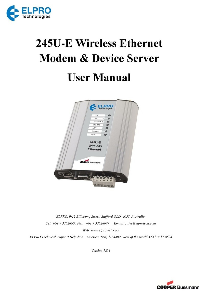
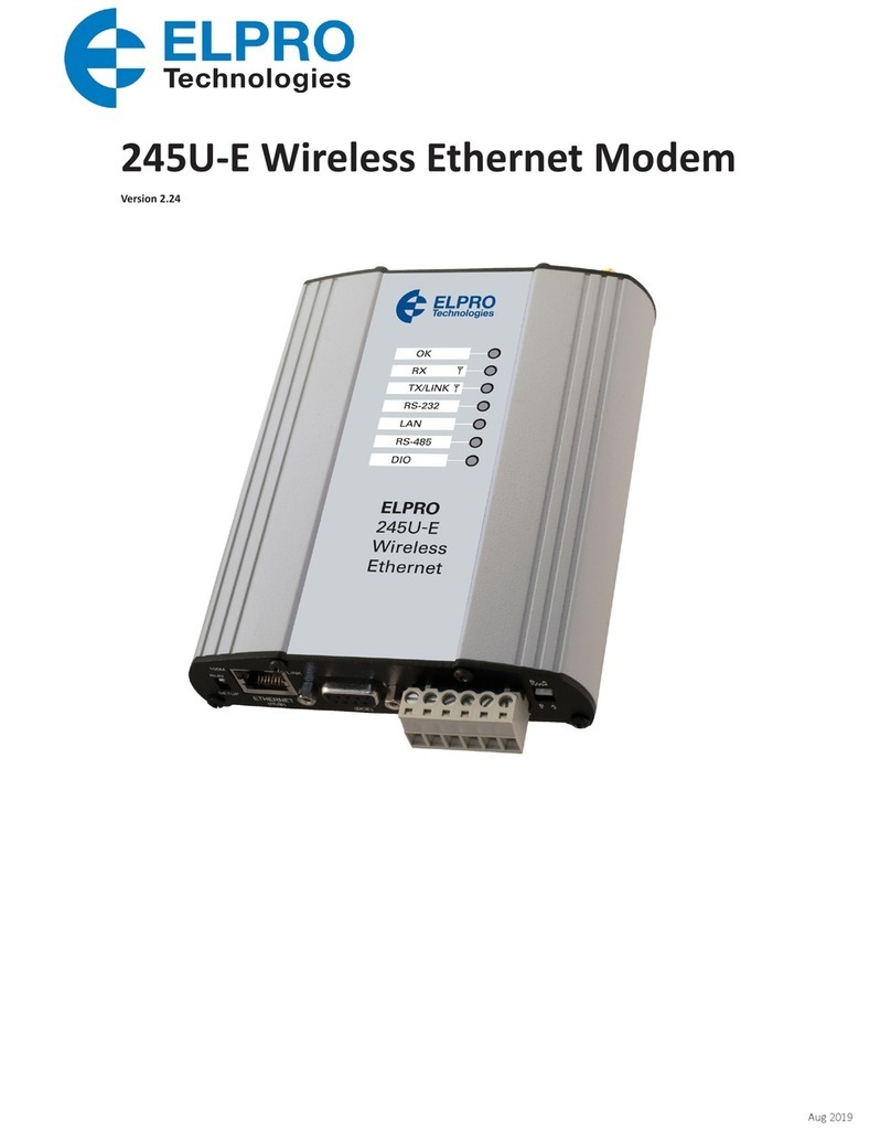
Elpro Technologies 245U-E User manual

Elpro Technologies

Elpro Technologies 245U-E User manual

Elpro Technologies 905U-D User manual

Elpro Technologies

Elpro Technologies 905U-D User manual

Elpro Technologies 245U-E-G User manual

Elpro Technologies

Elpro Technologies 245U-E-G User manual

Elpro Technologies 615M-1 User manual

Elpro Technologies

Elpro Technologies 615M-1 User manual

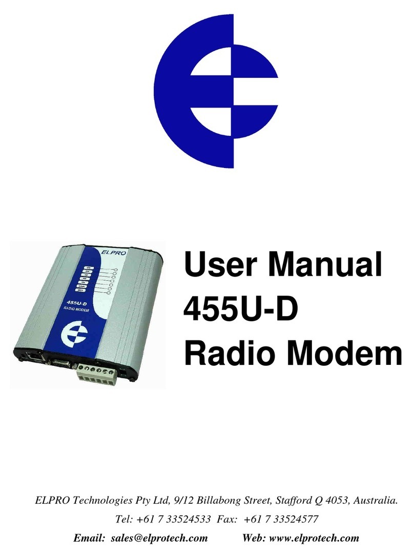
Elpro Technologies 455U-D User manual

Elpro Technologies

Elpro Technologies 455U-D User manual

Popular Modem manuals by other brands

SMC Networks EZ Connect SMC7003USB V.2 user guide

SMC Networks

SMC Networks EZ Connect SMC7003USB V.2 user guide

Paradyne COMSPHERE 3825Plus Safety notes

Paradyne

Paradyne COMSPHERE 3825Plus Safety notes

ADF Web HD67302-B2 Series user manual

ADF Web

ADF Web HD67302-B2 Series user manual

axing EoC 2-01 Premium Line quick start

axing

axing EoC 2-01 Premium Line quick start

Maestro Executive 96M Technical reference manual

Maestro

Maestro Executive 96M Technical reference manual

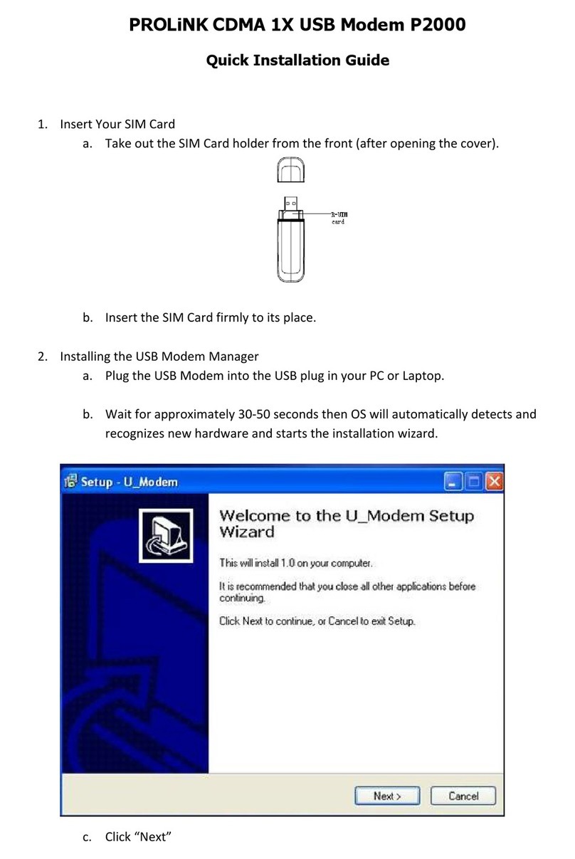
PROLiNK P2000 Quick installation guide

PROLiNK

PROLiNK P2000 Quick installation guide

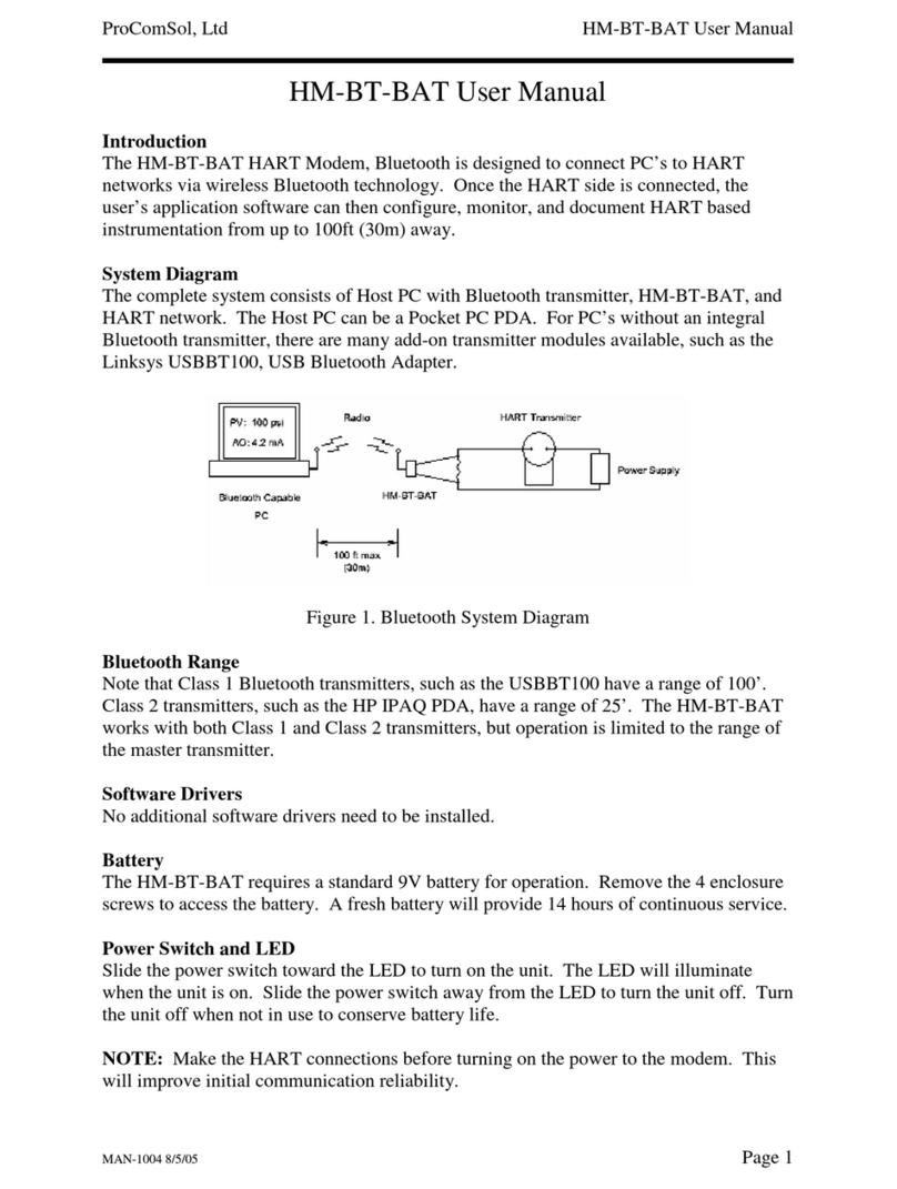
ProComSol HART HM-BT-BAT user manual

ProComSol

ProComSol HART HM-BT-BAT user manual

Motorola SB6100 Specifications

Motorola

Motorola SB6100 Specifications

AVM Fritz!Box Fon WLAN 7270 Installation, configuration and operation

AVM

AVM Fritz!Box Fon WLAN 7270 Installation, configuration and operation

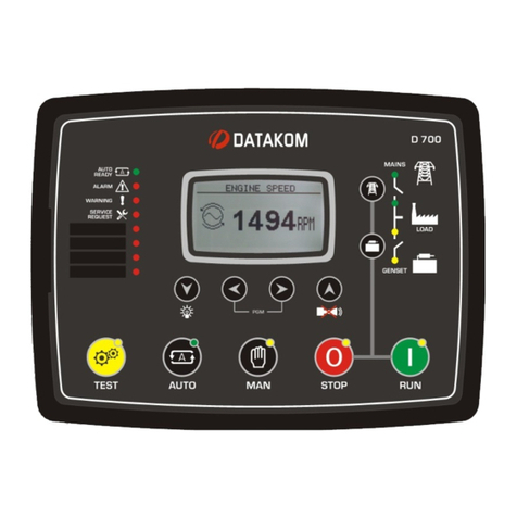
Datakom D-700 Configuration guide

Datakom

Datakom D-700 Configuration guide

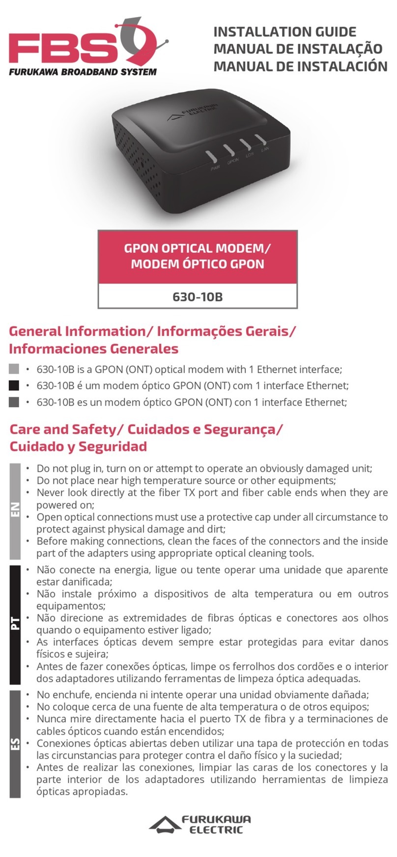
FBS 630-10B installation guide

FBS

FBS 630-10B installation guide

Huawei EchoLife HG556a Installation guide and user's manual

Huawei

Huawei EchoLife HG556a Installation guide and user's manual

Huawei E397U-53 quick start guide

Huawei

Huawei E397U-53 quick start guide

Devolo ADSL Fun LAN Technical specifications

Devolo

Devolo ADSL Fun LAN Technical specifications

Flarion PAD-1000 user guide

Flarion

Flarion PAD-1000 user guide

FALCOM SAMBA3G-E user manual

FALCOM

FALCOM SAMBA3G-E user manual

Garnet GAN-1021 install guide

Garnet

Garnet GAN-1021 install guide

DIGIWEB Fritz!Box 4040 quick start guide

DIGIWEB

DIGIWEB Fritz!Box 4040 quick start guide

manuals.online logo
manuals.online logoBrands
  • About & Mission
  • Contact us
  • Privacy Policy
  • Terms and Conditions

Copyright 2025 Manuals.Online. All Rights Reserved.