Elprotronic FlashPro-CC User manual

FlashPro-CC Flash Programmer
for the CC series devices - Chipcon product from TI
Remote Control Programming User’s Guide
PM024A02 Rev.2
December-17-2007
Elprotronic Inc.

2
Elprotronic Inc.
16 Crossroads Drive
Richmond Hill,
Ontario, L4E-5C9
CANADA
Web site: www.elprotronic.com
E-mail: [email protected]
Fax: 905-780-2414
Voice: 905-780-5789
Copyright © Elprotronic Inc. All rights reserved.
Disclaimer:
No part of this document may be reproduced without the prior written consent of Elprotronic Inc.
The information in this document is subject to change without notice and does not represent a
commitment on any part of Elprotronic Inc. While the information contained herein is assumed to
be accurate, Elprotronic Inc. assumes no responsibility for any errors or omissions.
In no event shall Elprotronic Inc, its employees or authors of this document be liable for special,
direct, indirect, or consequential damage, losses, costs, charges, claims, demands, claims for lost
profits, fees, or expenses of any nature or kind.
The software described in this document is furnished under a licence and may only be used or copied
in accordance with the terms of such a licence.
Disclaimer of warranties: You agree that Elprotronic Inc. has made no express warranties to You
regarding the software, hardware, firmware and related documentation. The software, hardware,
firmware and related documentation being provided to You “AS IS” without warranty or support
of any kind. Elprotronic Inc. disclaims all warranties with regard to the software, express or implied,
including, without limitation, any implied warranties of fitness for a particular purpose,
merchantability, merchantable quality or noninfringement of third-party rights.
Limit of liability: In no event will Elprotronic Inc. be liable to you for any loss of use, interruption
of business, or any direct, indirect, special incidental or consequential damages of any kind
(including lost profits) regardless of the form of action whether in contract, tort (including
negligence), strict product liability or otherwise, even if Elprotronic Inc. has been advised of the
possibility of such damages.

3
END USER LICENSE AGREEMENT
PLEASE READ THIS DOCUMENT CAREFULLY BEFORE USING THE SOFTWARE AND
THE ASSOCIATED HARDWARE. ELPROTRONIC INC. AND/OR ITS SUBSIDIARIES
(“ELPROTRONIC”) IS WILLING TO LICENSE THE SOFTWARE TO YOU AS AN
INDIVIDUAL, THE COMPANY, OR LEGAL ENTITY THAT WILL BE USING THE
SOFTWARE (REFERENCED BELOW AS “YOU” OR “YOUR”) ONLY ON THE CONDITION
THAT YOU AGREE TO ALL TERMS OF THIS LICENSE AGREEMENT. THIS IS A LEGAL
AND ENFORCABLE CONTRACT BETWEEN YOU AND ELPROTRONIC. BY OPENING THIS
PACKAGE, BREAKING THE SEAL, CLICKING “I AGREE” BUTTON OR OTHERWISE
INDICATING ASSENT ELECTRONICALLY, OR LOADING THE SOFTWARE YOU AGREE
TO THE TERMS AND CONDITIONS OF THIS AGREEMENT. IF YOU DO NOT AGREE TO
THESE TERMS AND CONDITIONS, CLICK ON THE “I DO NOT AGREE” BUTTON OR
OTHERWISE INDICATE REFUSAL, MAKE NO FURTHER USE OF THE FULL PRODUCT
AND RETURN IT WITH THE PROOF OF PURCHASE TO THE DEALER FROM WHOM IT
WAS ACQUIRED WITHIN THIRTY (30) DAYS OF PURCHASE AND YOUR MONEY WILL
BE REFUNDED.
1. License.
The software, firmware and related documentation (collectively the “Product”) is the property of
Elprotronic or its licensors and is protected by copyright law. While Elprotronic continues to own
the Product, You will have certain rights to use the Product after Your acceptance of this license.
This license governs any releases, revisions, or enhancements to the Product that Elprotronic may
furnish to You. Your rights and obligations with respect to the use of this Product are as follows:
YOU MAY:
A. use this Product on many computers;
B. make one copy of the software for archival purposes, or copy the software onto the hard disk
of Your computer and retain the original for archival purposes;
C. use the software on a network
YOU MAY NOT:
A. sublicense, reverse engineer, decompile, disassemble, modify, translate, make any attempt
to discover the Source Code of the Product; or create derivative works from the Product;
B. redistribute, in whole or in part, any part of the software component of this Product;

4
C. use this software with a programming adapter (hardware) that is not a product of
Elprotronic Inc.
2. Copyright
All rights, title, and copyrights in and to the Product and any copies of the Product are owned by
Elprotronic. The Product is protected by copyright laws and international treaty provisions.
Therefore, you must treat the Product like any other copyrighted material.
3. Limitation of liability.
In no event shall Elprotronic be liable to you for any loss of use, interruption of business, or any
direct, indirect, special, incidental or consequential damages of any kind (including lost profits)
regardless of the form of action whether in contract, tort (including negligence), strict product
liability or otherwise, even if Elprotronic has been advised of the possibility of such damages.
4. DISCLAIMER OF WARRANTIES.
You agree that Elprotronic has made no express warranties to You regarding the software, hardware,
firmware and related documentation. The software, hardware, firmware and related documentation
being provided to You “AS IS” without warranty or support of any kind. Elprotronic disclaims all
warranties with regard to the software and hardware, express or implied, including, without
limitation, any implied warranties of fitness for a particular purpose, merchantability, merchantable
quality or noninfringement of third-party rights.

5
NOTE: This equipment has been tested and found to comply with the limits for a Class B digital devices,
pursuant to Part 15 of the FCC Rules. These limits are designed to provide reasonable protection against harmful
interference in a residential installation. This equipment generates, uses, and can radiate radio frequency energy
and, if not installed and used in accordance with the instruction manual, may cause harmful interference to
radio communications. However, there is no guarantee that interference will not occur in a particular
installation. If this equipment does cause harmful interference to radio or television reception, which can be
determined by turning the equipment off and on, the user is encouraged to try to correct the interference by one
of more of the following measures:
* Reorient or relocate the receiving antenna
* Increase the separation between the equipment and receiver
* Connect the equipment into an outlet on a circuit different from that to which the receiver is connected
* Consult the dealer or an experienced radio/TV technician for help.
Warning: Changes or modifications not expressly approved by Elprotronic Inc. could void the user’s authority
to operate the equipment.
This device complies with Part 15 of the FCC Rules.
Operation is subject to the following two conditions:
(1) this device may not cause harmful interference and
(2) this device must accept any interference received,
including interference that may cause undesired
operation.
This Class B digital apparatus meets all requirements of the Canadian
Interference-Causing Equipment Regulations.
Cet appereil numerique de la classe B respecte toutes les exigences du
Reglement sur le material brouilleur du Canada.

6
Table of Contents
1. Introduction ............................................................. 9
2.Demoprogram .......................................................... 16
3.GettingStarted .......................................................... 23
3.1 Example with single FPA API DLL . . . . . . . . . . . . . . . . . . . . . . . . . . . . . . . . . . 23
3.2 Example with Multi-FPA API DLL . . . . . . . . . . . . . . . . . . . . . . . . . . . . . . . . . . . 24
4.ListoftheDLLinstructions................................................ 27
4.1Multi-FPAinstructions ............................................ 28
F_Trace_ON.................................................. 28
F_Trace_OFF ................................................. 28
F_OpenInstances .............................................. 28
F_CloseInstances .............................................. 29
F_OpenInstancesAndFPAs, F_OpenInstances_AndFPAs . . . . . . . . . . . . . . 29
F_API_DLL_Directory ......................................... 33
F_Set_FPA_index ............................................. 34
F_Get_FPA_index ............................................. 35
F_Disable_FPA_index.......................................... 35
F_Enable_FPA_index .......................................... 35
F_LastStatus.................................................. 36
F_Multi_DLLTypeVer.......................................... 36
F_Get_FPA_SN ............................................... 37
4.2Genericinstructions ............................................... 38
F_Check_FPA_access .......................................... 38
F_DLLTypeVer ............................................... 40
F_Initialization................................................ 40
F_Close_All .................................................. 41
F_GetSetup .................................................. 42
F_ConfigSetup ................................................ 42
F_SetConfig .................................................. 45
F_GetConfig ................................................. 50
F_DispSetup.................................................. 51

7
F_ReportMessage, F_Report_Message . . . . . . . . . . . . . . . . . . . . . . . . . . . . 51
F_GetReportMessageChar ....................................... 53
F_ReadCodeFile, F_Read_CodeFile . . . . . . . . . . . . . . . . . . . . . . . . . . . . . . 54
F_Get_CodeCS ............................................... 55
F_ConfigFileLoad, F_Config_FileLoad . . . . . . . . . . . . . . . . . . . . . . . . . . . . 56
F_Clr_Code_Buffer ............................................ 57
F_Put_Byte_to_Code_Buffer..................................... 58
F_Get_Byte_from_Code_Buffer . . . . . . . . . . . . . . . . . . . . . . . . . . . . . . . . . . 58
F_Put_IEEEAddr64_to_Buffer . . . . . . . . . . . . . . . . . . . . . . . . . . . . . . . . . . . 59
F_Put_IEEEAddr_Byte_to_Buffer . . . . . . . . . . . . . . . . . . . . . . . . . . . . . . . . 59
F_Get_IEEEAddr64_from_Buffer . . . . . . . . . . . . . . . . . . . . . . . . . . . . . . . . . 60
F_Get_IEEEAddr_Byte_from_Buffer . . . . . . . . . . . . . . . . . . . . . . . . . . . . . . 60
F_Power_Target............................................... 61
F_Reset_Target ............................................... 61
F_Get_Targets_Vcc ............................................ 62
4.3Encapsulatedinstructions........................................... 63
F_AutoProgram ............................................... 63
F_Verify_Lock_Bit ............................................ 64
F_Memory_Erase.............................................. 65
F_Memory_Blank_Check ....................................... 66
F_Memory_Write.............................................. 66
F_Memory_Verify ............................................. 66
F_Memory_Read .............................................. 67
F_Write_IEEE_Address......................................... 68
F_Read_IEEE_Address ......................................... 68
F_Write_Lock_Bits ............................................ 69
4.4Sequentialinstructions ............................................. 70
F_Open_Target_Device ......................................... 71
F_Close_Target_Device......................................... 71
F_Segment_Erase.............................................. 72
F_Sectors_Blank_Check ........................................ 73
F_Write_Byte_to_XRAM ....................................... 73
F_Read_Byte_from_XRAM ..................................... 74
F_Write_Byte_to_direct_RAM . . . . . . . . . . . . . . . . . . . . . . . . . . . . . . . . . . . 75
F_Read_Byte_from_direct_RAM . . . . . . . . . . . . . . . . . . . . . . . . . . . . . . . . . 75
F_Copy_Buffer_to_Flash........................................ 76
F_Copy_Flash_to_Buffer........................................ 76
F_Copy_Buffer_to_XRAM ...................................... 77

8
F_Copy_XRAM_to_Buffer ...................................... 78
F_Copy_Buffer_to_direct_RAM . . . . . . . . . . . . . . . . . . . . . . . . . . . . . . . . . . 79
F_Copy_direct_RAM_to_Buffer . . . . . . . . . . . . . . . . . . . . . . . . . . . . . . . . . . 80
F_Put_Byte_to_Buffer .......................................... 80
F_Get_Byte_from_Buffer ....................................... 81
F_Set_PC_and_RUN ........................................... 81
F_Get_MCU_Data............................................. 82
Appendix A ............................................................... 84
FlashPro-CC Command Line interpreter . . . . . . . . . . . . . . . . . . . . . . . . . . . . . . . . . . 84
9
1. Introduction
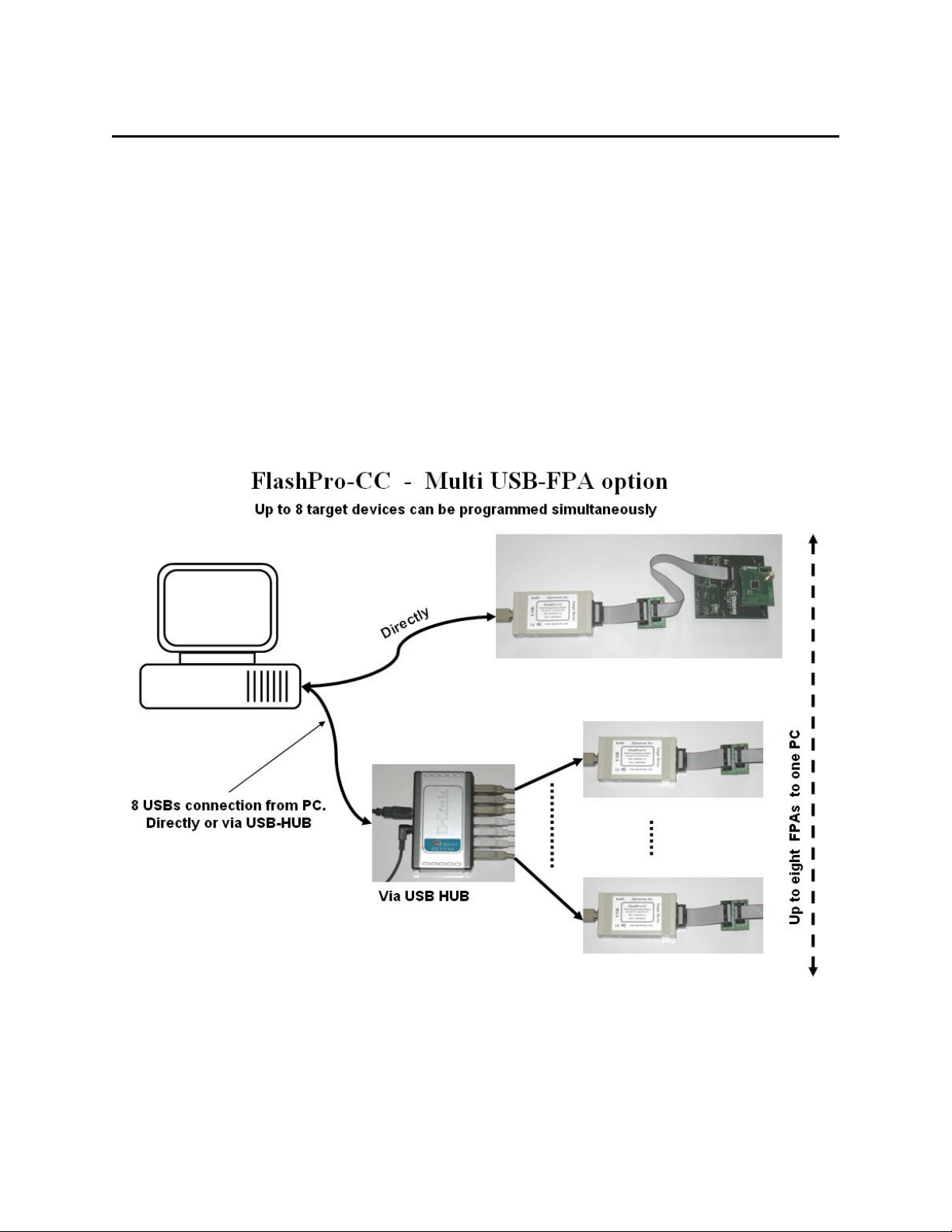
FlashPro-CC Flash Programmer (USB ) can be remotely controlled from other
software applications (Visual C++, Visual Basic etc.) via a DLL library. The Multi-FPA - allows
to remotely control simultaneously up to eight Flash Programming Adapters (FPAs)
significantly reducing programming speed in production.
Figure 1.1 shows the connections between PC and up to eight programming adapters. The
FPAs can be connected to PC USB ports directly or via USB-HUB. Direct connection to the PC
is faster but if the PC does not have required number of USB ports, then USB-HUB can be used.
The USB-HUB should be fast, otherwise speed degradation can be noticed. When the USB hub
is used, then the D-Link’s Model No: DUB-H7, P/N BDUBH7..A2 USB 2.0 HUB is
recommended.
Figure 1.1

10
Remote Control Programming User’s Guide PM024A02 Rev.2 11
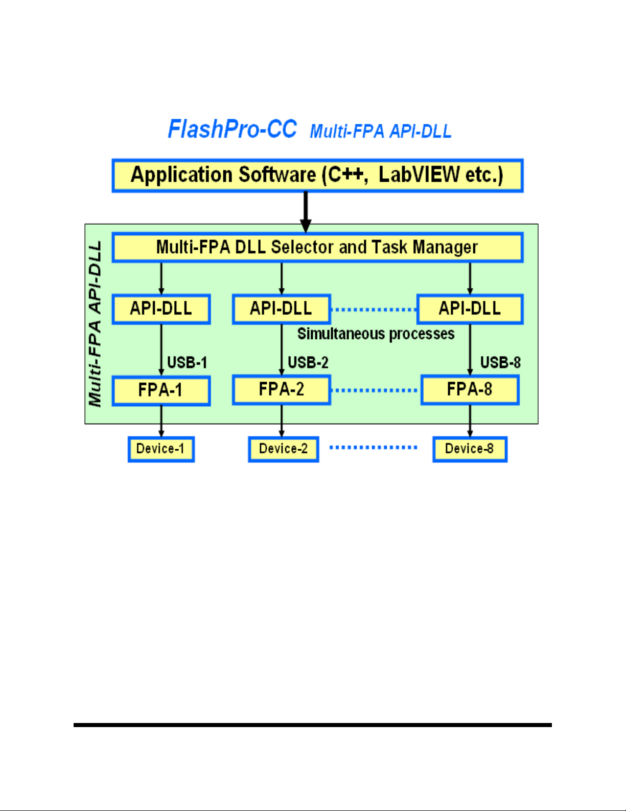
Block diagram of the Multi-FPA application DLL is presented on the Figure 1.2.
To support the Multi-FPA API-DLL feature, the software package contains nine dll files
- the Multi-FPA API-DLL selector
- eight standard single FPAs API-DLLs
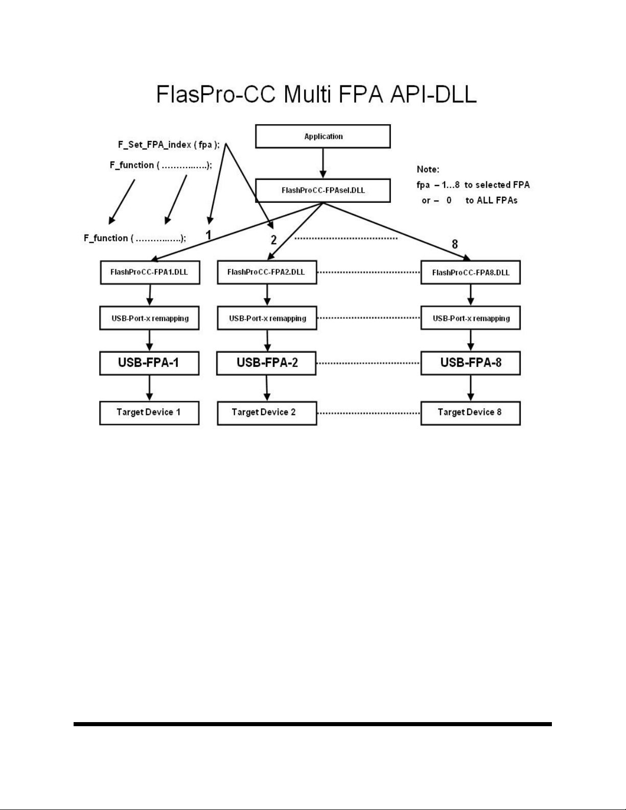
Figure 1.3 shows the logical connections between dll files.
Figure 1.2
Remote Control Programming User’s Guide PM024A02 Rev.2 12
The main FlashProCC-FPAsel.dll (Multi-FPA selector) allows to transfer API-DLL
functions coming from an application software to desired single application dll (FlashProCC-
FPA1.dll to FlashProCC-FPA8.dll).
Note: Software package contains one FlashProCC-FPA1.DLL. Files FlashProCC-
FPA2.DLL to FlashProCC-FPA8.DLL will be copied automatically if required.
The FlashProCC-FPAsel.dll is transparent for all API-DLL functions implemented in the
single API-DLLs functions. Desired destination FPA can be selected using the selector function
added to the Multi-FPA selector (FlashProCC-FPAsel.dll).
F_Set_FPA_index( fpa );
where the
Figure 1.3

Remote Control Programming User’s Guide PM024A02 Rev.2 13
fpa = 1 to 8 when the only one desired FPA required to be selected
or
fpa = 0 when ALL active FPAs should be selected.
The selected FPA index modified by the F_Set_FPA_index( fpa ) instruction can be
modified at any time. By default, the FPA index is 1 and if only one FPA is used then fpa index
does not need to be initialized or modified. When the fpa index 1 to 8 is used, then the result is
coming back to application software from the single API-DLL via transparent Multi-FPA
selector. When the fpa index is 0 (ALL-FPAs) and results are the same from all FPAs, then the
same result is passing back to application software. If results are not the same, then the Multi-
FPA selector DLL is returning value -1 (minus 1) and all recently received results can be read
individually using function
F_LastStatus( fpa )
Most of the implemented functions allows to use the determined fpa index 1 to 8 or 0
(ALL-FPAs). When functions return specific value, like read data etc, then only determined FPA
index can be used ( fpa index from 1 to 8). When the fpa index is 0 (ALL-FPAs) then almost all
functions are executed simultaneously. Less critical functions are executed sequentially from
FPA-1 up to FPA-8 but that process can not be seen from the application software.
When the inactive fpa index is selected, then return value from the selected function is -2
(minus 2). When all fpa has been selected (fpa index = 0) then only active FPAs will be serviced.
For example if only one FPA is active and fpa index=0, then only one FPA will be used. It is
save to prepare the universal application software that allows to remote control up to eight FPAs
and on the startup activate only desired number of FPAs.
It should be noticed, that all single API-DLLs (FlashProCC-FPA1.dll to FlashProCC-
FPA8.dll) used with the Multi-FPA DLL (FlashProCC-FPAsel.dll) are fully independent to each
other. From that point of view it is not required that transferred data to one FPA should be the
same as the transferred data to the others FPAs. For example code data downloaded to FPA-1 can
be different that the code data downloaded to the FPA-2, FPA-3 etc. But even in this case the
programming process can be done simultaneously. In this case the desired code should be read
from the code file and saved in the API-DLL-1, next code file data should be saved in the API-
DLL-2 etc. When it is done, then the F_AutoProgram can be executed simultaneously with
selected all active FPAs. All FPAs will be serviced by his own API-DLL and data packages
saved in these dlls.

Remote Control Programming User’s Guide PM024A02 Rev.2 14
The FlashPro-CC Flash Programmer software package contains all required files to
remotely control programmer from a software application. When software package is installed
then by default the DLL file, library file and header file are located in:
C:\Program Files\Elprotronic\CCxx\USB FlashPro-CC\API-DLL
FlashProCC-FPAsel.dll - Multi-FPA selection / task manager API- DLL
FlashProCC-FPA1.dll - Single api-DLL for the UAB-FPA
FlashProCC-Dll.h - header file for C++
FlashProCC-Dos-Dll.h - header file for C++ (Borland) or DOS
FlashProCC-FPAsel.lib - lib file for C++
FlashProCC-FPAsel-BC.lib - lib file for C++ (Borland)
config.ini - default configuration file for the FPAs
FPAs-setup.ini - FPAs- vs USB ports configuration file
The FlashProCC-FPAsel.dll contains two groups of the same functions used in C++
application and Visual Basic (or similar) applications All procedure names used in Visual Basic
are starting from VB_xxxx, when the procedure names used in C++ are starting from F_xxxx.
All functions starting from F_xxxx using the _Cdecl declarations used in C++ . Function names
starting from VB_xxxx has the _stdcall calling declaration required in Visual Basic.
Reminding files listed above are required in run time - to initialize the flash programming
adapter (config.ini) and USB setup (FPAs-setup.ini).
When the C++ application is created, then following files should be copied to the source
application directory:
FlashProCC-Dll.h - header file for C++
FlashProCC-FPAsel.lib - lib file for C++ (Microscoft Visual C++)
or
FlashProCC-Dos-Dll.h - header file for C++
FlashProCC-FPAsel-BC.lib - lib file for C++ (Borland C++)
and to the release/debug application directory
FlashProCC-FPAsel.dll - Multi-FPA selection / task manager DLL
FlashProCC-FPA1.dll - API-DLL for the USB-FPA
config.ini - default configuration file for the FPAs

Remote Control Programming User’s Guide PM024A02 Rev.2 15
FPAs-setup.ini - FPAs- vs USB ports configuration file
Executable application software package in C++ or when application in Visual Basic is created,
then following files should be copied to the source or executable application directory:
FlashProCC-FPAsel.dll
FlashProCC-FPA1.dll
config.ini
FPAs-setup.ini
All these files ‘as is’ should be copied to destination location, where an application software
using the DLL library.
The config.ini file has default setup information. This file can be modified and taken directly
form the FlashPro-CC Flash Programmer application software. To create required config.ini file
the standard FlashPro-CC Flash programmer software should be open and required setup
(memory option, communication speed etc) should be created. When this is done, programming
software should be closed and the config.ini file with the latest saved configuration copied to
destination location. Note, that the configuration setup can be modified using DLL library
function.
Software package has a demo software written under Visual C++.net. All files and source
code are located in:
C:\Program Files\Elprotronic\CCxx\USB FlashPro-CC\API-DLL-Demo\Cpp

Remote Control Programming User’s Guide PM024A02 Rev.2 16
2. Demo program
The demo program is a small GUI program with a lot of buttons allowing to separately
call functions using DLL library package software. Source code and all related project files are
located in the following directory:
C:\Program Files\Elprotronic\CCxx\USB FlashPro-CC\API-DLL-Demo\Cpp
Program can be activated by selecting the FlashProCC-DLL-DemoCpp.exe located in the \release
subdirectory. This demo program can also be activated from the windows menu:
Start->Program->Elprotronic-Flash Programmer->(CCxx) USB FlashPro-CC->FlashProCC-DLL-Demo-
Cpp

Remote Control Programming User’s Guide PM024A02 Rev.2 17
When the demo program is activated, then the following dialogue screen is displayed (see figure
2.1). At the beginning the USB-FPA’s configuration file should be created, that contains list off
all FPAs used in the application. Using the Notepad editor the default FPA configuration file
‘FPAs-setup.ini’ should be opened by pressing the “Open FPAs-setup.ini” button in the
dialogue screen.
Take a serial numbers from the FPAs labels and write it on the desired FPAs locations FPA-1 up
to FPA-8. If for example two FPAs will be used with SN 20070031 and 20070032 then the
contents of the FPA’s configuration file will be as follows:
;===================================================================
; USB-FPA configuration setup *
; Elprotronic Inc. *
;-------------------------------------------------------------------
; up to eight FPA can be specified and connected via USB to PC *
Figure 2.1 Demo program dialogue screen using DLLs.

Remote Control Programming User’s Guide PM024A02 Rev.2 18
; syntax: *
; FPA-x Serial Number *
; where FPA-x can be FPA-1, FPA-2, FPA-3 .... up to FPA-8 *
; Serial number - get serial number from the desires FPA's label *
; Minimum one FPA's must be specified *
; FPA-x order - any *
; *
; e.g (without semicolon - comment) *
; *
;FPA-1 20050116 *
;FPA-3 20050199 *
;FPA-5 20050198 *
;===================================================================
FPA-1 20070031
FPA-2 20070032
Note, that only lines without comments (without semicolon on the front ) are used by
software. All lines with comment are ignored. The FPA’s serial numbers and FPA’s indexes can
be listed in any order and with gap like FPA-1, FPA-5 etc. without FPA-2, 3 etc. Minimum one
valid FPA with correct SN must be specified. Up to eight FPAs can be declared. When the FPA’s
configuration file is created then file should be saved using name starting from FPA and with
extention ini e.g FPAs-setup.ini.
Connect all required FPA’s to USB connectors and run the FlashProCC-
DLL-Demo-Cpp.exe demo software. First the DLL instances should be opened and all
connected FPA’s should be assigned to desired FPA’s indexes. It is recommended to press the
button ‘FPA assigment’ located inside the frame named ‘From File (recommended)’. When this
button is pressed, then the DLL function named
F_OpenInstancesAndFPAs( FileName );
is called. The list of defined FPA’s serial numbers are taken from the FPAs configuration file and
assigned all FPAs to desired FPA indexes (1 to 8). Number of instances to be opened is
calculated automatically, one per available and valid FPA. On described example with two FPAs
in the ‘FPAs selector’ will display two valid FPAs with list of used FPAs’ serial numbers. All,
others FPA-x fields will be disabled. In this example only two DLL instances becomes opened.
Valid FPA indexes becomes 1,3 and ALL.
Note: When one or more FPA adapters are connected to PC and the “FPAs-setup.ini”
does not contain valid FPA serial numbers, then the first detected FPA (and only one)
will be activated.

Remote Control Programming User’s Guide PM024A02 Rev.2 19
Other method (old method - not recommended) that allows to open required number of
instances uses ‘2. Open Instances’ button in ‘Default’ frame. First the number of the instances
should be defined in the ‘Total no of FPAs’ location. When the ‘2. Open Instances’ button is
pressed, then the DLL function named
F_OpenInstances( no );
called where ‘no’ - number of instances to be opened.. When the dll instances are opened, then it
is possible to check the access to the FPA connected to PC via USB ports. Pressing button ‘3.
FPA list’ ( function F_Check_FPA_access(index); called in loop for index = 1,2,3..8 ) allows
to check the access to these adapters. On the end the button ‘4. FPA assignment’ ( function
F_Check_FPA_access(index); with desired ‘fpa’ and USB indexes) allows to assign desired
FPA adapter to ‘fpa’ index. All these steps can be done automatically when the function
F_OpenInstancesAndFPAs( FileName ) described above is used (used button ‘FPA
assigment’ located inside the frame named ‘From File (recommended) ).
When the FPA(s)s has been assigned then all adapters should be activated by pressing the
‘1. Initialization’ button. This initialization calls the DLL function F_Initialization and
communication between programming adapter and PC is established. Report message is
displayed in the report window ( uses the F_ReportMessage function). By default the config.ini
file is empty and to make a required programmer setup the setup file should be downloaded to
programmer. It can be done by pressing the button ‘ 2.Setup File’, (executing
F_ConfigFileLoad DLL function). Setup file can be prepared first using standard FlashPro-CC
programming software with GUI. Also desired code file can be downloaded by pressing the
button ‘3. Open Code’ (executing F_ReadCodeFile DLL function).
There are seven buttons located on the right side of demo dialogue screen. Each of them
calls one encapsulated function from the following list - F_AutoProgram, F_Memory_Erase,
F_Memory_Blank_Check, F_Memory_Write, F_Memory_Verify and F_Memory_Read
When any of these button is pressed, then a function, exactly in the same way how it is
done in the standard FlashPro-CC Flash Programming software (GUI) is executed. Also buttons
Power ON/OFF, RESET has the same action as related buttons in standard programmer. Refer
to the FlashPro-CC Flash Flash Programmer for the CC series devices - User’s Manual for
details of these functions.
In the central part on dialogue screen there are buttons that can call the sequential DLL
functions.
Button Open Target - F_Open_Target_Device();

Remote Control Programming User’s Guide PM024A02 Rev.2 20
Button Erase Segment - F_Segment_Erase(....);
Button Blank Check Segm. - F_Sectors_Blank_Check(....);
Button Write Flash Block - F_Copy_Buffer_to_Flash(....);
Button Read Flash Block - F_Copy_Flash_to_Buffer(....)
Button Write XRAM Block - F_Copy_Buffer_to_XRAM(....);
Button Read XRAM Block - F_Copy_XRAM_to_Buffer(....);
Button Write direct RAM - F_Copy_Buffer_to_direct_RAM(....);
Button Read direct RAM - F_Copy_direct_RAM_to_Buffer(....);
Button Set PC and Run - F_Set_PC_and_RUN(....);
Button Close Target - F_Close_Target_Device();
When a sequential function is called then Open Target (calling F_Open_Target_Device
DLL function) must be pressed first. After that any button calling a sequential function can be
pressed - in any order and as many times as required. On the end of sequential communication
the button Close Traget (calling F_Close_Target_Device DLL function) should be pressed.
In the presented demo software all sequential functions have very small task to perform to
demonstrate how to use the DLL functions. See source code of the DLL-Demo program in the
software package in the ..\Demo-DLL subdirectory for details.
Erase Segment: Erase segment at location 0x1000 (segment size 1 or 2k )
Blank Check Segm. Segment blank check Erase at location 0x1000 to 0x107F
Write Flash Block Write 16 bytes to the flash memory at location 0x1020 to 0x102f using
function
F_Copy_Buffer_to_Flash( 0x1020, 16);
Following data are written no targets:
0x1020 -> 10 11 12 13 14 15 16 17 18 19 1A 1B 1C 1D 1E 1F
Read Flash Block Read 64 bytes from target device starting from the flash memory address
at 0x1000. On the report screen only 16 bytes from each target devices
taken from addresses 0x1020 to 0x102F are displayed.
Write XRAM Block Write 16 bytes to XRAM at location 0xF000 to 0xF00F using function
F_Copy_Buffer_to_XRAM( 0xF000, 16);
Following data are written no targets:
30 31 32 33 34 35 36 37 38 39 3A 3B 3C 3D 3E 3F
Table of contents
Other Elprotronic Motherboard manuals


