7
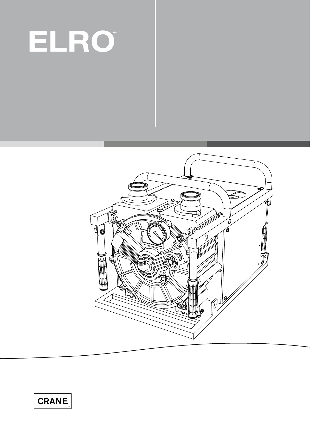
ELRO®Peristaltic Pumps Series M300 / T300
Fig. 1: Exemplary installation for peristaltic pumps
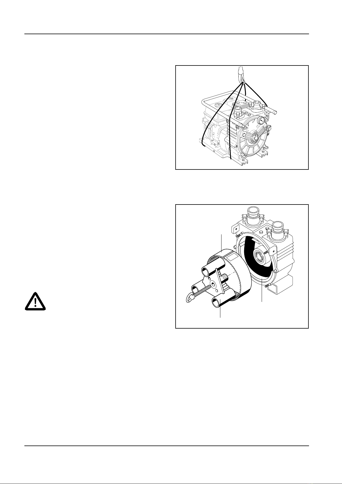
1.0 Introduction
ELRO®Peristaltic pumps M300/T300 are dimen-
sioned as pumps in accordance with chapter 1,
article 1, section (2), paragraph (j), point (ii) of the
pressure equipment directive and are therefore
no pressure equipment as dened by the EC
pressure equipment directive 2014/68/EEC.
The following instructions refer only to the peri-
staltic pumps M300 and T300.
Since the pumps will be used in
combination with other assem-
blies, such as combustion engines
and electric motors, you must also
strictly observe and comply with
the operating and maintenance
instructions for these components
as well as the corresponding
notes on safe and reliable opera-
tion.
These instructions contain information for in-
stallation, operation and maintenance of peri-
staltic pumps ELRO M300 and T300.
You should therefore thoroughly read these
instructions before use and always follow the
information contained therein.
All personnel involved in activities
on pump or equipment must have
read this manual, especially the
chapter ”Safety” before starting
work. This is too late once work
has started. This applies especial-
ly for persons who work on the
pump only occasionally, e.g. for
maintenance and cleaning work.
Each pump is subject to stringent inspections
and function tests before leaving the factory.
You should always bear in mind that a correct
function, a long lifetime and optimal opera-
tional reliability of the pump mainly depend
on
ncorrect installation
ncorrect commissioning
nand proper maintenance.
Enquiries concerning service, spare parts or
repairs should be addressed to the manufac-
turer or an authorized dealer.
Always provide the following information:
n Pump type
nSerial number of pump
This information is stamped on the identica-
tion plate on the base of the pump.
When returning pumps or pump parts to
the manufacturer or an authorized dealer
for repair or overhaul, the delivery must be
accompanied by a certicate stating that the
pump is free of product or other aggressive
or hazardous substances (see page 37).
1.1 Warranty
The correct function of each ELRO peristaltic
pump is checked in the factory before ship-
ment. The manufacturer assumes warranty
for his product as specied in the eective
terms of sales and delivery. Faults resulting
from the non-compliance with the aforemen-
tioned regulations and notes can only be
rectied at the cost of the customer.
Caution!
Caution!