Elsema Gigalink GLR2702 User manual

ELSEMA
2-Channel 27MHz GIGALINK™ Receiver with relay outputs, GLR2702
- 1 -
GLR2702
2-Channel 27MHz Gigalink™ Receiver
Features
• Wide supply connection – 11.0 to 28.0 Volts AC/DC
• Highly sensitive receiver input stage. When used with GLT27….
series transmitters and an ANT27L antenna, an operating range of 350
metres (980 ft) is possible.
• Two relay outputs. Both outputs can be operated simultaneously.
• Crystal controlled for high stability and performance.
• Dual Conversion to reduce interference.
• Uses micro-controller technology that can be re-programmed to suit
unique applications.
• Momentary, latching and security latching output modes is user
selectable.
• Power ON LED indicator.
• Test buttons for relay.
Applications
• Automatic gates, security, timer controlled outputs and simple on/off functions etc
Description
The GIGALINK™ is an advanced Remote Control technology available in the world today. GIGALINK™ is
an invention that has revolutionised the entire Remote Control technology including Elsema's earlier version of
FMT- … and FMR- … series.
The GLR2702 series state-of-the-art invention brings a new dimension in the world of Remote Control
technology in domestic, commercial and industrial applications.
The innovative microcontroller technology replaces the traditional dip switch coding which eliminates any
possible code grabbing. Special features such as over four billion code combinations, ability to program any
number of transmitters to any of the receiver outputs, three user selectable modes, dual conversion superhet and
operational over a wide voltage range all adds up to the most advanced and secure Remote Control available.
Four billion codes
The user can easily change the code on all the channels. Momentary joining the two CC pins on the receiver
board sets all channels to one random code. One of 4,294,967,296 possibilities is selected.
Code Programming
For code programming, please refer to the separate programming instructions.

ELSEMA
2-Channel 27MHz GIGALINK™ Receiver with relay outputs, GLR2702
- 2 -
When programming is completed and the GIGALINK cable is removed from the multi channel receiver-coding
socket, the 2-way dip switch is used to select different output modes. This is described below.
Output Modes
Relay output on the receiver can function in either momentary or latching mode. By default the mode is set to
momentary. Modes selectable from the 2-way dipswitch. Dipswitch 1 corresponds to relay channel 1 and
dipswitch 2 corresponds to relay channel 2.
Factory Default = Momentary
Momentary - Output is active for as long as the transmitter button is pressed.
This is a standard mode on most automatic gates or garage door openers.
Latching - Output remains active until next press of the transmitter button.
Similar to switching "on" and "off" a light.
Security
Latching
-
Output remains active until power to the receiver is removed. Similar to security alarms
and fire alarms. To activate the security latching mode, a link needs to be soldered into the
hole marked as latching.
Customised Software
Custom output modes can be programmed to do special functions. Call Elsema for more details.
Products in the Range
GLR2701
1-Channel
GLR2701240
1-Channel, 240V
GLR2702
2-Channel
GLR2702240
2-Channel, 240V
GLR2703
3-Channel Receiver
GLR2704
4-Channel
Receiver
GLR2708
8-Channel
GLR2708R
8-Channel with
Relay Output
GLR2701SS
GLR2702SS
1,2 -Channel, Open
Collector Output
GLR2701SST
GLR2702SST
1,2 -Channel, Open
Collector Output

ELSEMA
2-Channel 27MHz GIGALINK™ Receiver with relay outputs, GLR2702
- 3 -
Technical Data
Supply Voltage
11.0 to 28 VDC and 10.0 to 28 VAC.
Can use Elsema AC power pack (PP12 or PP24).
Supply lines should be less than 3 metres long to comply with radio frequency
authorities.
Current Consumption
14mA standby at 12 VDC Supply
63mA if relay “ON” at 12 VDC Supply
Receiving Frequency
27.195MHz
Operating Temperature
Range
-5 to 50°C
Sensitivity
1uV (for output to activate)
Decoding System
Microcontroller based 96-bit word
Code Combinations
4,294,967,296
Outputs
Two change over relay outputs, rated at 8 Amps/240 Volts
Connections
Supply, Antenna & Outputs: Screw type terminal block
Antenna
50 ohms, 27MHz CB-Antenna or approximately 1m long & 1mm thick piece
of wire
Dimensions
96 x 70 x 20mm
Mounting Hole Size
3.97mm or 5/32"
Weight
83g
Microcontroller
Can be re-programmed to suit your customised needs
Useable Transmitters
All Elsema Type 27MHz GLT-... series
Useable Operating Range
Up to 350m with proper 50 ohms, 27MHz CB-Antenna. Up to 200m with 1m
long antenna wire. Antenna wire should be extended and away from metal.
Ranges assume line-of-sight operation.

ELSEMA
2-Channel 27MHz GIGALINK™ Receiver with relay outputs, GLR2702
- 4 -
Block Diagram

ELSEMA
2-Channel 27MHz GIGALINK™ Receiver with relay outputs, GLR2702
- 5 -
Sh terminal is used for antenna's using coaxial cables. The shield (braid) on the coaxial cable should be
connected to the Sh terminal while the core of the coaxial cable is connected to the A terminal.

ELSEMA
2-Channel 27MHz GIGALINK™ Receiver with relay outputs, GLR2702
- 6 -
GLR2702 12/24 VDC Application

ELSEMA
2-Channel 27MHz GIGALINK™ Receiver with relay outputs, GLR2702
- 7 -
GLR2702 110/240 VAC Application

ELSEMA
2-Channel 27MHz GIGALINK™ Receiver with relay outputs, GLR2702
- 8 -
REGULATORY COMPLIANCE STATEMENTS
American Users
This device complies with Part 15 of the FCC Rules. Operation is subject to the following two conditions:
(1) This device may not cause harmful interference and
(2) This device must accept any interference received, including interference that may cause undesired
operation.
FCC Notice
This device has been tested and found to comply with the limits for a Class B digital device, pursuant to Part 15
of the FCC Rules. These limits are designed to provide reasonable protection against harmful interference in a
residential installation. This device generates, uses, and can radiate radio frequency energy and, if installed and
used in accordance with the instruction, may cause harmful interference to radio communications. However,
there is no guarantee that interference will not occur in a particular installation. If this device does cause
harmful interference to radio or television reception, the user is encouraged to try to correct the interference by
one or more of the following measures:
•Reorient or relocate the receiving antenna.
•Increase the separation between the computer and receiver.
•Connect the computer into an outlet on a circuit different from that to which the receiver is connected.
•Consult the dealer or an experienced radio/TV technician for help.
Caution: Any changes or modifications not expressly approved by the grantee of this device could void the
user’s authority to operate the equipment.
Canadian Users
This Class [B] digital apparatus meets all requirements of the Canadian Interference-Causing Equipment
Regulations.
Cet appareil numérique de la classe [B] respecte toutes les exigences du Règlement sur le matériel brouilleur du
Canada.
Australian and New Zealand Users
This device has been tested and found to comply with the limits for a Class [B] digital device, pursuant to the
Australian/New Zealand Electromagnetic compatibility (EMC) standard AS/NZS 61000.6.3 set out by the
Spectrum Management Agency.
Table of contents
Other Elsema Receiver manuals
Elsema
Elsema GIGALINK GLR2702240 Series User manual
Elsema
Elsema Gigalink GLR43308 Installation manual
Elsema
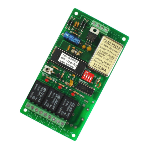
Elsema GLR2703 User manual

Elsema
Elsema G4000 User manual
Elsema
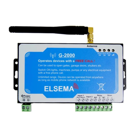
Elsema G-2000 User manual

Elsema
Elsema Gigalink GLR2708 User manual
Elsema
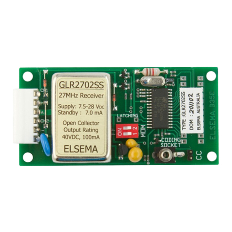
Elsema GLR2701SS User manual
Elsema
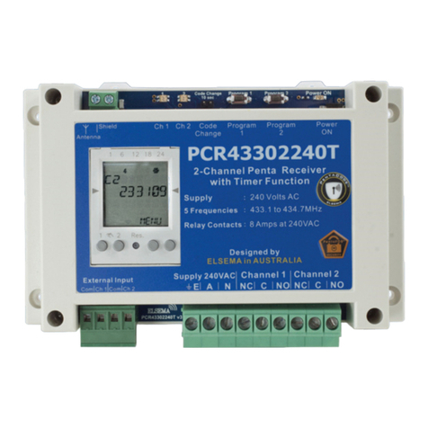
Elsema PentaTimer PCR43302240T User manual
Elsema
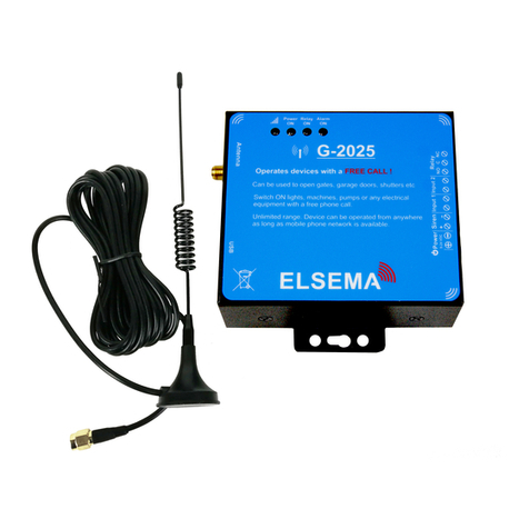
Elsema G-2025 User manual
