manuals.online logo
Brands
  1. Home
  2. •
  3. Brands
  4. •
  5. elsner elektronik
  6. •
  7. Switch
  8. •
  9. elsner elektronik Nunio KNX M-T User manual

elsner elektronik Nunio KNX M-T User manual

Nunio KNX M-T push button 1
Nunio KNX M-T push button • Version: 04.02.2021 • Technical changes and errors excepted. • Elsner Elektronik GmbH • Sohlengrund 16 • 75395 Ostelsheim • Germany • www.elsner-elektronik.de • Technical Service: +49 (0) 7033 / 30945-250
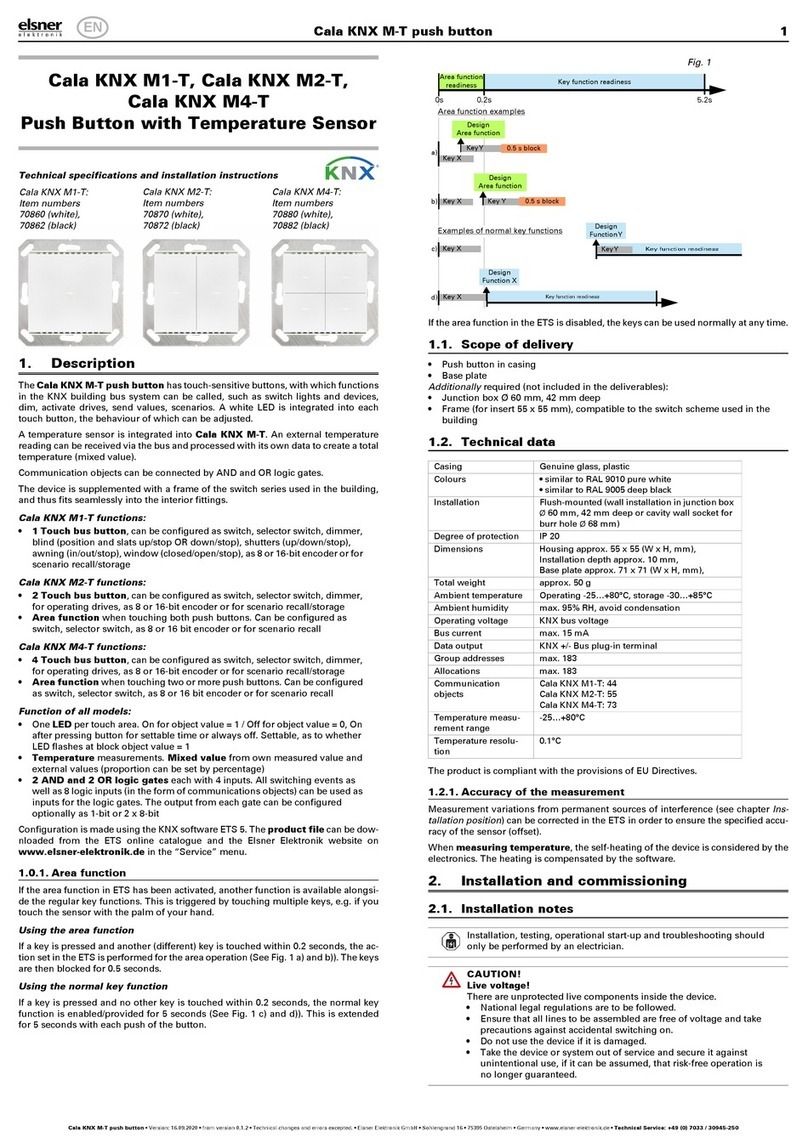
Nunio KNX M-T
Push Button
Technical specifications and installation instructions
Item number 71280
1. Description
The Nunio KNX M-T push button is a touch switch that be universally used for
the KNX building system. It has a monochrome touch display, on which buttons
can be displayed in various arrangements. The functions of the buttons are defined
individually. As a result, the sensor is extremely flexible with regard to changing
requirements (change of tenant in residential or commercial properties, hotel
rooms, etc.).
A temperature sensor is integrated into Nunio KNX M-T push button. An exter-
nal temperature reading can be received via the bus and processed with its own
data to create a total temperature (mixed value).
Nunio KNX M-T has a PI controller for heating and cooling. A temperature control
display can also be represented on the screen. The target temperature, mode and,
if applicable, the fan speed can be set there.
Communication objects can be linked via AND and OR logic gates.
The switch-sized device has an integrated glass frame, which is backlit by the
screen's lighting. It installed in a switch box.
Functions:
•Display screen with one, two, three or four touch buttons. Icon and text
selectable for each button. Each button can be configured as a switch,
changer, drive (shutter, blind, awning or window with short/long difference),
window, dimmer, 8 or 16-bit encoder or to call/save scenes
•Display lighting with adjustable basic brightness (standby) and operating
brightness. With active operating lighting, the outsides of the frame are
also illuminated.
•Area functionif touched with the hand or when wiping. Can be configured
as switch, selector switch, as 8 or 16 bit encoder or for scenario recall
•Menu for temperature control with +/- buttons (warmer, cooler), target
value display, mode selection button and fan speed setting
• Display lighting adjustable, including switched off in standby mode
•Temperature measurements. Mixed value from own measured value and
external values (proportion can be set by percentage), output of minimum
and maximum values
•PI-controller for heating (one or two-level) and cooling (one or two-
level) according to temperature. Control according to separate setpoints or
basic setpoint temperature. With fan-coil control
•2 AND and 2 OR logic gates each with 4 inputs. Switching events as well
as 8 logic inputs (in the form of communications objects) can be used as
inputs for the logic gates. The output from each gate can be configured
optionally as 1-bit or 2 x 8-bit
1.1. Scope of delivery
• Sensor with integrated frame
• Base plate
1.1.1. Accessories required
• Device socket according to DIN 49073
1.2. Technical data
The product conforms to the conditions of the EU Directives.
1.2.1. Accuracy of the measurement
Measurement variations from permanent sources of interference (see chapter Ins-
tallation position) can be corrected in the ETS in order to ensure the specified ac-
curacy of the sensor (offset).
When measuring temperature, the self-heating of the device is considered by
the electronics. The heating is compensated by the software.
Configuration is made using the KNX software ETS 5. The product file can be
downloaded from the ETS online catalogue and the Elsner Elektronik website on
www.elsner-elektronik.de in the “Service” menu.
1.2.2. Device structure
2. Safety and operating instructions
2.1. Installation notes
Installation, testing, operational start-up and troubleshooting should
only be performed by an electrician.
CAUTION!
Live voltage!
There are unprotected live components inside the device.
• National legal regulations are to be followed.
• Ensure that all lines to be assembled are free of voltage and take
precautions against accidental switching on.
• Do not use the device if it is damaged.
• Take the device or system out of service and secure it against
unintentional use, if it can be assumed, that risk-free operation is
no longer guaranteed.
The device is only to be used for the intended purpose described in this manual.
Any improper modification or failure to follow the operating instructions voids any
and all warranty and guarantee claims.
After unpacking the device, check it immediately for possible mechanical damage.
If it has been damaged in transport, inform the supplier immediately.
The device may only be used as a fixed-site installation; that means only when as-
sembled and after conclusion of all installation and operational start-up tasks and
only in the surroundings designated for it.
Elsner Elektronik is not liable for any changes in norms and standards which may
occur after publication of these operating instructions.
3. Installation
3.1. Installation location and preparation
The Nunio KNX M-T push button is installed on a socket. For correct tempera-
ture recording, a wind-tight socket must be used. The casing of the device must not
be opened.
May be installed and operated in dry interior rooms only.
Avoid condensation.
When selecting an installation location, please ensure that the measurement re-
sults are affected as little as possible by external influences. Possible sources of in-
terference include:
• Direct sunlight
• Drafts from windows and doors
• Draft from ducts which lead from other rooms or from the outside to the
junction box in which the sensor is mounted
• Warming or cooling of the building structure on which the sensor is
mounted, e.g. due to sunlight, heating or cold water pipes
• Connection lines and ducts which lead from warmer or colder areas to the
sensor
Measurement variations from permanent sources of interference can be corrected
in the ETS in order to ensure the specified accuracy of the sensor (offset).
3.2. Connection
For installation and wiring at the KNX connection, the
provisions and standards applicable to SELV circuits must be
complied with!
The socket, in which the Nunio KNX M-T push button is installed, must not con-
tain cabling with 230 V.
First install the windproof socket with feed line. Seal the inlet tubes as well, in order
to prevent draughts.
Then screw the baseplate to the box.
Connect the KNX databus +/- to the KNX connection terminal (black-red). A brai-
ded sleeve must be used here, which isolates the cables and shields the bus line.
Insert the device firmly onto the metal frame using the catches so that the device
and the housing are fixed together.
4. Commissioning
After the bus voltage has been applied, the unit will enter an initialisation phase
lasting approx. 5 seconds. During this period, no information can be received or
transmitted via the bus.
4.1. Address the device on the bus
The physical address is assigned by the ETS. The device has a sensor and a control
LED (fig. 1, No. 4+5).
The equipment is delivered with the bus address 15.15.255. Another address can
be programmed using the ETS.
5. Views and device operation
5.1. Buttons
One, two, three or more buttons can be represented on the display. The definition
is entered into ETS. The functions and symbols are allocated here, and two text va-
riants, each with 12 letters/numbers are entered.
General:
Casing Genuine glass, plastic
Colours similar to RAL 9010 pure white
Assembly on device socket according to DIN 49073
Size 85 mm × 85 mm (W × H),
Installation via socket approx. 10.5 mm,
Total depth approx. 31 mm,
Support frame approx. 71 mm × 71 mm (W × H)
Total weight approx. 140 g
Display resolution 160 × 160 px
Ambient temperature 0…+55°C
Ambient humidity 5...80% RH, non-condensing
Storage temperature -30…+80°C
Overvoltage category III
Degree of contamina-
tion
2
KNX bus:
KNX medium TP1-256
Configuration mode S-Mode
Group addresses max. 254
Assignments max. 254
Communication
objects
106
Nominal voltage KNX 30 V SELV
Power consumption
KNX
maximum 25 mA
Connection KNX plug terminals
Duration after bus vol-
tage restoration until
data is received
approx. 5 seconds
Sensor:
Temperature measu-
rement range
0…+55°C
Temperature resolu-
tion
0.1°C
Fig. 1: Back
1Catches
2 KNX terminal BUS +/-
3 Ventilation slot temperature
measurement
4 Programming LED (recessed)
5 Programming LED (recessed)
for teaching the device
6 Base frame
4
5
6
1
2
3
Fig. 2: Cross-section representati-
on
Installation depth
20.5 mm
Installation
10.5 mm
Fig. 3: 1 button
Touch area
1Areaforsymbol
2 Individual text
1
2
EN
Nunio KNX M-T push button 2
Nunio KNX M-T push button • Version: 04.02.2021 • Technical changes and errors excepted. • Elsner Elektronik GmbH • Sohlengrund 16 • 75395 Ostelsheim • Germany • www.elsner-elektronik.de • Technical Service: +49 (0) 7033 / 30945-250
5.2. Symbol overview
The following symbols can be selected in the device application (ETS):
5.3. Area function
If the area function in ETS has been activated, another function is available along-
side the regular key functions. This is triggered by touching or wiping over an area,
e.g. if you touch the sensor with the palm of your hand.
Using the area function
The display area of the sensor is divided into four virtual areas, which correspond
to the buttons for the setting “4 buttons”. The virtual areas are independent of the
buttons shown. They remain the same, irrespective of whether one, two, three or
four buttons are displayed.
If one of the four areas is touched and another (different) virtual real is touched wit-
hin 0.2 seconds a key is pressed and another (different) key is touched within one
second, the action set in the ETS is performed for the area operation (Siehe a) and
b)). The touch function is then blocked for 0.5 seconds.
Using the normal key function
If one of the key areas displayed is pressed and no other virtual area is touched wit-
hin 0.2 seconds, the normal key function is enabled for 5 seconds (Siehe c) and d)).
This that if the 0.2 seconds have passed, different buttons or even the same button
can be pressed multiple times and the normal button function is executed. With
each new touch of a button, the readiness for the normal button function is exten-
ded by 5 seconds.
If the area function in the ETS is disabled, the keys can be used normally at any ti-
me.
5.4. Temperature controller menu
If the temperature controller of the Nunio KNX M-T is used, a temperature cont-
roller menu can be represented. The temperature controller menu must be activa-
ted in the ETS.
An area °C is then shown at the top right of the button display. Tap it to open the
temperature controller menu.
Change target temperature
The target value for the active heating or cooling mode is displayed (Fig. 9b, No.
4) and can be changed with +/- (Fig. 9b, No. 5+6).
In the device application (temperature controller, ETS), however, it can be
specified that the target cannot be changed for each mode. If the manual mo-
dification of the nominal value is blocked in one mode, the symbol "Manual
blocked" is briefly shown when an attempt is made to modify the value.
The increment and the possible setting range are also specified in the application's
temperature controller. Whether the manually changed values are retained after a
mode change (e.g. Eco mode over night), or if the stored values are reapplied, is
also defined here.
Change mode
Tap the Mode symbol (Fig. 9b, No. 7) in order to display the possible operating
modes one after another. This causes a frame around the symbol to flash. To con-
firm the selection and activate the displayed mode, remain on the symbol for a litt-
le longer. The frame briefly flashes faster and then disappears. The mode is activa-
ted.
The manual selection possibility can be restricted in the device application (tempe-
rature controller, ETS).
A small additional symbol indicates whether heating or cooling is in progress (ma-
nipulated variable not equal to zero).
Touch the symbol “Comfort extension” in order to change from Eco mode brief-
ly into Comfort mode. This allows the user to maintain the nominal comfort value
for a longer time, e.g. when having guests.
The duration of this comfort extension period is set in the ETS. The remaining time
is shown next to the symbol. After the comfort extension period is terminated, the
system returns to Eco mode.
The comfort extension option may also be blocked in the ETS (symbol does not ap-
pear for selection).
Change fan speed
If Control of a fan (fan coil) is selected in the ETC, touching the fan symbol (Fig.
9b, No. 8) switches between
AX = Automatic with current level
M0 = Manually switched off
M1 = Manual level 1
M2 = Manual level 2
M3 = Manual level 3
When switching through the levels, a frame around the fan symbol flashes. To con-
firm the selection and activate the displayed mode, remain on the symbol for a litt-
le longer. The frame briefly flashes faster and then disappears. The mode is activa-
ted.
Blocking and jumping back
The button function of the temperature controller display can be pre-
vented because of an active operating mode with priority 1 (e.g. buil-
ding protection during window ventilation). This is displayed by the sym-
bol “Manual change blocked”.
In the application one can specify that the display automatically jumps back to
“Sensor” if the display in the temperature controller menu has not been touched
for the entered time.
6. Maintenance
Ventilation slits must not be dirty of covered. If required, wipe the device with a
soft, dry cloth.
7. Disposal
After use, the device must be disposed of or recycled in accordance with the legal
regulations. Do not dispose of it with the household waste!
Fig. 4: 2 buttons horizontal
Touch areas
1 Areas for symbols
2 Individual text
1
1
2
2
Fig. 5: 2 buttons vertical
Touch areas
1 Areas for symbols
2 Individual text
11
22
Fig. 6: 3 buttons
Touch areas
1 Areas for symbols
2 Individual text
1
1
1
2
2
2
Fig. 7: 4 buttons
Touch areas
1 Areas for symbols
2 Individual text
1
2
1
1 1
2
2 2
None 0 1 Scene
Socket Light Suspended
lights
Standard lamp
Table lamp Wall lights Ceiling lights Floor
lamp
Blind
closed
Blind
open
Shutters
closed
Shutters
open
Awning
retracted
Awning
extended
Windows
closed
Windows
open
Key function readiness
Fig. 8
V area = virtual area
0s 0.2s 5.2s
V area 3
Key X
Key X
Design
FunctionY
Key function readiness
Readiness
0.5 s block
V area 4
Design
Area function
Key Y
Design
Function X
a)
b)
c)
d)
V area 1
V area 2 0.5 s block
Design
Area function
Area function examples
Examples of normal key functions
Area function
(V area 3)
(V area 2)
(V area 1)
Fig. 9 a
1 To the temperature controller
menu
1 2
5 6
3
4
7 8
Button display Temperature controller menu
Fig. 9 b
2 Return to scanner
3 Temperature controller label-
ling field (free text)
4 Target value display (value of
the active mode)
5 - Lower target value
6 + Increase target value
7 Mode display and selection
8 Fan controls (optional)
Comfort Standby Eco Building pro-
tection
Heating mode Cooling mode
Comfort extension

Other manuals for Nunio KNX M-T

1

This manual suits for next models

1

Other elsner elektronik Switch manuals

elsner elektronik Cala KNX MultiTouch T Series Guide

elsner elektronik

elsner elektronik Cala KNX MultiTouch T Series Guide

elsner elektronik Cala KNX M1-T User manual

elsner elektronik

elsner elektronik Cala KNX M1-T User manual

elsner elektronik 70860 User manual

elsner elektronik

elsner elektronik 70860 User manual

elsner elektronik Corlo Touch KNX WL User manual

elsner elektronik

elsner elektronik Corlo Touch KNX WL User manual

elsner elektronik Cala KNX Multitouch T Light/Sunblind User manual

elsner elektronik

elsner elektronik Cala KNX Multitouch T Light/Sunblind User manual

elsner elektronik P03i/P04i User manual

elsner elektronik

elsner elektronik P03i/P04i User manual

Popular Switch manuals by other brands

TRENDnet TEG-S224TX user guide

TRENDnet

TRENDnet TEG-S224TX user guide

Telebyte CFA-24 Reference manual

Telebyte

Telebyte CFA-24 Reference manual

CYP PUV-2608TX Operation manual

CYP

CYP PUV-2608TX Operation manual

Vivanco FSS 31000W manual

Vivanco

Vivanco FSS 31000W manual

GRASS VALLEY 7620PX datasheet

GRASS VALLEY

GRASS VALLEY 7620PX datasheet

Belkin F5U261 user manual

Belkin

Belkin F5U261 user manual

Dataprobe IP-410 - manual

Dataprobe

Dataprobe IP-410 - manual

Vigitron MaxiiNet Vi32226 Operational manual

Vigitron

Vigitron MaxiiNet Vi32226 Operational manual

D-Link DUB-H7 - Hub - USB Technical specifications

D-Link

D-Link DUB-H7 - Hub - USB Technical specifications

MDT Technologies KNX AKK-0216.03 operating instructions

MDT Technologies

MDT Technologies KNX AKK-0216.03 operating instructions

Cisco uBR-3x10 Hardware  installation and cabling guide

Cisco

Cisco uBR-3x10 Hardware installation and cabling guide

OFFICINE OROBICHE 20 Series instruction manual

OFFICINE OROBICHE

OFFICINE OROBICHE 20 Series instruction manual

Techly IDATA HDMI-22BI2 user manual

Techly

Techly IDATA HDMI-22BI2 user manual

Audio Authority 1821 user manual

Audio Authority

Audio Authority 1821 user manual

Omron A22E-MP manual

Omron

Omron A22E-MP manual

ZyXEL Communications XS1930-12F user guide

ZyXEL Communications

ZyXEL Communications XS1930-12F user guide

Agilent Technologies E1463A User's manual and scpi programming guide

Agilent Technologies

Agilent Technologies E1463A User's manual and scpi programming guide

MS Sedco 216 installation instructions

MS Sedco

MS Sedco 216 installation instructions

manuals.online logo
manuals.online logoBrands
  • About & Mission
  • Contact us
  • Privacy Policy
  • Terms and Conditions

Copyright 2025 Manuals.Online. All Rights Reserved.