Cala KNX M-T push button 1
Cala KNX M-T push button • Version: 07.06.2022 • from version 0.1.4 • Technical changes and errors excepted. • Elsner Elektronik GmbH • Sohlengrund 16 • 75395 Ostelsheim • Germany • www.elsner-elektronik.de • Technical Service: +49 (0) 7033 / 30945-250
EN
Cala KNX M1-T, Cala KNX M2-T,
Cala KNX M4-T
Push Button with Temperature Sensor
Technical specifications and installation instructions
1. Description
The Cala KNX M-T push button has touch-sensitive buttons, with which functions
in the KNX building bus system can be called, such as switch lights and devices,
dim, activate drives, send values, scenarios. A white LED is integrated into each
touch button, the behaviour of which can be adjusted.
A temperature sensor is integrated into Cala KNX M-T. An external temperature
reading can be received via the bus and processed with its own data to create a total
temperature (mixed value).
Communication objects can be connected by AND and OR logic gates.
The device is supplemented with a frame of the switch series used in the building,
and thus fits seamlessly into the interior fittings.
Cala KNX M1-T functions:
•1Touch bus button, can be configured as switch, selector switch, dimmer,
blind (position and slats up/stop OR down/stop), shutters (up/down/stop),
awning (in/out/stop), window (closed/open/stop), as 8 or 16-bit encoder or for
scenario recall/storage
Cala KNX M2-T functions:
•2 Touch bus button, can be configured as switch, selector switch, dimmer,
for operating drives, as 8 or 16-bit encoder or for scenario recall/storage
•Area function when touching both push buttons. Can be configured as
switch, selector switch, as 8 or 16 bit encoder or for scenario recall
Cala KNX M4-T functions:
•4 Touch bus button, can be configured as switch, selector switch, dimmer,
for operating drives, as 8 or 16-bit encoder or for scenario recall/storage
•Area function when touching two or more push buttons. Can be configured
as switch, selector switch, as 8 or 16 bit encoder or for scenario recall
Function of all models:
•OneLED per touch area. On for object value = 1 / Off for object value = 0, On
after pressing button for settable time or always off. Settable, as to whether
LED flashes at block object value = 1
•Temperature measurements. Mixed value from own measured value and
external values (proportion can be set by percentage)
•2 AND and 2 OR logic gates each with 4 inputs. All switching events as
well as 8 logic inputs (in the form of communications objects) can be used as
inputs for the logic gates. The output from each gate can be configured
optionally as 1-bit or 2 x 8-bit
Configuration is made using the KNX software as of ETS 5. The product file can be
downloaded from the ETS online catalogue and the Elsner Elektronik website on
www.elsner-elektronik.de in the “Service” menu. There you will also find the
product manual.
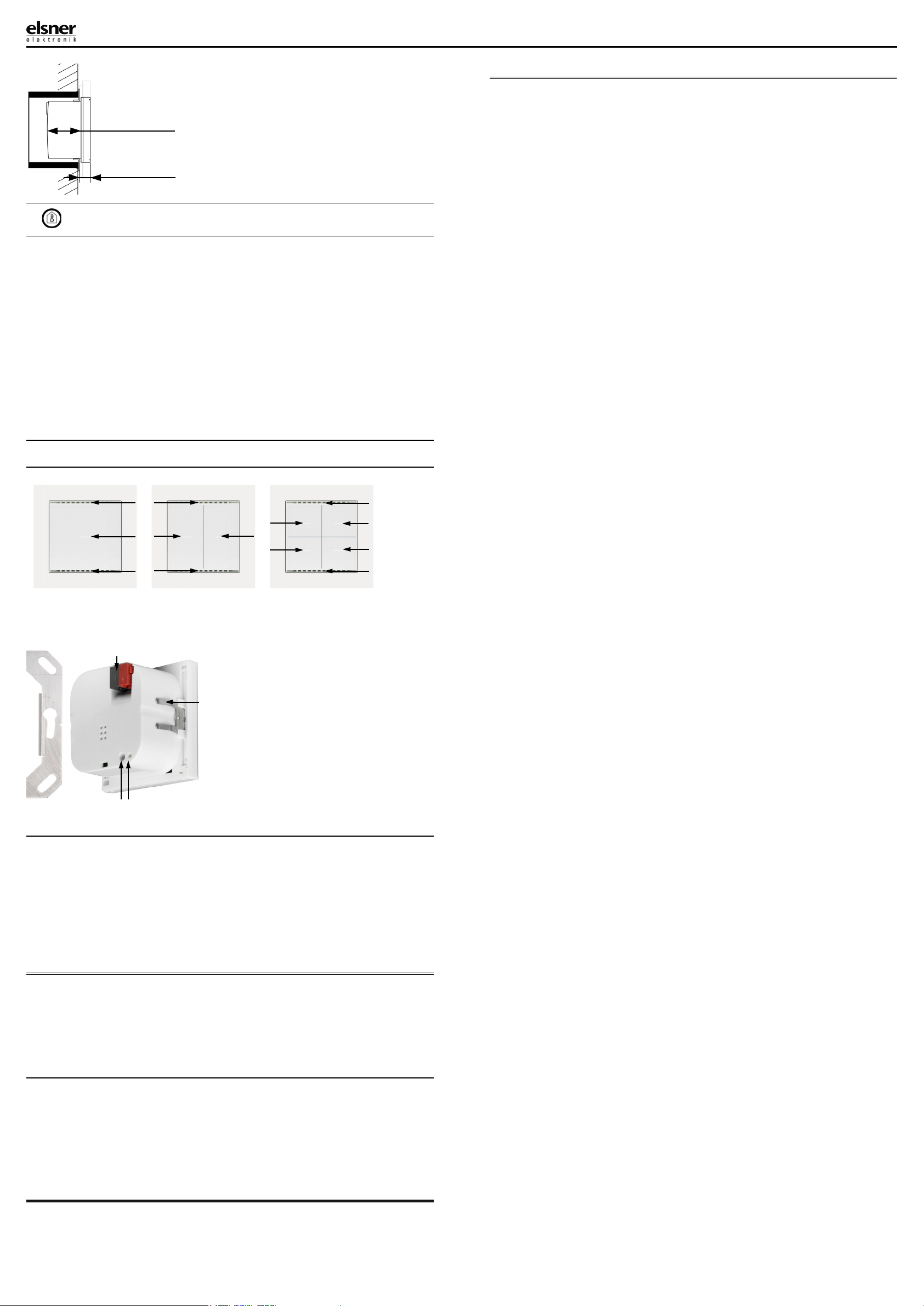
1.0.1. Area function
If the area function in ETS has been activated, another function is available alongsi-
de the regular key functions. This is triggered by touching multiple keys, e.g. if you
touch the sensor with the palm of your hand.
Using the area function
If a key is pressed and another (different) key is touched within 0.2 seconds, the ac-
tion set in the ETS is performed for the area operation (See Fig. 1 a) and b)). The keys
are then blocked for 0.5 seconds.
Using the normal key function
If a key is pressed and no other key is touched within 0.2 seconds, the normal key
function is enabled/provided for 5 seconds (See Fig. 1 c) and d)). This is extended
for 5 seconds with each push of the button.
If the area function in the ETS is disabled, the keys can be used normally at any time.
1.1. Scope of delivery
• Push button in casing
• Base plate
Additionally required (not included in the deliverables):
• Device socket according to DIN EN IEC 60670-1
• Frame (for insert 55 x 55 mm), compatible to the switch scheme used in the
building
1.2. Technical data
The product is compliant with the provisions of EU Directives.
2. Installation and commissioning
Installation, testing, operational start-up and troubleshooting should
only be performed by an authorised electrician.
CAUTION!
Live voltage!
There are unprotected live components inside the device.
• Inspect the device for damage before installation. Only put undamaged
devices into operation.
• Comply with the locally applicable directives, regulations and provisions for
electrical installation.
• Immediately take the device or system out of service and secure it against
unintentional switch-on if risk-free operation is no longer guaranteed.
Use the device exclusively for building automation and observe the operating inst-
ructions. Improper use, modifications to the device or failure to observe the opera-
ting instructions will invalidate any warranty or guarantee claims.
Operate the device only as a fixed-site installation, i.e. only in assembled condition
and after conclusion of all installation and operational start-up tasks, and only in the
surroundings designated for it.
Elsner Elektronik is not liable for any changes in norms and standards which may
occur after publication of these operating instructions.
2.1. Installation location
The Cala KNX M-T push button is designed for wall installation in a connector
socket (Ø 60 mm, 42 mm deep).
Cala KNX M1-T:
Item numbers
70860 (white),
70862 (black)
Cala KNX M2-T:
Item numbers
70870 (white),
70872 (black)
Cala KNX M4-T:
Item numbers
70880 (white),
70882 (black)
Casing Genuine glass, plastic
Colours • similar to RAL 9010 pure white
• similar to RAL 9005 deep black
Installation on device socket according to
DIN EN IEC 60670-1
Degree of protection IP 20
Dimensions Housing approx. 55 x 55 (W x H, mm),
Installation depth approx. 10 mm,
Base plate approx. 71 x 71 (W x H, mm),
Total weight approx. 50 g
Ambient temperature Operating -25…+80°C, storage -30…+85°C
Ambient humidity max. 95% RH, avoid condensation
Operating voltage KNX bus voltage
Bus current max. 15 mA
Data output KNX +/- Bus plug-in terminal
Group addresses max. 183
Allocations max. 183
Communication
objects
Cala KNX M1-T: 44
Cala KNX M2-T: 55
Cala KNX M4-T: 73
Temperature measu-
rement range
-25…+80°C
Temperature resolu-
tion
0.1°C
Key function readiness
Key function readiness
Fig. 1
0s 0.2s 5.2s
Key Y
Key X
Key X
Design
FunctionY
Key function readiness
Area function
Examples of normal key functions
0.5 s block
Key X
Design
Area function
KeyY
Design
Function X
a)
b)
c)
d)
Key X
KeyY 0.5 s block
Design
Area function
Area function examples
readiness